User Manual
Page 3
...1 Introduction 4 1.1 Package Contents 4 1.2 Specifications 5 1.3 Motherboard Layout 7 1.4 ASRock I/OTM 8 2 Installation 9 2.1 Screw Holes 9 2.2 Pre-installation Precautions 9 2.3 CPU Installation 10 2.4 Installation of Heatsink and CPU fan 10 2.5 Installation of Memory Modules (DIMM 11 2.6 Expansion Slots 12 2.7 ..., Boot, and Exit Menus ...... 21 4 Software Support 22 4.1 Installing Operating System 22 4.2 Support CD Information 22 4.2.1 Running Support CD 22 4.2.2 Drivers Menu 22 4.2.3 Utilities Menu 22 4.2.4 ASRock "PC-DIY Live Demo" Program 22 4.2.5 Contact Information...
...1 Introduction 4 1.1 Package Contents 4 1.2 Specifications 5 1.3 Motherboard Layout 7 1.4 ASRock I/OTM 8 2 Installation 9 2.1 Screw Holes 9 2.2 Pre-installation Precautions 9 2.3 CPU Installation 10 2.4 Installation of Heatsink and CPU fan 10 2.5 Installation of Memory Modules (DIMM 11 2.6 Expansion Slots 12 2.7 ..., Boot, and Exit Menus ...... 21 4 Software Support 22 4.1 Installing Operating System 22 4.2 Support CD Information 22 4.2.1 Running Support CD 22 4.2.2 Drivers Menu 22 4.2.3 Utilities Menu 22 4.2.4 ASRock "PC-DIY Live Demo" Program 22 4.2.5 Contact Information...
User Manual
Page 4
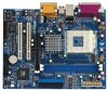
... may find the latest memory and CPU support lists on page 23 offers more advanced BIOS setup information. Chapter 3 and 4 contain basic BIOS setup and support CD information. ASRock website http://www.asrock.com 1.1 Package Contents ASRock K7VM3 motherboard (Micro ATX form factor: 9.6" x 7.5", 24.4 x 19.1 cm) ASRock K7VM3 Quick Installation Guide ASRock AMD-VIA Series Support CD 1 cable for IDE devices...
... may find the latest memory and CPU support lists on page 23 offers more advanced BIOS setup information. Chapter 3 and 4 contain basic BIOS setup and support CD information. ASRock website http://www.asrock.com 1.1 Package Contents ASRock K7VM3 motherboard (Micro ATX form factor: 9.6" x 7.5", 24.4 x 19.1 cm) ASRock K7VM3 Quick Installation Guide ASRock AMD-VIA Series Support CD 1 cable for IDE devices...
User Manual
Page 5
...; 98 SE / ME / 2000 / XP compliant 5 SMBIOS 2.3.1 support; Can connect up events; Supports "Plug and Play"; ACPI 1.1 compliance wake up to protect CPU life (ASRock U-COP)(see CAUTION 3) PS/2: 1 keyboard port / 1 mouse port; 1 RJ 45 port; 4 rear default USB 2.0 ports; 1 VGA port; 1 parallel port: ECP/EPP support; CPU fan tachometer; Audio Jack: Line Out / Line In...
...; 98 SE / ME / 2000 / XP compliant 5 SMBIOS 2.3.1 support; Can connect up events; Supports "Plug and Play"; ACPI 1.1 compliance wake up to protect CPU life (ASRock U-COP)(see CAUTION 3) PS/2: 1 keyboard port / 1 mouse port; 1 RJ 45 port; 4 rear default USB 2.0 ports; 1 VGA port; 1 parallel port: ECP/EPP support; CPU fan tachometer; Audio Jack: Line Out / Line In...
User Manual
Page 10
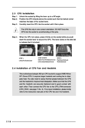
... 7, No. 3). 2.3 CPU Installation Step 1. Step 3. Step 4. You also need to spray thermal grease between the CPU and the heatsink to support AMD Athlon XP / Duron CPU. Then connect the CPU fan to avoid bending of CPU Fan and Heatsink This motherboard adopts 462-pin CPU socket to improve heat dissipation.... DO NOT force the CPU into the socket until ...
... 7, No. 3). 2.3 CPU Installation Step 1. Step 3. Step 4. You also need to spray thermal grease between the CPU and the heatsink to support AMD Athlon XP / Duron CPU. Then connect the CPU fan to avoid bending of CPU Fan and Heatsink This motherboard adopts 462-pin CPU socket to improve heat dissipation.... DO NOT force the CPU into the socket until ...

User Manual
Page 15
... item 13) Clear CMOS CLRCMOS2 solder points (see p.7 item 18) 2-pin jumper Note: CLRCMOS1 and CLRCMOS2 allow you to short the pin on CLRCMOS1 by ASRock. Please turn off the computer and unplug the power cord, then you may not apply to remove the paper clip or the jumper cap after... clearing the CMOS. 15 Please understand that ASRock does not guarantee and support the adjustment of the system or damage the CPU. or you may cause the instability of multiplier. These jumpers setting may either short the solder points on ...
... item 13) Clear CMOS CLRCMOS2 solder points (see p.7 item 18) 2-pin jumper Note: CLRCMOS1 and CLRCMOS2 allow you to short the pin on CLRCMOS1 by ASRock. Please turn off the computer and unplug the power cord, then you may not apply to remove the paper clip or the jumper cap after... clearing the CMOS. 15 Please understand that ASRock does not guarantee and support the adjustment of the system or damage the CPU. or you may cause the instability of multiplier. These jumpers setting may either short the solder points on ...

User Manual
Page 17
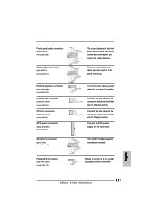
...(9-pin PANEL1) (see p.7 item 17) External speaker connector (4-pin SPEAKER 1) (see p.7 item 15) Chassis fan connector (3-pin CHA_FAN1) (see p.7 item 14) CPU fan connector (3-pin CPU_FAN1) (see p.7 item 3) ATX power connector (20-pin ATXPWR1) (see p.7 item. 16) RRXD1 DDTR#1 DDSR#1 CCTS#1 1 RRI#1 ...RRTS#1 GND TTXD1 DDCD#1 This COM1 header supports a serial port module. 1 PLEDPLED+ PLED+ Please connect a 3-pin power LED cable to this connector. 17 R MIC-POWER MIC PLED+ PLEDPWRBTN# GND 1 ...
...(9-pin PANEL1) (see p.7 item 17) External speaker connector (4-pin SPEAKER 1) (see p.7 item 15) Chassis fan connector (3-pin CHA_FAN1) (see p.7 item 14) CPU fan connector (3-pin CPU_FAN1) (see p.7 item 3) ATX power connector (20-pin ATXPWR1) (see p.7 item. 16) RRXD1 DDTR#1 DDSR#1 CCTS#1 1 RRI#1 ...RRTS#1 GND TTXD1 DDCD#1 This COM1 header supports a serial port module. 1 PLEDPLED+ PLED+ Please connect a 3-pin power LED cable to this connector. 17 R MIC-POWER MIC PLED+ PLEDPWRBTN# GND 1 ...

User Manual
Page 24
...Support: Use this field at the default value unless the installed AGP card's specifications requires other sizes. Chipset Configuration: Advanced AMIBIOS SETUP UTILITY - DRAM CAS# Latency: This is [High]. Configuration options: [Auto],[3.0],[2.5], [2]. The default value is [Auto]. AGP Aperture Size: It refers to increase the CPU... Mode AGP Aperture Size AGP Fast Write Onboard VGA Share Memory PCI Delay Transaction USB Controller USB Device Legacy Support SDRAM CAS# Latency Over Vcore Voltage VCCM Voltage V-Link Speed Auto 128MB Disabled Auto Disabled Enabled Disabled Auto ...
...Support: Use this field at the default value unless the installed AGP card's specifications requires other sizes. Chipset Configuration: Advanced AMIBIOS SETUP UTILITY - DRAM CAS# Latency: This is [High]. Configuration options: [Auto],[3.0],[2.5], [2]. The default value is [Auto]. AGP Aperture Size: It refers to increase the CPU... Mode AGP Aperture Size AGP Fast Write Onboard VGA Share Memory PCI Delay Transaction USB Controller USB Device Legacy Support SDRAM CAS# Latency Over Vcore Voltage VCCM Voltage V-Link Speed Auto 128MB Disabled Auto Disabled Enabled Disabled Auto ...
Quick Installation Guide
Page 4
... the BIOS software might be updated, the content of this manual will be subject to protect CPU life (ASRock U-COP)(see CAUTION 2) AMR slot: 1 slot, supports AMR modem card English 4 ASRock K7VM3 Motherboard IDE2: ATA 133 / Ultra DMA Mode 6; CPU overheat shutdown to change without further notice. Introduction Thank you for AMD AthlonTM / AthlonTM XP/ DuronTM...
... the BIOS software might be updated, the content of this manual will be subject to protect CPU life (ASRock U-COP)(see CAUTION 2) AMR slot: 1 slot, supports AMR modem card English 4 ASRock K7VM3 Motherboard IDE2: ATA 133 / Ultra DMA Mode 6; CPU overheat shutdown to change without further notice. Introduction Thank you for AMD AthlonTM / AthlonTM XP/ DuronTM...
Quick Installation Guide
Page 5
... 2.0 ports upgrade (see CAUTION 4) Microsoft® Windows® 98 SE / ME / 2000 / XP compliant CAUTION! 1. English 5 ASRock K7VM3 Motherboard SMBIOS 2.3.1 support; Supports "Plug and Play"; Audio Jack: Line Out / Line In / Microphone + Game port AMI legal BIOS; CPU frequency stepless control (only for advanced users' reference, see CAUTION 3) PS/2: 1 keyboard port / 1 mouse port; 1 RJ 45...
... 2.0 ports upgrade (see CAUTION 4) Microsoft® Windows® 98 SE / ME / 2000 / XP compliant CAUTION! 1. English 5 ASRock K7VM3 Motherboard SMBIOS 2.3.1 support; Supports "Plug and Play"; Audio Jack: Line Out / Line In / Microphone + Game port AMI legal BIOS; CPU frequency stepless control (only for advanced users' reference, see CAUTION 3) PS/2: 1 keyboard port / 1 mouse port; 1 RJ 45...
Quick Installation Guide
Page 9
...may either short the solder points on CLRCMOS2 for you to the default setup. English 9 ASRock K7VM3 Motherboard or you may use a jumper cap to page 14 of user Manual in CMOS includes...remember to adjust the multiplier of FID jumpers are 2 ways for 3 seconds. The data in the Support CD. There are designed to remove the paper clip or the jumper cap after clearing the CMOS. ...CLRCMOS1 (see p.2 item 13) Clear CMOS CLRCMOS2 solder points (see p.2 item 2) Note: The set of CPU. FID Jumpers (FID0, FID1, FID2, FID3, FID4) (see p.2 item 18) 2-pin jumper Note: CLRCMOS1...
...may either short the solder points on CLRCMOS2 for you to the default setup. English 9 ASRock K7VM3 Motherboard or you may use a jumper cap to page 14 of user Manual in CMOS includes...remember to adjust the multiplier of FID jumpers are 2 ways for 3 seconds. The data in the Support CD. There are designed to remove the paper clip or the jumper cap after clearing the CMOS. ...CLRCMOS1 (see p.2 item 13) Clear CMOS CLRCMOS2 solder points (see p.2 item 2) Note: The set of CPU. FID Jumpers (FID0, FID1, FID2, FID3, FID4) (see p.2 item 18) 2-pin jumper Note: CLRCMOS1...
Quick Installation Guide
Page 11
...matching the black wire to the ground pin. Connect an ATX power supply to this connector. This COM1 header supports a serial port module. English 11 ASRock K7VM3 Motherboard Front panel audio connector (9-pin AUDIO1) (see p.2 item 26) System panel connector (9-pin PANEL1) (see... p.2 item 17) External speaker connector (4-pin SPEAKER1) (see p.2 item 15) Chassis fan connector (3-pin CHA_FAN1) (see p.2 item 14) CPU fan connector (3-pin ...
...matching the black wire to the ground pin. Connect an ATX power supply to this connector. This COM1 header supports a serial port module. English 11 ASRock K7VM3 Motherboard Front panel audio connector (9-pin AUDIO1) (see p.2 item 26) System panel connector (9-pin PANEL1) (see... p.2 item 17) External speaker connector (4-pin SPEAKER1) (see p.2 item 15) Chassis fan connector (3-pin CHA_FAN1) (see p.2 item 14) CPU fan connector (3-pin ...


