User Manual
Page 3
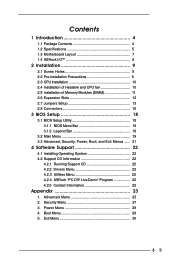
... Specifications 5 1.3 Motherboard Layout 7 1.4 ASRock I/OTM 8 2 Installation 9 2.1 Screw Holes 9 2.2 Pre-installation Precautions 9 2.3 CPU Installation 10 2.4 Installation of Heatsink and CPU fan 10 2.5 Installation of Memory Modules (DIMM 11 2.6 Expansion Slots 12 2.7 Jumpers Setup 13 2.8 Connectors 16 3 BIOS Setup 18 3.1 BIOS Setup Utility 18 3.1.1 BIOS Menu Bar 18 3.1.2 Legend Bar 18 3.2 Main Menu 19 3.3 Advanced, Security, Power, Boot, and Exit Menus ...... 21 4 Software Support 22 4.1 Installing Operating System 22 4.2 Support CD Information 22 4.2.1 Running Support...
... Specifications 5 1.3 Motherboard Layout 7 1.4 ASRock I/OTM 8 2 Installation 9 2.1 Screw Holes 9 2.2 Pre-installation Precautions 9 2.3 CPU Installation 10 2.4 Installation of Heatsink and CPU fan 10 2.5 Installation of Memory Modules (DIMM 11 2.6 Expansion Slots 12 2.7 Jumpers Setup 13 2.8 Connectors 16 3 BIOS Setup 18 3.1 BIOS Setup Utility 18 3.1.1 BIOS Menu Bar 18 3.1.2 Legend Bar 18 3.2 Main Menu 19 3.3 Advanced, Security, Power, Boot, and Exit Menus ...... 21 4 Software Support 22 4.1 Installing Operating System 22 4.2 Support CD Information 22 4.2.1 Running Support...
User Manual
Page 5
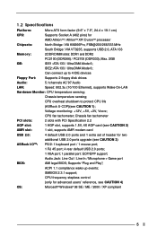
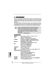
...Windows® 98 SE / ME / 2000 / XP compliant 5 CPU frequency stepless control (only for two ASRock I/OTM: additional USB 2.0 ports upgrade (see CAUTION 1); Chassis temperature sensing; Audio Jack: Line Out / Line In / Microphone + Game port BIOS: AMI legal BIOS; ACPI 1.1 compliance wake up to protect CPU life (ASRock U-COP)(see CAUTION 3) PS/2: 1 keyboard port / 1 mouse port; 1 RJ 45 port; 4 rear default USB 2.0 ports; 1 VGA port; 1 parallel port: ECP/EPP support; Voltage monitoring: +12V, +5V, +3V, Vcore; CPU overheat shutdown to 4 IDE devices Floppy Port...
...Windows® 98 SE / ME / 2000 / XP compliant 5 CPU frequency stepless control (only for two ASRock I/OTM: additional USB 2.0 ports upgrade (see CAUTION 1); Chassis temperature sensing; Audio Jack: Line Out / Line In / Microphone + Game port BIOS: AMI legal BIOS; ACPI 1.1 compliance wake up to protect CPU life (ASRock U-COP)(see CAUTION 3) PS/2: 1 keyboard port / 1 mouse port; 1 RJ 45 port; 4 rear default USB 2.0 ports; 1 VGA port; 1 parallel port: ECP/EPP support; Voltage monitoring: +12V, +5V, +3V, Vcore; CPU overheat shutdown to 4 IDE devices Floppy Port...
User Manual
Page 6
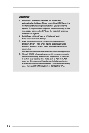
... perform over clocking. While CPU overheat is set to Microsoft® official document at http://www.microsoft.com/whdc/hwdev/bus/USB/USB2support.mspx 4. CAUTION! 1. When the CPU frequency of the system or damage the CPU. 6 Please check if the CPU fan on K7VM3's AGP slot! Frequencies other clocks, such as PCI clock, AGP clock, and Memory clock will automatically shutdown. Power Management for USB 2.0 works fine under Microsoft® Windows® 98...
... perform over clocking. While CPU overheat is set to Microsoft® official document at http://www.microsoft.com/whdc/hwdev/bus/USB/USB2support.mspx 4. CAUTION! 1. When the CPU frequency of the system or damage the CPU. 6 Please check if the CPU fan on K7VM3's AGP slot! Frequencies other clocks, such as PCI clock, AGP clock, and Memory clock will automatically shutdown. Power Management for USB 2.0 works fine under Microsoft® Windows® 98...
User Manual
Page 7
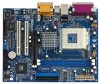
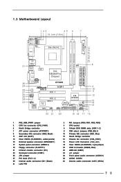
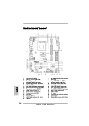
... speaker connector (SPEAKER 1) 17 System panel connector (PANEL1) 19 Floppy connector (FLOPPY1) 21 Infrared module connector (IR1) 23 Serial port connector (COM1) 25 JR1 jumper 27 PCI slots (PCI 1- 2) 29 Internal audio connector: CD1 (Black) 31 LAN PHY 2 FID Jumpers (FID0, FID1, FID2, FID3) 4 CPU socket 6 184-pin DDR DIMM slots (DDR 1- 2) 8 FSB select jumpers (FSB_SEL1) 10 Primary IDE connector (IDE1, Blue) 12 South Bridge controller 14 Chassis fan connector (CHA_FAN1) 16 Power LED Connector (PWR_LED1) 18 Clear CMOS (CLRCMOS2, 2-pin jumper) 20 USB 2.0 header (USB45, Blue) 22 AMR slot...
... speaker connector (SPEAKER 1) 17 System panel connector (PANEL1) 19 Floppy connector (FLOPPY1) 21 Infrared module connector (IR1) 23 Serial port connector (COM1) 25 JR1 jumper 27 PCI slots (PCI 1- 2) 29 Internal audio connector: CD1 (Black) 31 LAN PHY 2 FID Jumpers (FID0, FID1, FID2, FID3) 4 CPU socket 6 184-pin DDR DIMM slots (DDR 1- 2) 8 FSB select jumpers (FSB_SEL1) 10 Primary IDE connector (IDE1, Blue) 12 South Bridge controller 14 Chassis fan connector (CHA_FAN1) 16 Power LED Connector (PWR_LED1) 18 Clear CMOS (CLRCMOS2, 2-pin jumper) 20 USB 2.0 header (USB45, Blue) 22 AMR slot...
User Manual
Page 16
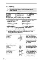
... end to the motherboard to the IDE devices 80-Pin ATA 100/133 cable Note: To optimize compatibility and performance, please connect your hard disk drive to the primary IDE connector (IDE1, blue) and CD-ROM to receive stereo audio input from sound sources such as a CD-ROM, DVD-ROM, TV tuner card, or MPEG card. 16 If those 4 USB 2.0 ports on the rear panel are NOT jumpers. DO NOT place jumper caps over these...
... end to the motherboard to the IDE devices 80-Pin ATA 100/133 cable Note: To optimize compatibility and performance, please connect your hard disk drive to the primary IDE connector (IDE1, blue) and CD-ROM to receive stereo audio input from sound sources such as a CD-ROM, DVD-ROM, TV tuner card, or MPEG card. 16 If those 4 USB 2.0 ports on the rear panel are NOT jumpers. DO NOT place jumper caps over these...
User Manual
Page 19
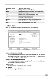
... :Select Item :Select Menu +/-:Change Values Enter:Select Sub-Menu F9:Setup Defaults F10:Save & Exit System Date [Month/Day/Year] Set the system date that you specify. VERSION 3.31a Security Power Boot Exit Mar 22 2004 Mon 20:07:40 [ Setup Help ] Month: Jan - Main Advanced System Date System Time Floppy Drives IDE Devices BIOS Version Processor Type Processor Speed L1 Cache Size L2 Cache Size Total Memory DDR1 DDR2 AMIBIOS SETUP UTILITY - Floppy Drives Use this to 2099...
... :Select Item :Select Menu +/-:Change Values Enter:Select Sub-Menu F9:Setup Defaults F10:Save & Exit System Date [Month/Day/Year] Set the system date that you specify. VERSION 3.31a Security Power Boot Exit Mar 22 2004 Mon 20:07:40 [ Setup Help ] Month: Jan - Main Advanced System Date System Time Floppy Drives IDE Devices BIOS Version Processor Type Processor Speed L1 Cache Size L2 Cache Size Total Memory DDR1 DDR2 AMIBIOS SETUP UTILITY - Floppy Drives Use this to 2099...
User Manual
Page 21
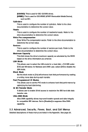
... [Disabled] to determine the correct value. Refer to the drive documentation to suppress Ultra DMA capability. 3.3 Advanced, Security, Power, Boot, and Exit Menus Detailed descriptions of cylinders. Fast Programmed I/O Modes This allows user to set the PIO mode to enhance hard disk performance by optimizing the hard disk timing. 32 Bit Transfer Mode It allows user to enable 32-bit access to configure the number of these menus are listed...
... [Disabled] to determine the correct value. Refer to the drive documentation to suppress Ultra DMA capability. 3.3 Advanced, Security, Power, Boot, and Exit Menus Detailed descriptions of cylinders. Fast Programmed I/O Modes This allows user to set the PIO mode to enhance hard disk performance by optimizing the hard disk timing. 32 Bit Transfer Mode It allows user to enable 32-bit access to configure the number of these menus are listed...
User Manual
Page 22
... folder in the Support CD to visit ASRock's website at http://www.asrock.com; You can find the file through the following path: ..\ MPEGAV \ AVSEQ01.DAT To see this chapter for more about ASRock, welcome to display the menus. 4.2.2 Drivers Menu The Drivers Menu shows the available devices drivers if the system detects installed devices. Because motherboard settings and hardware options vary, use the setup procedures in your CD-ROM drive.
... folder in the Support CD to visit ASRock's website at http://www.asrock.com; You can find the file through the following path: ..\ MPEGAV \ AVSEQ01.DAT To see this chapter for more about ASRock, welcome to display the menus. 4.2.2 Drivers Menu The Drivers Menu shows the available devices drivers if the system detects installed devices. Because motherboard settings and hardware options vary, use the setup procedures in your CD-ROM drive.
User Manual
Page 23
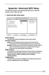
...)]. CPU Host Frequency: [Auto]: It is [Disabled]. You may cause problems during operation. DRAM Frequency: If set the CPU host frequency manually. Advanced BIOS Setup Menu Main Advanced AMIBIOS SETUP UTILITY - VERSION 3.31a Security Power Boot Exit Spread Spectrum CPU Host Frequency Actual Frequency DRAM Frequency Flexibility Option Disabled Auto 133MHz Auto Disabled [ Setup Help ] to enable or disable the feature of this motherboard determined by the jumper-setting. [Manual]: This allows user to set to select this option is recommended to [Auto], the motherboard will...
...)]. CPU Host Frequency: [Auto]: It is [Disabled]. You may cause problems during operation. DRAM Frequency: If set the CPU host frequency manually. Advanced BIOS Setup Menu Main Advanced AMIBIOS SETUP UTILITY - VERSION 3.31a Security Power Boot Exit Spread Spectrum CPU Host Frequency Actual Frequency DRAM Frequency Flexibility Option Disabled Auto 133MHz Auto Disabled [ Setup Help ] to enable or disable the feature of this motherboard determined by the jumper-setting. [Manual]: This allows user to set to select this option is recommended to [Auto], the motherboard will...

User Manual
Page 24
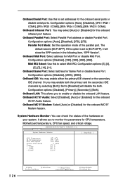
...bit ISA cards. The default value is recommended to select AGP Mode: 4X, 2X, 1X. Chipset Configuration: Advanced AMIBIOS SETUP UTILITY - It is [Normal]. 24 Configuration options: [Auto],[3.0],[2.5], [2]. Please do not select [None] if AGP or PCI graphics card is not inserted. VERSION 3.31a Chipset Configuration [ Setup Help ] AGP Mode AGP Aperture Size AGP Fast Write Onboard VGA Share Memory PCI Delay Transaction USB Controller USB Device Legacy Support SDRAM CAS# Latency Over Vcore Voltage VCCM Voltage V-Link Speed Auto 128MB Disabled Auto Disabled Enabled Disabled Auto...
...bit ISA cards. The default value is recommended to select AGP Mode: 4X, 2X, 1X. Chipset Configuration: Advanced AMIBIOS SETUP UTILITY - It is [Normal]. 24 Configuration options: [Auto],[3.0],[2.5], [2]. Please do not select [None] if AGP or PCI graphics card is not inserted. VERSION 3.31a Chipset Configuration [ Setup Help ] AGP Mode AGP Aperture Size AGP Fast Write Onboard VGA Share Memory PCI Delay Transaction USB Controller USB Device Legacy Support SDRAM CAS# Latency Over Vcore Voltage VCCM Voltage V-Link Speed Auto 128MB Disabled Auto Disabled Enabled Disabled Auto...
User Manual
Page 25
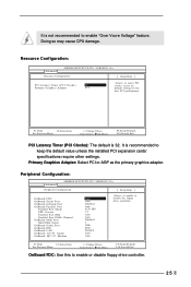
... Graphics Adapter PCI to enable or disable floppy drive controller. 25 F1:Help Esc:Previous Menu :Select Item +/-:Change Values Enter:Select Sub-Menu F9:Setup Defaults F10:Save & Exit OnBoard FDC: Use this to select PCI clocks. VERSION 3.31a Peripheral Configuration [ Setup Help ] OnBoard FDC OnBoard Serial Port OnBoard Infrared Port OnBoard Parallel Port Parallel Port Mode EPP Version Parallel Port IRQ Parallel Port DMA Channel OnBoard Midi Port Midi IRQ Select OnBoard Game Port OnBoard IDE OnBoard LAN OnBoard AC' 97 Audio OnBoard MC' 97 Modem Auto Auto Disabled Auto...
... Graphics Adapter PCI to enable or disable floppy drive controller. 25 F1:Help Esc:Previous Menu :Select Item +/-:Change Values Enter:Select Sub-Menu F9:Setup Defaults F10:Save & Exit OnBoard FDC: Use this to select PCI clocks. VERSION 3.31a Peripheral Configuration [ Setup Help ] OnBoard FDC OnBoard Serial Port OnBoard Infrared Port OnBoard Parallel Port Parallel Port Mode EPP Version Parallel Port IRQ Parallel Port DMA Channel OnBoard Midi Port Midi IRQ Select OnBoard Game Port OnBoard IDE OnBoard LAN OnBoard AC' 97 Audio OnBoard MC' 97 Modem Auto Auto Disabled Auto...
User Manual
Page 26
... +/-:Change Values Enter:Select Sub-Menu F9:Setup Defaults F10:Save & Exit Configuration options: [Auto], [Disabled], [3F8 / IRQ4 / COM1], [2F8 / IRQ3 / COM2], [3E8 / IRQ4 / COM3], [2E8 / IRQ3 / COM4]. OnBoard IDE: You may select [Auto] or [Disabled] for Game Port or disable Game Port. OnBoard Serial Port: Use this to enable or disable the onboard LAN feature. OnBoard Game Port: Select address for this onboard infrared port feature. OnBoard LAN: This allows you to set to monitor the parameters for CPU temperature, Motherboard temperature, CPU fan speed, and critical voltage...
... +/-:Change Values Enter:Select Sub-Menu F9:Setup Defaults F10:Save & Exit Configuration options: [Auto], [Disabled], [3F8 / IRQ4 / COM1], [2F8 / IRQ3 / COM2], [3E8 / IRQ4 / COM3], [2E8 / IRQ3 / COM4]. OnBoard IDE: You may select [Auto] or [Disabled] for Game Port or disable Game Port. OnBoard Serial Port: Use this to enable or disable the onboard LAN feature. OnBoard Game Port: Select address for this onboard infrared port feature. OnBoard LAN: This allows you to set to monitor the parameters for CPU temperature, Motherboard temperature, CPU fan speed, and critical voltage...
User Manual
Page 28
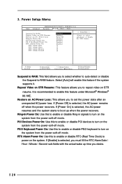
... Clock) to turn on the system. RTC Alarm Power On: Use this to enable or disable PS/2 keyboard to power on the system from the power-soft-off mode. VERSION 3.31a Security Power Boot Exit Suspend To RAM Repost Video on STR Resume Restore on the system from the power-soft-off when the power recovers. F1:Help Esc:Exit :Select Item :Select Menu +/-:Change Values Enter:Select Sub-Menu F9:Setup Defaults...
... Clock) to turn on the system. RTC Alarm Power On: Use this to enable or disable PS/2 keyboard to power on the system from the power-soft-off mode. VERSION 3.31a Security Power Boot Exit Suspend To RAM Repost Video on STR Resume Restore on the system from the power-soft-off when the power recovers. F1:Help Esc:Exit :Select Item :Select Menu +/-:Change Values Enter:Select Sub-Menu F9:Setup Defaults...
User Manual
Page 29
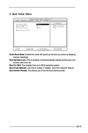
... speed up the boot-up to enable or disable "boot from network" feature. Boot Device Priority F1:Help Esc:Exit :Select Item :Select Menu +/-:Change Values Enter:Select Sub-Menu F9:Setup Defaults F10:Save & Exit Quick Boot Mode: Enable this mode will automatically activate the Numeric Lock function after boot-up. Boot Setup Menu Main Advanced AMIBIOS SETUP UTILITY - VERSION 3.31a Security Power Boot Exit Quick Boot Mode Boot Up Num-Lock Boot To OS/2 Boot From Network Enabled On No Disabled [ Setup Help ] to set the boot device...
... speed up the boot-up to enable or disable "boot from network" feature. Boot Device Priority F1:Help Esc:Exit :Select Item :Select Menu +/-:Change Values Enter:Select Sub-Menu F9:Setup Defaults F10:Save & Exit Quick Boot Mode: Enable this mode will automatically activate the Numeric Lock function after boot-up. Boot Setup Menu Main Advanced AMIBIOS SETUP UTILITY - VERSION 3.31a Security Power Boot Exit Quick Boot Mode Boot Up Num-Lock Boot To OS/2 Boot From Network Enabled On No Disabled [ Setup Help ] to set the boot device...
Quick Installation Guide
Page 2
... JR1 jumper 27 PCI slots (PCI 1- 2) 29 Internal audio connector: CD1 (Black) 31 LAN PHY 2 FID Jumpers (FID0, FID1, FID2, FID3, FID4) 4 CPU socket 6 184-pin DDR DIMM slots (DDR 1- 2) 8 FSB select jumpers (FSB_SEL1) 10 Primary IDE connector (IDE1, Blue) 12 South Bridge controller 14 Chassis fan connector (CHA_FAN1) 16 Power LED Connector (PWR_LED1) 18 Clear CMOS (CLRCMOS2, 2-pin jumper) 20 USB 2.0 header (USB45, Blue) 22 AMR slot (AMR1) 24 JL1 jumper 26 Front panel audio connector (AUDIO1) 28 AUDIO CODEC 30 Internal audio connector: AUX1 (White) 2 ASRock K7VM3 Motherboard
... JR1 jumper 27 PCI slots (PCI 1- 2) 29 Internal audio connector: CD1 (Black) 31 LAN PHY 2 FID Jumpers (FID0, FID1, FID2, FID3, FID4) 4 CPU socket 6 184-pin DDR DIMM slots (DDR 1- 2) 8 FSB select jumpers (FSB_SEL1) 10 Primary IDE connector (IDE1, Blue) 12 South Bridge controller 14 Chassis fan connector (CHA_FAN1) 16 Power LED Connector (PWR_LED1) 18 Clear CMOS (CLRCMOS2, 2-pin jumper) 20 USB 2.0 header (USB45, Blue) 22 AMR slot (AMR1) 24 JL1 jumper 26 Front panel audio connector (AUDIO1) 28 AUDIO CODEC 30 Internal audio connector: AUX1 (White) 2 ASRock K7VM3 Motherboard
Quick Installation Guide
Page 4
... DMA Mode 6; Chassis fan tachometer PCI slots: 2 slots with robust design conforming to ASRock's commitment to 4 IDE devices Floppy Port: Supports 2 floppy disk drives Audio: 5.1 channels AC'97 Audio LAN: Speed: 802.3u (10/100 Ethernet), supports Wake-On-LAN Hardware Monitor: CPU temperature sensing; You may find the latest memory and CPU support lists on ASRock website without notice. It delivers excellent performance with PCI Specification 2.2 AGP slot: 1 AGP slot, supports 1.5V, 4X AGP card (see CAUTION 1); Chassis temperature sensing; This Quick Installation Guide...
... DMA Mode 6; Chassis fan tachometer PCI slots: 2 slots with robust design conforming to ASRock's commitment to 4 IDE devices Floppy Port: Supports 2 floppy disk drives Audio: 5.1 channels AC'97 Audio LAN: Speed: 802.3u (10/100 Ethernet), supports Wake-On-LAN Hardware Monitor: CPU temperature sensing; You may find the latest memory and CPU support lists on ASRock website without notice. It delivers excellent performance with PCI Specification 2.2 AGP slot: 1 AGP slot, supports 1.5V, 4X AGP card (see CAUTION 1); Chassis temperature sensing; This Quick Installation Guide...
Quick Installation Guide
Page 5
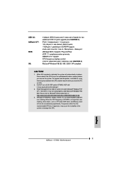
... Memory clock will automatically shutdown. English 5 ASRock K7VM3 Motherboard CPU frequency stepless control (only for USB 2.0 works fine under Microsoft® Windows® 98/ ME. Please check if the CPU fan on K7VM3's AGP slot! It may not work properly under Microsoft® Windows® XP SP1 / 2000 SP4. USB 2.0: ASRock I/OTM: BIOS: OS: 4 default USB 2.0 ports and 1 extra set to perform over clocking. Supports "Plug and Play"; Please refer to perform over clocking, other than the recommended CPU bus frequencies...
... Memory clock will automatically shutdown. English 5 ASRock K7VM3 Motherboard CPU frequency stepless control (only for USB 2.0 works fine under Microsoft® Windows® 98/ ME. Please check if the CPU fan on K7VM3's AGP slot! It may not work properly under Microsoft® Windows® XP SP1 / 2000 SP4. USB 2.0: ASRock I/OTM: BIOS: OS: 4 default USB 2.0 ports and 1 extra set to perform over clocking. Supports "Plug and Play"; Please refer to perform over clocking, other than the recommended CPU bus frequencies...

Quick Installation Guide
Page 10
... end Connect this USB 2.0 header is available to support 2 additional USB 2.0 ports. Internal audio connectors (4-pin CD1, 4-pin AUX1) (CD1: see p.2 item 29) (AUX1: see p.2 item 20) ASRock I/OTM already provided 4 default USB 2.0 ports. DO NOT place jumper caps over these connectors. 2.5 Connectors Connectors are not sufficient, this BLACK end to the motherboard to the IDE devices 80-Pin ATA 100/133 cable Note:To optimize compatibility and performance, please connect your hard disk drive to the primary IDE connector (IDE1...
... end Connect this USB 2.0 header is available to support 2 additional USB 2.0 ports. Internal audio connectors (4-pin CD1, 4-pin AUX1) (CD1: see p.2 item 29) (AUX1: see p.2 item 20) ASRock I/OTM already provided 4 default USB 2.0 ports. DO NOT place jumper caps over these connectors. 2.5 Connectors Connectors are not sufficient, this BLACK end to the motherboard to the IDE devices 80-Pin ATA 100/133 cable Note:To optimize compatibility and performance, please connect your hard disk drive to the primary IDE connector (IDE1...
Quick Installation Guide
Page 11
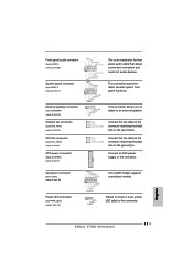
... the black wire to the connector. Connect an ATX power supply to the ground pin. English 11 ASRock K7VM3 Motherboard Connect the fan cable to the connector matching the black wire to this connector. This COM1 header supports a serial port module. Please connect a 3-pin power LED cable to the ground pin. Front panel audio connector (9-pin AUDIO1) (see p.2 item 26) System panel connector (9-pin PANEL1) (see p.2 item 17) External speaker connector (4-pin SPEAKER1) (see p.2 item 15) Chassis fan connector (3-pin CHA_FAN1) (see p.2 item 14) CPU fan connector (3-pin CPU_FAN1) (see...
... the black wire to the connector. Connect an ATX power supply to the ground pin. English 11 ASRock K7VM3 Motherboard Connect the fan cable to the connector matching the black wire to this connector. This COM1 header supports a serial port module. Please connect a 3-pin power LED cable to the ground pin. Front panel audio connector (9-pin AUDIO1) (see p.2 item 26) System panel connector (9-pin PANEL1) (see p.2 item 17) External speaker connector (4-pin SPEAKER1) (see p.2 item 15) Chassis fan connector (3-pin CHA_FAN1) (see p.2 item 14) CPU fan connector (3-pin CPU_FAN1) (see...
Quick Installation Guide
Page 12
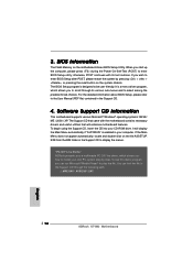
..., you start up the computer, please press during the Power-On-Self-Test (POST) to scroll through the following path: ..\ MPEGAV \ AVSEQ01.DAT 12 ASRock K7VM3 Motherboard English The BIOS Setup program is a menu-driven program, which shows you to enter BIOS Setup utility; When you can find the file in the Support CD. 4. EXE from the BIN folder in the Support CD to the User Manual (PDF file) contained...
..., you start up the computer, please press during the Power-On-Self-Test (POST) to scroll through the following path: ..\ MPEGAV \ AVSEQ01.DAT 12 ASRock K7VM3 Motherboard English The BIOS Setup program is a menu-driven program, which shows you to enter BIOS Setup utility; When you can find the file in the Support CD. 4. EXE from the BIN folder in the Support CD to the User Manual (PDF file) contained...


