

User Manual
Page 5
.... In this manual will be subject to the hardware installation. You may find the latest memory and CPU support lists on ASRock website without notice. Chapter 3 and 4 contain the configuration guide to quality and endurance. In case any modifications of the ...occur, the updated version will be available on ASRock website as well. ASRock website http://www.asrock.com 1.1 Package Contents ASRock K7Upgrade-600 Motherboard (ATX Form Factor: 12.0-in x 8.2-in, 30.5 cm x 20.8 cm) ASRock K7Upgrade-600 Quick Installation Guide ASRock K7Upgrade-600 Support CD One 80-conductor Ultra ATA 66/...
.... In this manual will be subject to the hardware installation. You may find the latest memory and CPU support lists on ASRock website without notice. Chapter 3 and 4 contain the configuration guide to quality and endurance. In case any modifications of the ...occur, the updated version will be available on ASRock website as well. ASRock website http://www.asrock.com 1.1 Package Contents ASRock K7Upgrade-600 Motherboard (ATX Form Factor: 12.0-in x 8.2-in, 30.5 cm x 20.8 cm) ASRock K7Upgrade-600 Quick Installation Guide ASRock K7Upgrade-600 Support CD One 80-conductor Ultra ATA 66/...

Quick Installation Guide
Page 1
... this device must accept any kind, either expressed or implied, including but not limited to the contents of this guide, ASRock does not provide warranty of any interference received, including interference that may not be registered trademarks or copyrights of their respective... constructed as a commitment by the purchaser for any errors or omissions that may cause undesired operation. All rights reserved. 1 ASRock K7Upgrade-600 Motherboard English Products and corporate names appearing in this guide may or may appear in this guide. Disclaimer: Specifications and information ...
... this device must accept any kind, either expressed or implied, including but not limited to the contents of this guide, ASRock does not provide warranty of any interference received, including interference that may not be registered trademarks or copyrights of their respective... constructed as a commitment by the purchaser for any errors or omissions that may cause undesired operation. All rights reserved. 1 ASRock K7Upgrade-600 Motherboard English Products and corporate names appearing in this guide may or may appear in this guide. Disclaimer: Specifications and information ...

Quick Installation Guide
Page 2
... ) 32 J6 Jumper ( 5 x 2-Pin ) 33 AGP Slot ( 1.5V_AGP1 ) 34 Internal Audio Connector: CD1 ( Black ) 35 Internal Audio Connector: AUX1 ( White ) 36 ATX Power Connector ( ATXPWR1 ) 2 ASRock K7Upgrade-600 Motherboard
... ) 32 J6 Jumper ( 5 x 2-Pin ) 33 AGP Slot ( 1.5V_AGP1 ) 34 Internal Audio Connector: CD1 ( Black ) 35 Internal Audio Connector: AUX1 ( White ) 36 ATX Power Connector ( ATXPWR1 ) 2 ASRock K7Upgrade-600 Motherboard
Quick Installation Guide
Page 3
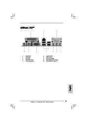
ASRock I/OTM 1 Parallel Port 2 RJ-45 Port 3 Game Port 4 Microphone (Pink) 5 Line In (Light Blue) 6 Line Out (Lime) 7 USB 2.0 Ports 8 Serial Port (COM1) 9 PS/2 Keyboard Port (Purple) 10 PS/2 Mouse Port (Green) English 3 ASRock K7Upgrade-600 Motherboard
ASRock I/OTM 1 Parallel Port 2 RJ-45 Port 3 Game Port 4 Microphone (Pink) 5 Line In (Light Blue) 6 Line Out (Lime) 7 USB 2.0 Ports 8 Serial Port (COM1) 9 PS/2 Keyboard Port (Purple) 10 PS/2 Mouse Port (Green) English 3 ASRock K7Upgrade-600 Motherboard
Quick Installation Guide
Page 4
... BIOS software might be updated, the content of the motherboard and step-bystep installation guide. 1. ASRock website http://www.asrock.com 1.1 Package Contents ASRock K7Upgrade-600 Motherboard (ATX Form Factor: 12.0-in x 8.2-in, 30.5 cm x 20.8 cm) ASRock K7Upgrade-600 Quick Installation Guide ASRock K7Upgrade-600 Support CD One 80-conductor Ultra ATA 66/100/133 IDE Ribbon Cable One Ribbon...
... BIOS software might be updated, the content of the motherboard and step-bystep installation guide. 1. ASRock website http://www.asrock.com 1.1 Package Contents ASRock K7Upgrade-600 Motherboard (ATX Form Factor: 12.0-in x 8.2-in, 30.5 cm x 20.8 cm) ASRock K7Upgrade-600 Quick Installation Guide ASRock K7Upgrade-600 Support CD One 80-conductor Ultra ATA 66/100/133 IDE Ribbon Cable One Ribbon...

Quick Installation Guide
Page 5
...: Speed: 802.3u (10/100 Ethernet), supports Wake-On-LAN Hardware Monitor: CPU Temperature Sensing Motherboard Temperature Sensing CPU Overheat Shutdown to Protect CPU Life (ASRock U-COP)(see CAUTION 1) CPU Fan Tachometer Chassis Fan Tachometer Voltage Monitoring: +12V, +5V, +3.3V, Vcore K8 Bridge: Supports CPU upgrade from AMD K7...USB 2.0: 8 USB 2.0 ports: include 4 ready-to-use USB 2.0 ports on the rear panel, plus two on-board header supporting 4 extra USB 2.0 ports (see CAUTION 3) ASRock I/O: 1 PS/2 mouse port, 1 PS/2 keyboard port, English 5 ASRock K7Upgrade-600 Motherboard
...: Speed: 802.3u (10/100 Ethernet), supports Wake-On-LAN Hardware Monitor: CPU Temperature Sensing Motherboard Temperature Sensing CPU Overheat Shutdown to Protect CPU Life (ASRock U-COP)(see CAUTION 1) CPU Fan Tachometer Chassis Fan Tachometer Voltage Monitoring: +12V, +5V, +3.3V, Vcore K8 Bridge: Supports CPU upgrade from AMD K7...USB 2.0: 8 USB 2.0 ports: include 4 ready-to-use USB 2.0 ports on the rear panel, plus two on-board header supporting 4 extra USB 2.0 ports (see CAUTION 3) ASRock I/O: 1 PS/2 mouse port, 1 PS/2 keyboard port, English 5 ASRock K7Upgrade-600 Motherboard

Quick Installation Guide
Page 6
... use a 3.3V AGP card on the motherboard functions properly and unplug the power cord, then plug it is not recommended to perform over clocking. English 6 ASRock K7Upgrade-600 Motherboard Please check page 26 of this motherboard! It may cause the instability of this motherboard offers stepless control, it back again. The CPU host...
... use a 3.3V AGP card on the motherboard functions properly and unplug the power cord, then plug it is not recommended to perform over clocking. English 6 ASRock K7Upgrade-600 Motherboard Please check page 26 of this motherboard! It may cause the instability of this motherboard offers stepless control, it back again. The CPU host...

Quick Installation Guide
Page 7
... touch the ICs. 4. When placing screws into the screw holes to secure the motherboard to static electricity, NEVER place your CPU fan and heatsink vendors. 7 ASRock K7Upgrade-600 Motherboard English 2. Also remember to use a grounded wrist strap or touch a safety grounded object before touching any motherboard settings. 1. The lever clicks on the socket...
... touch the ICs. 4. When placing screws into the screw holes to secure the motherboard to static electricity, NEVER place your CPU fan and heatsink vendors. 7 ASRock K7Upgrade-600 Motherboard English 2. Also remember to use a grounded wrist strap or touch a safety grounded object before touching any motherboard settings. 1. The lever clicks on the socket...
Quick Installation Guide
Page 8
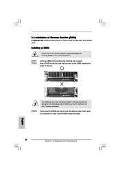
2.2 Installation of Memory Modules (DIMM) K7Upgrade-600 motherboard provides two 184-pin DDR (Double Data Rate) DIMM slots. STEP 3: Firmly insert the DIMM into the slot at both ends fully snap back ... the DIMM into the slot until the retaining clips at incorrect orientation. English The DIMM only fits in place and the DIMM is properly seated. 8 ASRock K7Upgrade-600 Motherboard It will cause permanent damage to disconnect power supply before adding or removing DIMMs or the system components. STEP 1: STEP 2: Unlock a DIMM slot by...
2.2 Installation of Memory Modules (DIMM) K7Upgrade-600 motherboard provides two 184-pin DDR (Double Data Rate) DIMM slots. STEP 3: Firmly insert the DIMM into the slot at both ends fully snap back ... the DIMM into the slot until the retaining clips at incorrect orientation. English The DIMM only fits in place and the DIMM is properly seated. 8 ASRock K7Upgrade-600 Motherboard It will cause permanent damage to disconnect power supply before adding or removing DIMMs or the system components. STEP 1: STEP 2: Unlock a DIMM slot by...

Quick Installation Guide
Page 9
... 2, No. 10) J11 / J13 / J16 (page 2, No. 14) (8 x 2-pin; short pin1, pin2) 754-Pin CPU J14 (page 2, No. 9) (Using an add-on K7Upgrade-600 motherboard. open ) J 6 (page 2, No. 32) J12 (page 2, No. 12) J7 / J8 / J9 (page 2, No. 12) (5 x 2-pin; K8 Bridge (Orange-Colored...adjust the jumper settings for the correct jumper settings. short pin1, pin2) (4 x 3-pin; open ) (1 x 3-pin; short pin2, pin3) 9 ASRock K7Upgrade-600 Motherboard English short ) (4 x 3-pin; The orange-colored Bridge (K8BRIDGE_1) is not an AGP slot, and the brown-colored Bridge (K8BRIDGE_2) is ...
... 2, No. 10) J11 / J13 / J16 (page 2, No. 14) (8 x 2-pin; short pin1, pin2) 754-Pin CPU J14 (page 2, No. 9) (Using an add-on K7Upgrade-600 motherboard. open ) J 6 (page 2, No. 32) J12 (page 2, No. 12) J7 / J8 / J9 (page 2, No. 12) (5 x 2-pin; K8 Bridge (Orange-Colored...adjust the jumper settings for the correct jumper settings. short pin1, pin2) (4 x 3-pin; open ) (1 x 3-pin; short pin2, pin3) 9 ASRock K7Upgrade-600 Motherboard English short ) (4 x 3-pin; The orange-colored Bridge (K8BRIDGE_1) is not an AGP slot, and the brown-colored Bridge (K8BRIDGE_2) is ...
Quick Installation Guide
Page 10
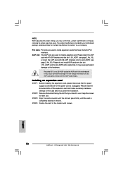
...), or insert the AGP card with the slot and press firmly until the card is bundled in your AGP card, please check with screws. 10 ASRock K7Upgrade-600 Motherboard English Installing an expansion card STEP 1: Before installing the expansion card, please make necessary hardware settings for later use it properly. Please read the...
...), or insert the AGP card with the slot and press firmly until the card is bundled in your AGP card, please check with screws. 10 ASRock K7Upgrade-600 Motherboard English Installing an expansion card STEP 1: Before installing the expansion card, please make necessary hardware settings for later use it properly. Please read the...

Quick Installation Guide
Page 11
..., the jumper is "Short". Clear CMOS (CLRCMOS2) (see p.2, No. 27) Note: If the jumpers JL1 and JR1 are setup. After waiting for 5 seconds. English 11 ASRock K7Upgrade-600 Motherboard 2.4 Jumpers Setup The illustration shows how jumpers are short, both the front panel and the rear panel audio connectors can work.
..., the jumper is "Short". Clear CMOS (CLRCMOS2) (see p.2, No. 27) Note: If the jumpers JL1 and JR1 are setup. After waiting for 5 seconds. English 11 ASRock K7Upgrade-600 Motherboard 2.4 Jumpers Setup The illustration shows how jumpers are short, both the front panel and the rear panel audio connectors can work.

Quick Installation Guide
Page 12
... must set the FSB jumper according to your AMD CPU before you use the "Manual" option as the FSB setting in the Support CD. 12 ASRock K7Upgrade-600 Motherboard English For detailed information, please refer to adjust the multiplier of jumper-setting. CPU Multiplier Jumper (J1, 5 x 3-pin) (see p.2, No. 13) Note: The setting...
... must set the FSB jumper according to your AMD CPU before you use the "Manual" option as the FSB setting in the Support CD. 12 ASRock K7Upgrade-600 Motherboard English For detailed information, please refer to adjust the multiplier of jumper-setting. CPU Multiplier Jumper (J1, 5 x 3-pin) (see p.2, No. 13) Note: The setting...

Quick Installation Guide
Page 13
.... 16) SATA2 SATA1 These two Serial ATA (SATA) connectors support SATA data cables for the details. Besides, to the instruction of the motherboard! English 13 ASRock K7Upgrade-600 Motherboard Please refer to optimize compatibility and performance, please connect your IDE device vendor for internal storage devices. Placing jumper caps over these headers and...
.... 16) SATA2 SATA1 These two Serial ATA (SATA) connectors support SATA data cables for the details. Besides, to the instruction of the motherboard! English 13 ASRock K7Upgrade-600 Motherboard Please refer to optimize compatibility and performance, please connect your IDE device vendor for internal storage devices. Placing jumper caps over these headers and...

Quick Installation Guide
Page 14
USB 2.0 Header (9-pin USB45) (see p.2, No. 23) ASRock I /O provides you 4 ready-to support 4 extra USB 2.0 ports Infrared Module Header (5-pin IR1) (see p.2, No. 26) These connectors allow you 4 ready-to receive stereo audio ... module. This is available to the power connector of the power supply. USB 2.0 Header (9-pin USB67) (see p.2, No. 22) ASRock I /O provides you to -use USB 2.0 ports on the drive. English 14 ASRock K7Upgrade-600 Motherboard If the rear USB ports are not sufficient, this USB 2.0 header is available to -use USB 2.0 ports on the...
USB 2.0 Header (9-pin USB45) (see p.2, No. 23) ASRock I /O provides you 4 ready-to support 4 extra USB 2.0 ports Infrared Module Header (5-pin IR1) (see p.2, No. 26) These connectors allow you 4 ready-to receive stereo audio ... module. This is available to the power connector of the power supply. USB 2.0 Header (9-pin USB67) (see p.2, No. 22) ASRock I /O provides you to -use USB 2.0 ports on the drive. English 14 ASRock K7Upgrade-600 Motherboard If the rear USB ports are not sufficient, this USB 2.0 header is available to -use USB 2.0 ports on the...

Quick Installation Guide
Page 15
... fan cable to the ground pin. Please connect an ATX power supply to this connector and match the black wire to this connector. English 15 ASRock K7Upgrade-600 Motherboard System Panel Header (9-pin PANEL1) (see p.2, No. 20) Chassis Speaker Header (4-pin SPEAKER 1) (see p.2, No. 21) Chassis Fan Connector (3-pin CHA_FAN1) (see p.2, No. 19...
... fan cable to the ground pin. Please connect an ATX power supply to this connector and match the black wire to this connector. English 15 ASRock K7Upgrade-600 Motherboard System Panel Header (9-pin PANEL1) (see p.2, No. 20) Chassis Speaker Header (4-pin SPEAKER 1) (see p.2, No. 21) Chassis Fan Connector (3-pin CHA_FAN1) (see p.2, No. 19...

Quick Installation Guide
Page 16
... Hot Plug and Hot Swap functions for the action to the motherboard's SATA connector. NOTE What is still power-on and in working condition. 16 ASRock K7Upgrade-600 Motherboard English STEP 4: Connect the other end of the SATA data cable to insert and remove the SATA HDDs while the system is Hot Plug...
... Hot Plug and Hot Swap functions for the action to the motherboard's SATA connector. NOTE What is still power-on and in working condition. 16 ASRock K7Upgrade-600 Motherboard English STEP 4: Connect the other end of the SATA data cable to insert and remove the SATA HDDs while the system is Hot Plug...

Quick Installation Guide
Page 17
... Please insert a floppy diskette into the floppy drive at this moment!) STEP 2: During POST at the following path: .. \ VIA RAID Tool 17 ASRock K7Upgrade-600 Motherboard English STEP 5: The system will start the OS installation. Please refer to the document in the Support CD, "Guide to VIA RAID Tool", which...into the floppy drive. WARNING! 2.8 Making An SATA Driver Diskette If you want to format and copy files [YN]? STEP 1: Insert the ASRock Support CD into your optical drive to boot your SATA HDDs, you will need to check the installation guide in Windows environment.
... Please insert a floppy diskette into the floppy drive at this moment!) STEP 2: During POST at the following path: .. \ VIA RAID Tool 17 ASRock K7Upgrade-600 Motherboard English STEP 5: The system will start the OS installation. Please refer to the document in the Support CD, "Guide to VIA RAID Tool", which...into the floppy drive. WARNING! 2.8 Making An SATA Driver Diskette If you want to format and copy files [YN]? STEP 1: Insert the ASRock Support CD into your optical drive to boot your SATA HDDs, you will need to check the installation guide in Windows environment.

Quick Installation Guide
Page 18
... Utility. The Support CD that came with its various sub-menus and to scroll through the following path: ..\ MPEGAV \ AVSEQ01.DAT 18 ASRock K7Upgrade-600 Motherboard English You can run Microsoft® Media Player® to be user-friendly. It will enhance motherboard features. If the Main Menu ...file "ASSETUP.EXE" from the BIN folder in the Support CD. 4. It is designed to play the file. "PC-DIY Live Demo" ASRock presents you a multimedia PC-DIY live demo, which allows you wish to install your CD-ROM drive. Software Support CD information This motherboard supports...
... Utility. The Support CD that came with its various sub-menus and to scroll through the following path: ..\ MPEGAV \ AVSEQ01.DAT 18 ASRock K7Upgrade-600 Motherboard English You can run Microsoft® Media Player® to be user-friendly. It will enhance motherboard features. If the Main Menu ...file "ASSETUP.EXE" from the BIN folder in the Support CD. 4. It is designed to play the file. "PC-DIY Live Demo" ASRock presents you a multimedia PC-DIY live demo, which allows you wish to install your CD-ROM drive. Software Support CD information This motherboard supports...

Quick Installation Guide
Page 19
19 ASRock K7Upgrade-600 Motherboard
19 ASRock K7Upgrade-600 Motherboard


