
User Manual
Page 7
... 1 AUDIO1 JL1 10 JR1 27 26 AGP1 11 Audio CODEC 25 LAN PHY PCI 1 K7S8XE+ PCI 2 SiS 964 12 24 Super I/O PCI 3 PCI 4 13 CHA_FAN1 14 CMOS Battery 15 SATA1 SATA2 23 2MB BIOS ATA133 AGP 8X SATA DDR400 FLOPPY1 16 17 PCI 5 CLRCMOS2 5.1 CH PANEL 1 PLED ...PWRBTN 1 GAME1 USB 2.0 1 USB67 1 IR1 1 SPEAKER1 1 HDLED RESET 22 21 20 19 18 1 PS2_USB_PWR1 Jumper 2 CPU Fan Connector (CPU_FAN1) 3 CPU...
... 1 AUDIO1 JL1 10 JR1 27 26 AGP1 11 Audio CODEC 25 LAN PHY PCI 1 K7S8XE+ PCI 2 SiS 964 12 24 Super I/O PCI 3 PCI 4 13 CHA_FAN1 14 CMOS Battery 15 SATA1 SATA2 23 2MB BIOS ATA133 AGP 8X SATA DDR400 FLOPPY1 16 17 PCI 5 CLRCMOS2 5.1 CH PANEL 1 PLED ...PWRBTN 1 GAME1 USB 2.0 1 USB67 1 IR1 1 SPEAKER1 1 HDLED RESET 22 21 20 19 18 1 PS2_USB_PWR1 Jumper 2 CPU Fan Connector (CPU_FAN1) 3 CPU...

User Manual
Page 13
... jumper according to clear the data in CMOS. Please follow the figures above to remove the jumper cap after clearing the CMOS. To clear and reset the system parameters to default setup, please turn off the computer and unplug the power cord, then use the "Manual" option as the FSB setting... to enable (see p.7 item 27) JR1 JL1 Note: If the jumpers JL1 and JR1 are setup. The data in BIOS setup to clear the CMOS when you just finish updating the BIOS, you need to perform over clocking. If you must set the CPU front side bus frequency. If no jumper cap...
... jumper according to clear the data in CMOS. Please follow the figures above to remove the jumper cap after clearing the CMOS. To clear and reset the system parameters to default setup, please turn off the computer and unplug the power cord, then use the "Manual" option as the FSB setting... to enable (see p.7 item 27) JR1 JL1 Note: If the jumpers JL1 and JR1 are setup. The data in BIOS setup to clear the CMOS when you just finish updating the BIOS, you need to perform over clocking. If you must set the CPU front side bus frequency. If no jumper cap...

User Manual
Page 19
...configure your screen. 3.1.1 BIOS Menu Bar The top of the Setup Screen is a menu-driven program, which allows you see on your system. You may also restart by pressing the reset button on the motherboard stores the BIOS Setup Utility. Chapter 3 BIOS Setup 3.1 BIOS Setup Utility This section ...explains how to use the BIOS Setup Utility to be user-friendly. The following table lists the keys in...
...configure your screen. 3.1.1 BIOS Menu Bar The top of the Setup Screen is a menu-driven program, which allows you see on your system. You may also restart by pressing the reset button on the motherboard stores the BIOS Setup Utility. Chapter 3 BIOS Setup 3.1 BIOS Setup Utility This section ...explains how to use the BIOS Setup Utility to be user-friendly. The following table lists the keys in...

User Manual
Page 7
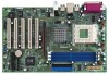
... 01 23 45 AGP1 PCI 1 PCI 2 SiS 963L 6 CHA_FAN1 9 8 IDE2 16 7 IDE1 PCI 3 PCI 4 K7S8XE CLRCMOS1 CMOS Battery CLRCMOS2 27 10 FLOPPY1 PCI 5 ` 2MB 11 BIOS PCI 6 ATA133 USB2.0 5.1CH USB45 1 IR1 1 SPEAKER1 1 PANEL 1 PLED PWRBTN 1 HDLED RESET 15 12 13 17 14 1 ATX power connector (ATXPWR1) 2 CPU socket 3 CPU fan connector (CPU_FAN1...
... 01 23 45 AGP1 PCI 1 PCI 2 SiS 963L 6 CHA_FAN1 9 8 IDE2 16 7 IDE1 PCI 3 PCI 4 K7S8XE CLRCMOS1 CMOS Battery CLRCMOS2 27 10 FLOPPY1 PCI 5 ` 2MB 11 BIOS PCI 6 ATA133 USB2.0 5.1CH USB45 1 IR1 1 SPEAKER1 1 PANEL 1 PLED PWRBTN 1 HDLED RESET 15 12 13 17 14 1 ATX power connector (ATXPWR1) 2 CPU socket 3 CPU fan connector (CPU_FAN1...

User Manual
Page 15
...or by turning the system off and then back on the motherboard stores the BIOS Setup Utility. The following BIOS setup screens and descriptions are for reference purpose only, and they may also restart by pressing the reset button on the keyboard until the desired item is highlighted. 3.1.2 Legend Bar ...At the bottom of the screen has a menu bar with their corresponding functions. 15 Please press during the Power-On-Self-Test (POST) to configure your screen. 3.1.1 BIOS Menu Bar ...
...or by turning the system off and then back on the motherboard stores the BIOS Setup Utility. The following BIOS setup screens and descriptions are for reference purpose only, and they may also restart by pressing the reset button on the keyboard until the desired item is highlighted. 3.1.2 Legend Bar ...At the bottom of the screen has a menu bar with their corresponding functions. 15 Please press during the Power-On-Self-Test (POST) to configure your screen. 3.1.1 BIOS Menu Bar ...


