User Manual
Page 3
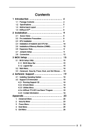
Exit Menu 26 3 Boot Menu 25 5. Security Menu 23 3. Contents 1 Introduction 4 1.1 Package Contents 4 1.2 Specifications 5 1.3 Motherboard Layout 7 1.4 ASRock I/OTM 8 2 Installation 9 2.1 Screw Holes 9 2.2 Pre-installation Precautions 9 2.3 CPU Installation 9 2.4 Installation of Heatsink and CPU fan 10 2.5 Installation... Operating System 19 4.2 Support CD Information 19 4.2.1 Running Support CD 19 4.2.2 Drivers Menu 19 4.2.3 Utilities Menu 19 4.2.4 ASRock "PC-DIY Live Demo" Program 19 4.2.5 Contact Information 19 Appendix 20 1. Power Menu 24 4. Advanced Menu 20 2.
Exit Menu 26 3 Boot Menu 25 5. Security Menu 23 3. Contents 1 Introduction 4 1.1 Package Contents 4 1.2 Specifications 5 1.3 Motherboard Layout 7 1.4 ASRock I/OTM 8 2 Installation 9 2.1 Screw Holes 9 2.2 Pre-installation Precautions 9 2.3 CPU Installation 9 2.4 Installation of Heatsink and CPU fan 10 2.5 Installation... Operating System 19 4.2 Support CD Information 19 4.2.1 Running Support CD 19 4.2.2 Drivers Menu 19 4.2.3 Utilities Menu 19 4.2.4 ASRock "PC-DIY Live Demo" Program 19 4.2.5 Contact Information 19 Appendix 20 1. Power Menu 24 4. Advanced Menu 20 2.
User Manual
Page 4
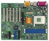
... manual will be subject to quality and endurance. ASRock website http://www.asrock.com 1.1 Package Contents ASRock K7S8X motherboard (ATX form factor: 12" x 9.6", 30.5 x 24.4 cm) ASRock K7S8X Quick Installation Guide ASRock AMD-SiS Series Support CD 1 cable for IDE devices (1 x ATA 66/100/133) 1 cable for purchasing ASRock K7S8X motherboard, a reliable motherboard produced under ASRock's consistently stringent quality control. Chapter 1 and 2 of...
... manual will be subject to quality and endurance. ASRock website http://www.asrock.com 1.1 Package Contents ASRock K7S8X motherboard (ATX form factor: 12" x 9.6", 30.5 x 24.4 cm) ASRock K7S8X Quick Installation Guide ASRock AMD-SiS Series Support CD 1 cable for IDE devices (1 x ATA 66/100/133) 1 cable for purchasing ASRock K7S8X motherboard, a reliable motherboard produced under ASRock's consistently stringent quality control. Chapter 1 and 2 of...
User Manual
Page 6
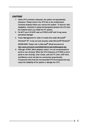
It may cause the instability of K7S8X is set to perform over clocking, other than the recommended CPU bus frequencies may cause permanent damage! 3. Power Management for USB 2.0 works fine under Microsoft&#... and the heatsink when you resume the system. Do NOT use 3.3V AGP card on the motherboard functions properly before you install the PC system. 2. Please check if the CPU fan on K7S8X's AGP slot! Although K7S8X offers stepless control, it is detected, the system will also be overclocked proportionally. To improve heat...
It may cause the instability of K7S8X is set to perform over clocking, other than the recommended CPU bus frequencies may cause permanent damage! 3. Power Management for USB 2.0 works fine under Microsoft&#... and the heatsink when you resume the system. Do NOT use 3.3V AGP card on the motherboard functions properly before you install the PC system. 2. Please check if the CPU fan on K7S8X's AGP slot! Although K7S8X offers stepless control, it is detected, the system will also be overclocked proportionally. To improve heat...
User Manual
Page 9
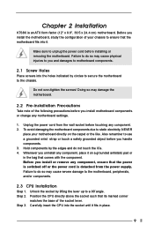
...motherboard components due to the motherboard... the socket by circles to secure the motherboard to use a grounded wrist strap or ....5 x 24.4 cm) motherboard. Step 3. Before you and damages to motherboard components. 2.1 Screw Holes...motherboard settings. 1. Before you uninstall any component, ensure that the motherboard fits into the socket until it . Whenever you install the motherboard, study the configuration of your motherboard... before you install motherboard components or change any component. ... do so may damage the motherboard. 2.2 Pre-installation Precautions Take...
...motherboard components due to the motherboard... the socket by circles to secure the motherboard to use a grounded wrist strap or ....5 x 24.4 cm) motherboard. Step 3. Before you and damages to motherboard components. 2.1 Screw Holes...motherboard settings. 1. Before you uninstall any component, ensure that the motherboard fits into the socket until it . Whenever you install the motherboard, study the configuration of your motherboard... before you install motherboard components or change any component. ... do so may damage the motherboard. 2.2 Pre-installation Precautions Take...
User Manual
Page 10
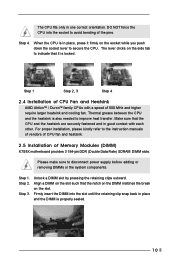
... in place, press it is also needed to secure the CPU. Firmly insert the DIMM into the socket to avoid bending of Memory Modules (DIMM) K7S8X motherboard provides 3 184-pin DDR (Double Data Rate) SDRAM DIMM slots. Step 1. Align a DIMM on the socket while you push down the socket lever to improve...
... in place, press it is also needed to secure the CPU. Firmly insert the DIMM into the socket to avoid bending of Memory Modules (DIMM) K7S8X motherboard provides 3 184-pin DDR (Double Data Rate) SDRAM DIMM slots. Step 1. Align a DIMM on the socket while you push down the socket lever to improve...
User Manual
Page 11
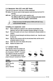
The ASRock AGP slot has a special locking mechanism which can securely fasten the graphics card inserted. Please do not use 3.3v AGP card on the pins, the jumper is placed on K7S8X's AGP slot! Step 2. Remove the system unit cover (if your motherboard is used to install expansion cards that...Slots) There are setup. Replace the system cover. 2.7 Jumpers Setup The illustration shows how jumpers are 6 PCI slots and 1 AGP slot on K7S8X motherboard. The illustration shows a 3-pin jumper whose pin1 and pin2 are used to the chassis with the slot and press firmly until the card is ...
The ASRock AGP slot has a special locking mechanism which can securely fasten the graphics card inserted. Please do not use 3.3v AGP card on the pins, the jumper is placed on K7S8X's AGP slot! Step 2. Remove the system unit cover (if your motherboard is used to install expansion cards that...Slots) There are setup. Replace the system cover. 2.7 Jumpers Setup The illustration shows how jumpers are 6 PCI slots and 1 AGP slot on K7S8X motherboard. The illustration shows a 3-pin jumper whose pin1 and pin2 are used to the chassis with the slot and press firmly until the card is ...
User Manual
Page 12
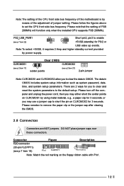
... the computer and unplug the power cord, then you to the default setup. Note:The setting of the CPU front side bus frequency of this motherboard is by using metal material, e.g., a paper clip for 3 seconds; Connector Figure Description FDD connector (33-pin FLOPPY1) (see p.7 item 10) Pin1 FLOPPY1 Red marking Note...
... the computer and unplug the power cord, then you to the default setup. Note:The setting of the CPU front side bus frequency of this motherboard is by using metal material, e.g., a paper clip for 3 seconds; Connector Figure Description FDD connector (33-pin FLOPPY1) (see p.7 item 10) Pin1 FLOPPY1 Red marking Note...
User Manual
Page 13
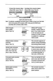
... optional wireless transmitting and receiving infrared module. USB 2.0 header (9-pin USB45) (see p.7 item 8) PIN1 IDE1 BLUE Connect to the motherboard PIN1 IDE2 BLACK Connect to the IDE devices 80-Pin ATA 100/133 cable Note: To optimize compatibility and performance, please connect your ...Secondary IDE connector (Black) (39-pin IDE1, see p.7 item 7) (39-pin IDE2, see p.7 item 13) USB_PWR P-5 P+5 GND DUMMY 1 GND P+4 P-4 USB_PWR ASRock I/OTM already provided 4 default USB 2.0 ports. If the 4 USB 2.0 ports on the rear panel are not sufficient, an USB 2.0 header is an interface for 2...
... optional wireless transmitting and receiving infrared module. USB 2.0 header (9-pin USB45) (see p.7 item 8) PIN1 IDE1 BLUE Connect to the motherboard PIN1 IDE2 BLACK Connect to the IDE devices 80-Pin ATA 100/133 cable Note: To optimize compatibility and performance, please connect your ...Secondary IDE connector (Black) (39-pin IDE1, see p.7 item 7) (39-pin IDE2, see p.7 item 13) USB_PWR P-5 P+5 GND DUMMY 1 GND P+4 P-4 USB_PWR ASRock I/OTM already provided 4 default USB 2.0 ports. If the 4 USB 2.0 ports on the rear panel are not sufficient, an USB 2.0 header is an interface for 2...
User Manual
Page 15
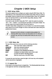
... following table lists the keys in the legend bar with their corresponding functions. 15 You can also restart by pressing the reset button on the motherboard stores the BIOS Setup Utility. Press during the Power-On-Self-Test (POST) to enter the BIOS Setup Utility, otherwise, POST continues with its various...
... following table lists the keys in the legend bar with their corresponding functions. 15 You can also restart by pressing the reset button on the motherboard stores the BIOS Setup Utility. Press during the Power-On-Self-Test (POST) to enter the BIOS Setup Utility, otherwise, POST continues with its various...
User Manual
Page 19
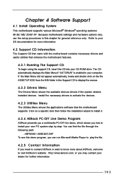
... system detects installed devices. Chapter 4 Software Support 4.1 Install Operating System This motherboard supports various Microsoft® Windows® operating systems: 98 SE/ ME/ 2000/ XP. Refer to your dealer for more about ASRock, welcome to install your own PC system step by step. or you need... to contact ASRock or want to activate the devices. 4.2.3 Utilities Menu The Utilities Menu shows the applications software that enhance the motherboard features. 4.2.1 Running The Support CD To begin using the support CD, insert ...
... system detects installed devices. Chapter 4 Software Support 4.1 Install Operating System This motherboard supports various Microsoft® Windows® operating systems: 98 SE/ ME/ 2000/ XP. Refer to your dealer for more about ASRock, welcome to install your own PC system step by step. or you need... to contact ASRock or want to activate the devices. 4.2.3 Utilities Menu The Utilities Menu shows the applications software that enhance the motherboard features. 4.2.1 Running The Support CD To begin using the support CD, insert ...
User Manual
Page 20
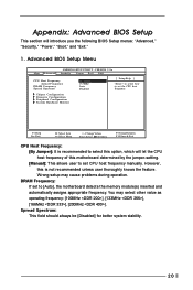
...Frequency: If set to set CPU host frequency manually. Appendix: Advanced BIOS Setup This section will let the CPU host frequency of this motherboard determined by the jumper-setting. [Manual]: This allows user to set the CPU host frequency. Wrong setup may select other value as... Actual Frequency DRAM Frequency Spread Spectrum By Jumper 133MHz Auto Disabled [ Setup Help ] to select how to [Auto], the motherboard detects the memory module(s) inserted and automatically assigns appropriate frequency. Spread Spectrum: This field should always be [Disabled] for better system stability....
...Frequency: If set to set CPU host frequency manually. Appendix: Advanced BIOS Setup This section will let the CPU host frequency of this motherboard determined by the jumper-setting. [Manual]: This allows user to set the CPU host frequency. Wrong setup may select other value as... Actual Frequency DRAM Frequency Spread Spectrum By Jumper 133MHz Auto Disabled [ Setup Help ] to select how to [Auto], the motherboard detects the memory module(s) inserted and automatically assigns appropriate frequency. Spread Spectrum: This field should always be [Disabled] for better system stability....
User Manual
Page 23
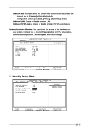
... Supervisor Password User Password Set Supervisor Password Set User Password Clear Clear [ Enter ] [ Enter ] [ Setup Help ] to set to monitor the parameters for CPU temperature, Motherboard temperature, CPU fan speed, and critical voltage. VERSION 3.31a System Hardware Monitor [ Setup Help ] CPU Temperature M / B Temperature CPU FAN Speed Chassis FAN Speed Vcore + 3.30V...
... Supervisor Password User Password Set Supervisor Password Set User Password Clear Clear [ Enter ] [ Enter ] [ Setup Help ] to set to monitor the parameters for CPU temperature, Motherboard temperature, CPU fan speed, and critical voltage. VERSION 3.31a System Hardware Monitor [ Setup Help ] CPU Temperature M / B Temperature CPU FAN Speed Chassis FAN Speed Vcore + 3.30V...

