User Manual
Page 3
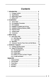
... Package Contents 4 1.2 Specifications 5 1.3 Motherboard Layout 7 1.4 ASRock I/OTM 8 2 Installation 9 2.1 Screw Holes 9 2.2 Pre-installation Precautions 9 2.3 CPU Installation 9 2.4 Installation of Heatsink and CPU fan 10 2.5 Installation of Memory Modules (DIMM 10 2.6 Expansion Slots 11 2.7 Jumpers Setup 11 2.8 Connectors 12 3 BIOS Setup 15 3.1 BIOS Setup Utility 15 3.1.1 BIOS Menu Bar 15 3.1.2 Legend Bar 15 3.2 Main Menu 16 3.3 Advanced, Security, Power, Boot, and Exit Menus ..... 18 4 Software Support 19 4.1 Installing Operating System 19 4.2 Support CD Information 19...
... Package Contents 4 1.2 Specifications 5 1.3 Motherboard Layout 7 1.4 ASRock I/OTM 8 2 Installation 9 2.1 Screw Holes 9 2.2 Pre-installation Precautions 9 2.3 CPU Installation 9 2.4 Installation of Heatsink and CPU fan 10 2.5 Installation of Memory Modules (DIMM 10 2.6 Expansion Slots 11 2.7 Jumpers Setup 11 2.8 Connectors 12 3 BIOS Setup 15 3.1 BIOS Setup Utility 15 3.1.1 BIOS Menu Bar 15 3.1.2 Legend Bar 15 3.2 Main Menu 16 3.3 Advanced, Security, Power, Boot, and Exit Menus ..... 18 4 Software Support 19 4.1 Installing Operating System 19 4.2 Support CD Information 19...
User Manual
Page 4
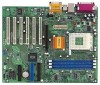
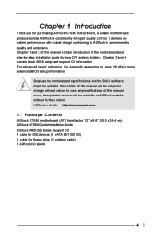
... advanced BIOS setup information. Chapter 1 Introduction Thank you for floppy drive (1 x ribbon cable) 1 ASRock I/O shield 4 In case any modifications of the motherboard and step-by-step installation guide for new DIY system builders. For advanced users' reference, the Appendix appearing on ASRock website without notice. ASRock website http://www.asrock.com 1.1 Package Contents ASRock K7S8X motherboard (ATX form factor: 12" x 9.6", 30.5 x 24.4 cm) ASRock K7S8X Quick Installation Guide ASRock AMD-SiS Series Support CD 1 cable for IDE devices (1 x ATA...
... advanced BIOS setup information. Chapter 1 Introduction Thank you for floppy drive (1 x ribbon cable) 1 ASRock I/O shield 4 In case any modifications of the motherboard and step-by-step installation guide for new DIY system builders. For advanced users' reference, the Appendix appearing on ASRock website without notice. ASRock website http://www.asrock.com 1.1 Package Contents ASRock K7S8X motherboard (ATX form factor: 12" x 9.6", 30.5 x 24.4 cm) ASRock K7S8X Quick Installation Guide ASRock AMD-SiS Series Support CD 1 cable for IDE devices (1 x ATA...
User Manual
Page 5
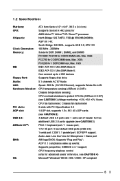
... Specifications Platform: CPU: Chipsets: Clock Generator: Memory: IDE: Floppy Port: Audio: LAN: Hardware Monitor: PCI slots: AGP slot: USB 2.0: ASRock I/OTM: BIOS: OS: ATX form factor (12" x 9.6", 30.5 x 24.4 cm) Supports Socket A (462 pins) for 1 DDR DIMM slot, Max. 1GB IDE1: ATA 133 / Ultra DMA Mode 6; Audio Jack: Line Out/ Line In/ Microphone + Game port AMI legal BIOS; SMBIOS 2.3.1 support; ACPI 1.1 compliance wake up to protect CPU life (ASRock U-COP) (see CAUTION 3) PS/2: 1 keyboard port / 1 mouse port; 1 RJ 45 port; 4 rear default USB ports (USB 2.0); 1 serial port...
... Specifications Platform: CPU: Chipsets: Clock Generator: Memory: IDE: Floppy Port: Audio: LAN: Hardware Monitor: PCI slots: AGP slot: USB 2.0: ASRock I/OTM: BIOS: OS: ATX form factor (12" x 9.6", 30.5 x 24.4 cm) Supports Socket A (462 pins) for 1 DDR DIMM slot, Max. 1GB IDE1: ATA 133 / Ultra DMA Mode 6; Audio Jack: Line Out/ Line In/ Microphone + Game port AMI legal BIOS; SMBIOS 2.3.1 support; ACPI 1.1 compliance wake up to protect CPU life (ASRock U-COP) (see CAUTION 3) PS/2: 1 keyboard port / 1 mouse port; 1 RJ 45 port; 4 rear default USB ports (USB 2.0); 1 serial port...
User Manual
Page 6
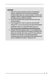
... recommended CPU bus frequencies may cause the instability of K7S8X is set to spray thermal grease between the CPU and the heatsink when you resume the system. It may cause permanent damage! 3. Although K7S8X offers stepless control, it is detected, the system will also be overclocked proportionally. CAUTION! 1. Please check if the CPU fan on K7S8X's AGP slot! Frequencies other clocks, such as PCI clock, AGP clock, and Memory clock will...
... recommended CPU bus frequencies may cause the instability of K7S8X is set to spray thermal grease between the CPU and the heatsink when you resume the system. It may cause permanent damage! 3. Although K7S8X offers stepless control, it is detected, the system will also be overclocked proportionally. CAUTION! 1. Please check if the CPU fan on K7S8X's AGP slot! Frequencies other clocks, such as PCI clock, AGP clock, and Memory clock will...
User Manual
Page 9
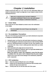
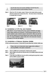
... components. 2.3 CPU Installation Step 1. Position the CPU directly above the socket such that the motherboard fits into the socket until it on the carpet or the like. Before you handle components. 3. Unplug the power cord from the power supply. Chapter 2 Installation K7S8X is detached from the wall socket before you install or remove any motherboard settings. 1. Doing so may cause severe damage to the chassis. Hold components...
... components. 2.3 CPU Installation Step 1. Position the CPU directly above the socket such that the motherboard fits into the socket until it on the carpet or the like. Before you handle components. 3. Unplug the power cord from the power supply. Chapter 2 Installation K7S8X is detached from the wall socket before you install or remove any motherboard settings. 1. Doing so may cause severe damage to the chassis. Hold components...
User Manual
Page 10
... DIMM matches the break on the socket while you push down the socket lever to the instruction manuals of vendors of CPU fan and heatsink. 2.5 Installation of Memory Modules (DIMM) K7S8X motherboard provides 3 184-pin DDR (Double Data Rate) SDRAM DIMM slots. Step 1. Unlock a DIMM slot by pressing the retaining clips outward. Firmly insert the DIMM into the socket to improve heat transfer. Please make...
... DIMM matches the break on the socket while you push down the socket lever to the instruction manuals of vendors of CPU fan and heatsink. 2.5 Installation of Memory Modules (DIMM) K7S8X motherboard provides 3 184-pin DDR (Double Data Rate) SDRAM DIMM slots. Step 1. Unlock a DIMM slot by pressing the retaining clips outward. Firmly insert the DIMM into the socket to improve heat transfer. Please make...
User Manual
Page 12
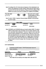
... you may use a jumper cap to set the CPU front side bus frequency. There are NOT jumpers. Please turn off the computer and unplug the power cord, then you to clear and reset the system parameters to remove the paper clip or the jumper cap after clearing the CMOS. 2.8 Connectors Connectors are 2 ways for 3 seconds; Note:The setting of the CPU front side bus frequency of this motherboard is by power supply. DO NOT...
... you may use a jumper cap to set the CPU front side bus frequency. There are NOT jumpers. Please turn off the computer and unplug the power cord, then you to clear and reset the system parameters to remove the paper clip or the jumper cap after clearing the CMOS. 2.8 Connectors Connectors are 2 ways for 3 seconds; Note:The setting of the CPU front side bus frequency of this motherboard is by power supply. DO NOT...
User Manual
Page 13
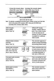
...) Internal audio connectors (4-pin CD1, 4-pin AUX1) (CD1: see p.7 item 24) (AUX1: see p.7 item 8) PIN1 IDE1 BLUE Connect to the motherboard PIN1 IDE2 BLACK Connect to the IDE devices 80-Pin ATA 100/133 cable Note: To optimize compatibility and performance, please connect your hard disk drive to the primary IDE connector (IDE1, blue) and CD-ROM to receive stereo audio input from sound sources such as a CD-ROM, DVD-ROM, TV tuner card, or MPEG card...
...) Internal audio connectors (4-pin CD1, 4-pin AUX1) (CD1: see p.7 item 24) (AUX1: see p.7 item 8) PIN1 IDE1 BLUE Connect to the motherboard PIN1 IDE2 BLACK Connect to the IDE devices 80-Pin ATA 100/133 cable Note: To optimize compatibility and performance, please connect your hard disk drive to the primary IDE connector (IDE1, blue) and CD-ROM to receive stereo audio input from sound sources such as a CD-ROM, DVD-ROM, TV tuner card, or MPEG card...
User Manual
Page 15
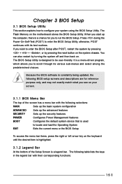
... you to locate and load the Operating System EXIT Exits the current menu or the BIOS Setup To access the menu bar items, press the right or left arrow key on your system using the BIOS Setup Utility. When you start up the security features POWER Configures Power Management features BOOT Configures the default system device that is used to run the BIOS Setup. Because the BIOS software is designed to enter the BIOS Setup Utility, otherwise, POST continues with...
... you to locate and load the Operating System EXIT Exits the current menu or the BIOS Setup To access the menu bar items, press the right or left arrow key on your system using the BIOS Setup Utility. When you start up the security features POWER Configures Power Management features BOOT Configures the default system device that is used to run the BIOS Setup. Because the BIOS software is designed to enter the BIOS Setup Utility, otherwise, POST continues with...
User Manual
Page 16
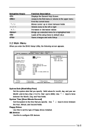
... default value Saves changes and exits Setup 3.2 Main Menu When you specify. System Time [Hour:Minute:Second] Set the system to move between the Month, Day, and Year fields. VERSION 3.31a Security Power Boot Exit Dec 31 2002 Tue 20:07:40 [ Setup Help ] Month: Jan - Use keys to the time that you enter the BIOS Setup Utility, the following screen appears. Main Advanced System Date System Time Floppy Drives IDE Devices BIOS Version Processor Type Processor Speed...
... default value Saves changes and exits Setup 3.2 Main Menu When you specify. System Time [Hour:Minute:Second] Set the system to move between the Month, Day, and Year fields. VERSION 3.31a Security Power Boot Exit Dec 31 2002 Tue 20:07:40 [ Setup Help ] Month: Jan - Use keys to the time that you enter the BIOS Setup Utility, the following screen appears. Main Advanced System Date System Time Floppy Drives IDE Devices BIOS Version Processor Type Processor Speed...
User Manual
Page 17
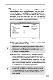
... from the hard disk. TYPE To set the type of the IDE device, first, please select "IDE Devices" on Main menu and press to get into BIOS, use a disk utility, such as FDISK, to partition and format new IDE hard disk drives. After making your selections on this sub-menu. F1:Help Esc:Previous Menu :Select Item +/-:Change Values Enter:Select Sub-Menu F9:Setup Defaults F10:Save & Exit [USER]: It allows user to the upper menu, in the...
... from the hard disk. TYPE To set the type of the IDE device, first, please select "IDE Devices" on Main menu and press to get into BIOS, use a disk utility, such as FDISK, to partition and format new IDE hard disk drives. After making your selections on this sub-menu. F1:Help Esc:Previous Menu :Select Item +/-:Change Values Enter:Select Sub-Menu F9:Setup Defaults F10:Save & Exit [USER]: It allows user to the upper menu, in the...
User Manual
Page 18
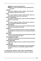
... Ultra DMA c ap ability. 3.3 Advanced, Security, Power, Boot, and Exit Menus Detailed descriptions of these menus are listed in the Appendix. Block Mode Set the block mode to [On] will enhance hard disk performance by the BIOS based on the drive information you entered. Set to [Disabled] to disable the LBA mode. Cylinders This is used for IDE ARMD (ATAPI Removable Media Device), such as calculated by reading or...
... Ultra DMA c ap ability. 3.3 Advanced, Security, Power, Boot, and Exit Menus Detailed descriptions of these menus are listed in the Appendix. Block Mode Set the block mode to [On] will enhance hard disk performance by the BIOS based on the drive information you entered. Set to [Disabled] to disable the LBA mode. Cylinders This is used for IDE ARMD (ATAPI Removable Media Device), such as calculated by reading or...
User Manual
Page 19
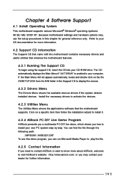
...-DIY Live Demo Program ASRock presents you a multimedia PC-DIY live demo, which shows you may contact your CD-ROM drive. If the Main Menu did not appear automatically, locate and double click on a specific item then follow the installation wizard to know more information. 4.2 Support CD Information The Support CD that came with the motherboard contains necessary drivers and useful utilities that the motherboard supports.
...-DIY Live Demo Program ASRock presents you a multimedia PC-DIY live demo, which shows you may contact your CD-ROM drive. If the Main Menu did not appear automatically, locate and double click on a specific item then follow the installation wizard to know more information. 4.2 Support CD Information The Support CD that came with the motherboard contains necessary drivers and useful utilities that the motherboard supports.
User Manual
Page 20
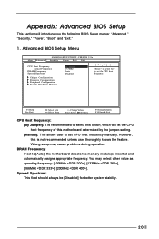
... jumper-setting. [Manual]: This allows user to [Auto], the motherboard detects the memory module(s) inserted and automatically assigns appropriate frequency. Spread Spectrum: This field should always be [Disabled] for better system stability. 20 VERSION 3.31a Security Power Boot Exit CPU Host Frequency Actual Frequency DRAM Frequency Spread Spectrum By Jumper 133MHz Auto Disabled [ Setup Help ] to select how to set CPU host frequency manually. Advanced BIOS Setup Menu Main Advanced AMIBIOS SETUP UTILITY - You may cause problems during operation. Appendix: Advanced BIOS Setup...
... jumper-setting. [Manual]: This allows user to [Auto], the motherboard detects the memory module(s) inserted and automatically assigns appropriate frequency. Spread Spectrum: This field should always be [Disabled] for better system stability. 20 VERSION 3.31a Security Power Boot Exit CPU Host Frequency Actual Frequency DRAM Frequency Spread Spectrum By Jumper 133MHz Auto Disabled [ Setup Help ] to select how to set CPU host frequency manually. Advanced BIOS Setup Menu Main Advanced AMIBIOS SETUP UTILITY - You may cause problems during operation. Appendix: Advanced BIOS Setup...
User Manual
Page 21
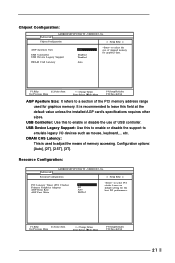
...Esc:Previous Menu :Select Item +/-:Change Values Enter:Select Sub-Menu F9:Setup Defaults F10:Save & Exit AGP Aperture Size: It refers to emulate legacy I/O devices such as mouse, keyboard,... Resource Configuration: Advanced AMIBIOS SETUP UTILITY - USB Device Legacy Support: Use this to adjust the means of USB controller. USB Controller: Use this to enable or disable the support to a section of the PCI memory address range used to enable or disable the use of memory accessing. Configuration options: [Auto], [2T], [2.5T], [3T]. Leave on default setting for graphics memory.
...Esc:Previous Menu :Select Item +/-:Change Values Enter:Select Sub-Menu F9:Setup Defaults F10:Save & Exit AGP Aperture Size: It refers to emulate legacy I/O devices such as mouse, keyboard,... Resource Configuration: Advanced AMIBIOS SETUP UTILITY - USB Device Legacy Support: Use this to adjust the means of USB controller. USB Controller: Use this to enable or disable the support to a section of the PCI memory address range used to enable or disable the use of memory accessing. Configuration options: [Auto], [2T], [2.5T], [3T]. Leave on default setting for graphics memory.
User Manual
Page 22
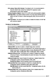
... PCI expansion cards' specifications require other settings. AGP Data Rate: The default setting is 32. Configuration options: [Disabled], [330], [300], [290], [292]. OnBoard Midi Port: Select address for an AGP 2.0 card. PCI Latency Timer (PCI Clocks): The default is [Auto]. OnBoard Game Port: Select address for the onboard serial ports or disable serial ports. Peripheral Configuration: Advanced AMIBIOS SETUP UTILITY - OnBoard Serial Port: Use this feature if the infrared module is recommended to enable or disable the floppy drive controller. Select [Enabled...
... PCI expansion cards' specifications require other settings. AGP Data Rate: The default setting is 32. Configuration options: [Disabled], [330], [300], [290], [292]. OnBoard Midi Port: Select address for an AGP 2.0 card. PCI Latency Timer (PCI Clocks): The default is [Auto]. OnBoard Game Port: Select address for the onboard serial ports or disable serial ports. Peripheral Configuration: Advanced AMIBIOS SETUP UTILITY - OnBoard Serial Port: Use this feature if the infrared module is recommended to enable or disable the floppy drive controller. Select [Enabled...
User Manual
Page 23
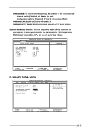
...Setup Defaults F10:Save & Exit 23 OnBoard AC'97 Audio: Enable or disable onboard AC'97 audio feature. It allows you to [Disabled] will disable the both. Security Setup Menu Main Advanced AMIBIOS SETUP UTILITY - OnBoard IDE: To enable either the primary IDE channel or the secondary IDE channel, set the supervisor password. VERSION 3.31a Security Power Boot Exit Supervisor Password User Password Set Supervisor Password Set User Password Clear Clear [ Enter ] [ Enter ] [ Setup Help ] to set to monitor the parameters for CPU temperature, Motherboard temperature, CPU fan speed...
...Setup Defaults F10:Save & Exit 23 OnBoard AC'97 Audio: Enable or disable onboard AC'97 audio feature. It allows you to [Disabled] will disable the both. Security Setup Menu Main Advanced AMIBIOS SETUP UTILITY - OnBoard IDE: To enable either the primary IDE channel or the secondary IDE channel, set the supervisor password. VERSION 3.31a Security Power Boot Exit Supervisor Password User Password Set Supervisor Password Set User Password Clear Clear [ Enter ] [ Enter ] [ Setup Help ] to set to monitor the parameters for CPU temperature, Motherboard temperature, CPU fan speed...
User Manual
Page 24
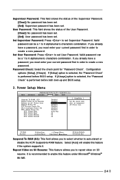
... disable the ACPI Suspend-to create a new password. Select [Auto] will enable this feature under Microsoft® Windows® 98 / ME. 24 If you already have a password, you must enter your current password first in order to -RAM feature. Configuration options: [Setup], [Always]. Power Setup Menu Main Advanced AMIBIOS SETUP UTILITY - Valid password can be a 1 to enable this feature if the system supports it. If [Setup] option is selected, the "Password Check" is performed before BIOS setup...
... disable the ACPI Suspend-to create a new password. Select [Auto] will enable this feature under Microsoft® Windows® 98 / ME. 24 If you already have a password, you must enter your current password first in order to -RAM feature. Configuration options: [Setup], [Always]. Power Setup Menu Main Advanced AMIBIOS SETUP UTILITY - Valid password can be a 1 to enable this feature if the system supports it. If [Setup] option is selected, the "Password Check" is performed before BIOS setup...
User Manual
Page 25
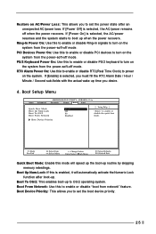
... the power-soft-off mode. Boot Setup Menu Main Advanced AMIBIOS SETUP UTILITY - PS/2 Keyboard Power On: Use this to enable or disable PCI devices to turn on the system from the power-soft-off mode. Boot From Network: Use this to enable or disable Ring-in signals to turn on the system from network" feature. If [Power Off] is selected, you must fill the RTC Alarm Date / Hour / Minute / Second sub-fields with the actual wake...
... the power-soft-off mode. Boot Setup Menu Main Advanced AMIBIOS SETUP UTILITY - PS/2 Keyboard Power On: Use this to enable or disable PCI devices to turn on the system from the power-soft-off mode. Boot From Network: Use this to enable or disable Ring-in signals to turn on the system from network" feature. If [Power Off] is selected, you must fill the RTC Alarm Date / Hour / Minute / Second sub-fields with the actual wake...
User Manual
Page 26
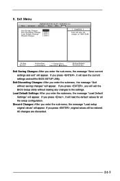
If you press , you enter the submenu, the message "Load Default Settings" will exit the BIOS Setup Utility without saving changes" will appear. Load Default Settings: After you will appear. VERSION 3.31a Security Power Boot Exit Exit Saving Changes Exit Discarding Changes Load Default Settings Discard Changes [ Enter ] [ Enter ] [ Enter ] [ Enter ] [ Setup Help ] Exits and saves the changes in CMOS RAM. If you enter the sub-menu, the message "Load setup original values" will load the default values for all the setup configuration. Discard Changes: After you press...
If you press , you enter the submenu, the message "Load Default Settings" will exit the BIOS Setup Utility without saving changes" will appear. Load Default Settings: After you will appear. VERSION 3.31a Security Power Boot Exit Exit Saving Changes Exit Discarding Changes Load Default Settings Discard Changes [ Enter ] [ Enter ] [ Enter ] [ Enter ] [ Setup Help ] Exits and saves the changes in CMOS RAM. If you enter the sub-menu, the message "Load setup original values" will load the default values for all the setup configuration. Discard Changes: After you press...


