User Manual
Page 3
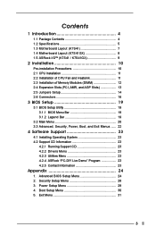
... Introduction 4 1.1 Package Contents 4 1.2 Specifications 5 1.3 Motherboard Layout (K7S41 7 1.4 Motherboard Layout (K7S41GX 8 1.5 ASRock I/OTM (K7S41 / K7S41GX 9 2 Installation 10 Pre-installation Precautions 10 2.1 CPU Installation 11 2.2 Installation of CPU Fan and Heatsink 11 2.3 Installation of Memory Modules (DIMM 12 2.4..., Boot, and Exit Menus ...... 22 4 Software Support 23 4.1 Installing Operating System 23 4.2 Support CD Information 23 4.2.1 Running Support CD 23 4.2.2 Drivers Menu 23 4.2.3 Utilities Menu 23 4.2.4 ASRock "PC-DIY Live Demo" Program 23 4.2.5 Contact ...
... Introduction 4 1.1 Package Contents 4 1.2 Specifications 5 1.3 Motherboard Layout (K7S41 7 1.4 Motherboard Layout (K7S41GX 8 1.5 ASRock I/OTM (K7S41 / K7S41GX 9 2 Installation 10 Pre-installation Precautions 10 2.1 CPU Installation 11 2.2 Installation of CPU Fan and Heatsink 11 2.3 Installation of Memory Modules (DIMM 12 2.4..., Boot, and Exit Menus ...... 22 4 Software Support 23 4.1 Installing Operating System 23 4.2 Support CD Information 23 4.2.1 Running Support CD 23 4.2.2 Drivers Menu 23 4.2.3 Utilities Menu 23 4.2.4 ASRock "PC-DIY Live Demo" Program 23 4.2.5 Contact ...

User Manual
Page 4
Chapter 3 and 4 contain basic BIOS setup and support CD information. You may find the latest memory and CPU support lists on page 24 for a 3.5-in , 24.4 cm x 19.8 cm) ASRock K7S41 / K7S41GX Quick Installation Guide ASRock K7S41 / K7S41GX Support CD One 80-conductor Ultra ATA 66/100/133 IDE Ribbon Cable One Ribbon Cable for advanced users' reference. Because...
Chapter 3 and 4 contain basic BIOS setup and support CD information. You may find the latest memory and CPU support lists on page 24 for a 3.5-in , 24.4 cm x 19.8 cm) ASRock K7S41 / K7S41GX Quick Installation Guide ASRock K7S41 / K7S41GX Support CD One 80-conductor Ultra ATA 66/100/133 IDE Ribbon Cable One Ribbon Cable for advanced users' reference. Because...

User Manual
Page 6
BIOS: OS: AMI legal BIOS, "Plug and Play" support, ACPI 1.1 compliance wake up events, SMBIOS 2.3.1 support, CPU frequency stepless control (only for details. 6 Do NOT use the "Manual" option as the FSB setting in BIOS setup to Microsoft® official ...document at http://www.microsoft.com/whdc/hwdev/bus/USB/USB2support.mspx 4. Please refer to perform over clocking. While CPU overheat is determined by...
BIOS: OS: AMI legal BIOS, "Plug and Play" support, ACPI 1.1 compliance wake up events, SMBIOS 2.3.1 support, CPU frequency stepless control (only for details. 6 Do NOT use the "Manual" option as the FSB setting in BIOS setup to Microsoft® official ...document at http://www.microsoft.com/whdc/hwdev/bus/USB/USB2support.mspx 4. Please refer to perform over clocking. While CPU overheat is determined by...

User Manual
Page 11
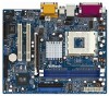
... motherboard adopts 462-pin CPU socket to improve heat dissipation. The CPU fits only in good contact with each other. When the CPU is locked. You also need to spray thermal grease between the CPU and the heatsink to support AMD Athlon XP / Duron CPU. For proper installation, ...please kindly refer to a 90o angle. 2.1 Step 1. CPU Installation Unlock the socket by lifting the...
... motherboard adopts 462-pin CPU socket to improve heat dissipation. The CPU fits only in good contact with each other. When the CPU is locked. You also need to spray thermal grease between the CPU and the heatsink to support AMD Athlon XP / Duron CPU. For proper installation, ...please kindly refer to a 90o angle. 2.1 Step 1. CPU Installation Unlock the socket by lifting the...
User Manual
Page 16
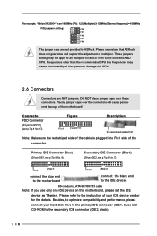
... 1 FID0 FID1 FID2 FID3 FID4 The jumper caps are NOT jumpers. Please understand that ASRock does not guarantee and support the adjustment of the system or damage the CPU. 2.6 Connectors Connectors are not provided by ASRock. Connector FDD Connector (33-pin FLOPPY1) (see p.7/p.8 No. 7) PIN1 IDE1 PIN1 ... Please refer to the instruction of the connector. Frequencies other than the recommended CPU bus frequencies may not apply to all multiplier-locked or even some unlocked AMD CPU. These jumpers setting may cause the instability of multiplier. Besides, to optimize ...
... 1 FID0 FID1 FID2 FID3 FID4 The jumper caps are NOT jumpers. Please understand that ASRock does not guarantee and support the adjustment of the system or damage the CPU. 2.6 Connectors Connectors are not provided by ASRock. Connector FDD Connector (33-pin FLOPPY1) (see p.7/p.8 No. 7) PIN1 IDE1 PIN1 ... Please refer to the instruction of the connector. Frequencies other than the recommended CPU bus frequencies may not apply to all multiplier-locked or even some unlocked AMD CPU. These jumpers setting may cause the instability of multiplier. Besides, to optimize ...

User Manual
Page 17
.... 29) AUX-L GND GND AUX1 AUX-R CD-L GND GND CD1 CD-R These connectors allow you to support 2 additional USB 2.0 ports. CPU Fan Connector (3-pin CPU_FAN1) (see p.7/p.8 No. 19) IRTX +5V DUMMY 1 GND IRRX This connector supports an optional wireless transmitting and receiving infrared module. R MIC-POWER MIC This is available to receive stereo... Please connect the chassis speaker to this connector and match the black wire to this connector. Infrared Module Connector (5-pin IR1) (see p.7/p.8 No. 2) Please connect a CPU fan cable to the ground pin. 17 O U T-
.... 29) AUX-L GND GND AUX1 AUX-R CD-L GND GND CD1 CD-R These connectors allow you to support 2 additional USB 2.0 ports. CPU Fan Connector (3-pin CPU_FAN1) (see p.7/p.8 No. 19) IRTX +5V DUMMY 1 GND IRRX This connector supports an optional wireless transmitting and receiving infrared module. R MIC-POWER MIC This is available to receive stereo... Please connect the chassis speaker to this connector and match the black wire to this connector. Infrared Module Connector (5-pin IR1) (see p.7/p.8 No. 2) Please connect a CPU fan cable to the ground pin. 17 O U T-

User Manual
Page 25
...Help ] Onboard VGA Share Memory AGP Aperture Size USB Controller USB 2.0 Controller USB Device Legacy Support DRAM CAS Latency Over Vcore Voltage Auto 64M Enabled Enabled Disabled Auto Disabled to increase the CPU Vcore voltage by 3% or 6%. It is selected. The default value is used for onboard ... memory accessing. Over Vcore Voltage: This feature allows you to leave this to enable or disable the support to adjust the means of USB controller. Doing so may cause CPU damage. 25 Chipset Configuration: Advanced AMIBIOS SETUP UTILITY - It is set the share memory size of...
...Help ] Onboard VGA Share Memory AGP Aperture Size USB Controller USB 2.0 Controller USB Device Legacy Support DRAM CAS Latency Over Vcore Voltage Auto 64M Enabled Enabled Disabled Auto Disabled to increase the CPU Vcore voltage by 3% or 6%. It is selected. The default value is used for onboard ... memory accessing. Over Vcore Voltage: This feature allows you to leave this to enable or disable the support to adjust the means of USB controller. Doing so may cause CPU damage. 25 Chipset Configuration: Advanced AMIBIOS SETUP UTILITY - It is set the share memory size of...


