User Manual
Page 3
...1.2 Specifications 5 1.3 Motherboard Layout (K7S41 7 1.4 Motherboard Layout (K7S41GX 8 1.5 ASRock I/OTM (K7S41 / K7S41GX 9 2 Installation 10 Pre-installation Precautions 10 2.1 CPU Installation 11 2.2 Installation of CPU Fan and Heatsink 11 2.3 Installation of Memory Modules (DIMM 12 2.4 Expansion Slots (PCI, AMR, and AGP Slots 13 2.5 Jumpers Setup 14 2.6 Connectors 16 3 BIOS Setup 19 3.1 BIOS Setup Utility 19 3.1.1 BIOS Menu Bar 19 3.1.2 Legend Bar 19 3.2 Main Menu 20 3.3 Advanced, Security, Power, Boot, and Exit Menus ...... 22 4 Software Support 23 4.1 Installing Operating...
...1.2 Specifications 5 1.3 Motherboard Layout (K7S41 7 1.4 Motherboard Layout (K7S41GX 8 1.5 ASRock I/OTM (K7S41 / K7S41GX 9 2 Installation 10 Pre-installation Precautions 10 2.1 CPU Installation 11 2.2 Installation of CPU Fan and Heatsink 11 2.3 Installation of Memory Modules (DIMM 12 2.4 Expansion Slots (PCI, AMR, and AGP Slots 13 2.5 Jumpers Setup 14 2.6 Connectors 16 3 BIOS Setup 19 3.1 BIOS Setup Utility 19 3.1.1 BIOS Menu Bar 19 3.1.2 Legend Bar 19 3.2 Main Menu 20 3.3 Advanced, Security, Power, Boot, and Exit Menus ...... 22 4 Software Support 23 4.1 Installing Operating...

User Manual
Page 4
... Floppy Drive One ASRock I/OTM Shield One COM Port Bracket One ASRock MR Card (Optional) 4 Because the motherboard specifications and the BIOS software might be updated, the content of advanced BIOS setup is offered on ASRock website as well. Chapter 1 and 2 of the motherboard and step-bystep installation guide. It delivers excellent performance with robust design conforming to ASRock's commitment to change without further notice. You may find the latest memory...
... Floppy Drive One ASRock I/OTM Shield One COM Port Bracket One ASRock MR Card (Optional) 4 Because the motherboard specifications and the BIOS software might be updated, the content of advanced BIOS setup is offered on ASRock website as well. Chapter 1 and 2 of the motherboard and step-bystep installation guide. It delivers excellent performance with robust design conforming to ASRock's commitment to change without further notice. You may find the latest memory...

User Manual
Page 6
... automatically shutdown. Frequencies other than the recommended CPU bus frequencies may cause permanent damage! 3. Power Management for USB 2.0 works fine under Microsoft® Windows® 98/ME. Although this motherboard is determined by the jumper-setting. BIOS: OS: AMI legal BIOS, "Plug and Play" support, ACPI 1.1 compliance wake up events, SMBIOS 2.3.1 support, CPU frequency stepless control (only for details. 6 Please refer to your AMD CPU before you install the PC system. 2. While CPU overheat is...
... automatically shutdown. Frequencies other than the recommended CPU bus frequencies may cause permanent damage! 3. Power Management for USB 2.0 works fine under Microsoft® Windows® 98/ME. Although this motherboard is determined by the jumper-setting. BIOS: OS: AMI legal BIOS, "Plug and Play" support, ACPI 1.1 compliance wake up events, SMBIOS 2.3.1 support, CPU frequency stepless control (only for details. 6 Please refer to your AMD CPU before you install the PC system. 2. While CPU overheat is...
User Manual
Page 7
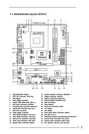
...6 ATX Power Connector (ATXPWR1) 7 Secondary IDE Connector (IDE2, Black) 8 Primary IDE Connector (IDE1, Blue) 9 AGP Slot (1.5V_AGP1) 10 South Bridge Controller 11 Clear CMOS (CLRCMOS1, solder points) 12 Clear CMOS (CLRCMOS2, 2-pin jumper) 13 Chassis Fan Connector (CHA_FAN1) 14 Power LED Connector (PWR_LED1) 15 System Panel Connector (PANEL1) 16 Chassis Speaker Connector (SPEAKER 1) 17 Floppy Connector (FLOPPY1) 18 USB 2.0 Connector (USB45, Blue) 19 Infrared Module Connector (IR1) 20 AMR Slot (AMR1) 21 Flash Memory 22 Serial Port Connector (COM1) 23 JL1 Jumper 24 JR1 Jumper 25 Front Panel Audio...
...6 ATX Power Connector (ATXPWR1) 7 Secondary IDE Connector (IDE2, Black) 8 Primary IDE Connector (IDE1, Blue) 9 AGP Slot (1.5V_AGP1) 10 South Bridge Controller 11 Clear CMOS (CLRCMOS1, solder points) 12 Clear CMOS (CLRCMOS2, 2-pin jumper) 13 Chassis Fan Connector (CHA_FAN1) 14 Power LED Connector (PWR_LED1) 15 System Panel Connector (PANEL1) 16 Chassis Speaker Connector (SPEAKER 1) 17 Floppy Connector (FLOPPY1) 18 USB 2.0 Connector (USB45, Blue) 19 Infrared Module Connector (IR1) 20 AMR Slot (AMR1) 21 Flash Memory 22 Serial Port Connector (COM1) 23 JL1 Jumper 24 JR1 Jumper 25 Front Panel Audio...
User Manual
Page 8
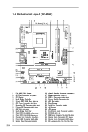
...ATX Power Connector (ATXPWR1) 7 Secondary IDE Connector (IDE2, Black) 8 Primary IDE Connector (IDE1, Blue) 9 AGP Slot (1.5V_AGP1) 10 South Bridge Controller 11 Clear CMOS (CLRCMOS1, solder points) 12 Clear CMOS (CLRCMOS2, 2-pin jumper) 13 Chassis Fan Connector (CHA_FAN1) 14 Power LED Connector (PWR_LED1) 15 System Panel Connector (PANEL1) 8 16 Chassis Speaker Connector (SPEAKER 1) 17 Floppy Connector (FLOPPY1) 18 USB 2.0 Connector (USB45, Blue) 19 Infrared Module Connector (IR1) 20 AMR Slot (AMR1) 21 Flash Memory 22 Serial Port Connector (COM1) 23 JL1 Jumper 24 JR1 Jumper 25 Front Panel Audio...
...ATX Power Connector (ATXPWR1) 7 Secondary IDE Connector (IDE2, Black) 8 Primary IDE Connector (IDE1, Blue) 9 AGP Slot (1.5V_AGP1) 10 South Bridge Controller 11 Clear CMOS (CLRCMOS1, solder points) 12 Clear CMOS (CLRCMOS2, 2-pin jumper) 13 Chassis Fan Connector (CHA_FAN1) 14 Power LED Connector (PWR_LED1) 15 System Panel Connector (PANEL1) 8 16 Chassis Speaker Connector (SPEAKER 1) 17 Floppy Connector (FLOPPY1) 18 USB 2.0 Connector (USB45, Blue) 19 Infrared Module Connector (IR1) 20 AMR Slot (AMR1) 21 Flash Memory 22 Serial Port Connector (COM1) 23 JL1 Jumper 24 JR1 Jumper 25 Front Panel Audio...

User Manual
Page 13
.... Replace the system cover. 13 2.4 Expansion Slots (PCI, AMR, and AGP Slots) There are used to the chassis with screws. The ASRock AGP slot has a special design of your motherboard is used to install a graphics card. Installing an expansion card Step 1. Remove the bracket facing the slot that have the 32-bit PCI interface. Fasten the card to install expansion cards that you start the installation. For the voltage information of clasp that the power supply is switched...
.... Replace the system cover. 13 2.4 Expansion Slots (PCI, AMR, and AGP Slots) There are used to the chassis with screws. The ASRock AGP slot has a special design of your motherboard is used to install a graphics card. Installing an expansion card Step 1. Remove the bracket facing the slot that have the 32-bit PCI interface. Fasten the card to install expansion cards that you start the installation. For the voltage information of clasp that the power supply is switched...

User Manual
Page 14
... panel and rear panel audio connectors can work. 14 PS2_USB_PWR1 1_2 2_3 Short pin2, pin3 to set the FSB jumper according to your AMD CPU before you use the "Manual" option as the FSB setting in BIOS setup to perform over clocking. The illustration shows a 3-pin jumper whose pin1 and pin2 are "SHORT" when jumper cap is "OPEN". You must set the CPU front side bus frequency. If no jumper cap is placed on the pins, the jumper...
... panel and rear panel audio connectors can work. 14 PS2_USB_PWR1 1_2 2_3 Short pin2, pin3 to set the FSB jumper according to your AMD CPU before you use the "Manual" option as the FSB setting in BIOS setup to perform over clocking. The illustration shows a 3-pin jumper whose pin1 and pin2 are "SHORT" when jumper cap is "OPEN". You must set the CPU front side bus frequency. If no jumper cap is placed on the pins, the jumper...

User Manual
Page 19
Chapter 3 BIOS Setup 3.1 BIOS Setup Utility This section explains how to use the BIOS Setup Utility to enter the BIOS Setup after POST, restart the system by pressing + + , or by turning the system off and then back on the motherboard stores the BIOS Setup Utility. The Flash Memory on . If you start up the security features POWER Configures Power Management features BOOT Configures the default system device that is a legend bar. The BIOS Setup Utility is designed to enter the BIOS Setup Utility, otherwise, POST will continue...
Chapter 3 BIOS Setup 3.1 BIOS Setup Utility This section explains how to use the BIOS Setup Utility to enter the BIOS Setup after POST, restart the system by pressing + + , or by turning the system off and then back on the motherboard stores the BIOS Setup Utility. The Flash Memory on . If you start up the security features POWER Configures Power Management features BOOT Configures the default system device that is a legend bar. The BIOS Setup Utility is designed to enter the BIOS Setup Utility, otherwise, POST will continue...

User Manual
Page 20
... Item :Select Menu +/-:Change Values Enter:Select Sub-Menu F9:Setup Defaults F10:Save & Exit System Date [Month/Day/Year] Set the system date that you enter the BIOS Setup Utility, the following screen appears. Use keys to move between the Month, Day, and Year fields. IDE Devices Use this to set the type of floppy drives installed. Main Advanced System Date System Time Floppy Drives IDE Devices BIOS Version Processor Type Processor Speed L1 Cache Size L2 Cache Size Total Memory DDR1 DDR2 AMIBIOS SETUP UTILITY - Valid...
... Item :Select Menu +/-:Change Values Enter:Select Sub-Menu F9:Setup Defaults F10:Save & Exit System Date [Month/Day/Year] Set the system date that you enter the BIOS Setup Utility, the following screen appears. Use keys to move between the Month, Day, and Year fields. IDE Devices Use this to set the type of floppy drives installed. Main Advanced System Date System Time Floppy Drives IDE Devices BIOS Version Processor Type Processor Speed L1 Cache Size L2 Cache Size Total Memory DDR1 DDR2 AMIBIOS SETUP UTILITY - Valid...

User Manual
Page 21
... +/-:Change Values Enter:Select Sub-Menu F9:Setup Defaults F10:Save & Exit [USER]: It allows user to manually enter the number of cylinders, heads, and sectors per track for the remaining fields on this sub-menu. Main AMIBIOS SETUP UTILITY - Incorrect settings may detect incorrect parameters. In these cases, select [User] to that you have the correct configuration information supplied by the drive manufacturer. This is successful, the BIOS Setup automatically...
... +/-:Change Values Enter:Select Sub-Menu F9:Setup Defaults F10:Save & Exit [USER]: It allows user to manually enter the number of cylinders, heads, and sectors per track for the remaining fields on this sub-menu. Main AMIBIOS SETUP UTILITY - Incorrect settings may detect incorrect parameters. In these cases, select [User] to that you have the correct configuration information supplied by the drive manufacturer. This is successful, the BIOS Setup automatically...
User Manual
Page 22
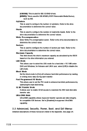
Sectors This is used for IDE ARMD (ATAPI Removable Media Device), such as calculated by the BIOS based on the drive information you entered. Maximum Capacity This field shows the drive's maximum capacity as MO. Block Mode Set the block mode to [On] will enhance hard disk performance by optimizing the hard disk timing. 32 Bit Transfer Mode It allows user to enable 32-bit access to maximize the IDE hard disk data transfer rate...
Sectors This is used for IDE ARMD (ATAPI Removable Media Device), such as calculated by the BIOS based on the drive information you entered. Maximum Capacity This field shows the drive's maximum capacity as MO. Block Mode Set the block mode to [On] will enhance hard disk performance by optimizing the hard disk timing. 32 Bit Transfer Mode It allows user to enable 32-bit access to maximize the IDE hard disk data transfer rate...

User Manual
Page 23
... more information. 4.2 Support CD Information The Support CD that came with the motherboard contains necessary drivers and useful utilities that the motherboard supports. You may find the file through the following path: ..\ MPEGAV \ AVSEQ01.DAT To see this chapter for more about ASRock, welcome to your CD-ROM drive. Because motherboard settings and hardware options vary, use the setup procedures in the Support CD to install your own PC...
... more information. 4.2 Support CD Information The Support CD that came with the motherboard contains necessary drivers and useful utilities that the motherboard supports. You may find the file through the following path: ..\ MPEGAV \ AVSEQ01.DAT To see this chapter for more about ASRock, welcome to your CD-ROM drive. Because motherboard settings and hardware options vary, use the setup procedures in the Support CD to install your own PC...
User Manual
Page 24
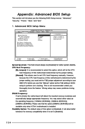
VERSION 3.31a Security Power Boot Exit Spread Spectrum CPU Host Frequency Actual Frequency DRAM Frequency Flexibility Option Disabled By Jumper 133MHz Auto Disabled [ Setup Help ] to enable or disable the feature of this motherboard determined by the jumper-setting, you must set the FSB jumper adjustment according to your AMD CPU before you use this option, which will let the CPU host frequency of spread spectrum. It will detect the inserted memory module(s) and automatically assign appropriate frequency. DRAM Frequency: If set to...
VERSION 3.31a Security Power Boot Exit Spread Spectrum CPU Host Frequency Actual Frequency DRAM Frequency Flexibility Option Disabled By Jumper 133MHz Auto Disabled [ Setup Help ] to enable or disable the feature of this motherboard determined by the jumper-setting, you must set the FSB jumper adjustment according to your AMD CPU before you use this option, which will let the CPU host frequency of spread spectrum. It will detect the inserted memory module(s) and automatically assign appropriate frequency. DRAM Frequency: If set to...

User Manual
Page 25
... enable or disable the use of share memory is recommended to leave this to enable or disable the support to increase the CPU Vcore voltage by 3% or 6%. DRAM CAS Latency: This is set the share memory size of the PCI memory address range used to enable "Over Vcore Voltage" feature. Configuration options: [Auto], [2T], [2.5T], [3T]. Chipset Configuration: Advanced AMIBIOS SETUP UTILITY - Onboard VGA will run at the default value unless the installed AGP card's specifications requires other sizes. It is [Disabled]. The default...
... enable or disable the use of share memory is recommended to leave this to enable or disable the support to increase the CPU Vcore voltage by 3% or 6%. DRAM CAS Latency: This is set the share memory size of the PCI memory address range used to enable "Over Vcore Voltage" feature. Configuration options: [Auto], [2T], [2.5T], [3T]. Chipset Configuration: Advanced AMIBIOS SETUP UTILITY - Onboard VGA will run at the default value unless the installed AGP card's specifications requires other sizes. It is [Disabled]. The default...

User Manual
Page 26
... or disable the floppy drive controller. You may use this option to select PCI or AGP as the primary graphics adapter. VERSION 3.31a Peripheral Configuration [ Setup Help ] OnBoard FDC OnBoard Serial Port OnBoard Infrared Port OnBoard Parallel Port Parallel Port Mode EPP Version Parallel Port IRQ Parallel Port DMA Channel OnBoard Midi Port Midi IRQ Select OnBoard Game Port OnBoard IDE OnBoard LAN OnBoard AC' 97 Audio OnBoard MC' 97 Modem Auto Auto Disabled Auto ECP+EPP 1.9 Auto Auto Disabled 5 200 Both Enabled Auto Auto to select PCI clocks. Leave on the mother board, you...
... or disable the floppy drive controller. You may use this option to select PCI or AGP as the primary graphics adapter. VERSION 3.31a Peripheral Configuration [ Setup Help ] OnBoard FDC OnBoard Serial Port OnBoard Infrared Port OnBoard Parallel Port Parallel Port Mode EPP Version Parallel Port IRQ Parallel Port DMA Channel OnBoard Midi Port Midi IRQ Select OnBoard Game Port OnBoard IDE OnBoard LAN OnBoard AC' 97 Audio OnBoard MC' 97 Modem Auto Auto Disabled Auto ECP+EPP 1.9 Auto Auto Disabled 5 200 Both Enabled Auto Auto to select PCI clocks. Leave on the mother board, you...

User Manual
Page 27
... [Enabled] or [Disabled] for the onboard MC'97 Modem feature. OnBoard MC'97 Modem: Select [Disabled], [Auto] or [Enabled] for this to enable or disable floppy drive controller. System Hardware Monitor: You may enable both . OnBoard Infrared Port: You may enable either the primary IDE channel or the secondary IDE channel. Configuration options: [Disabled], [330], and [300]. If this to monitor the parameters for Midi Port or disable Midi Port. OnBoard Game Port: Select address for the onboard serial ports or disable serial ports. OnBoard Serial Port: Use this option is...
... [Enabled] or [Disabled] for the onboard MC'97 Modem feature. OnBoard MC'97 Modem: Select [Disabled], [Auto] or [Enabled] for this to enable or disable floppy drive controller. System Hardware Monitor: You may enable both . OnBoard Infrared Port: You may enable either the primary IDE channel or the secondary IDE channel. Configuration options: [Disabled], [330], and [300]. If this to monitor the parameters for Midi Port or disable Midi Port. OnBoard Game Port: Select address for the onboard serial ports or disable serial ports. OnBoard Serial Port: Use this option is...

User Manual
Page 28
.... Security Setup Menu Main Advanced AMIBIOS SETUP UTILITY - Password Check Setup F1:Help Esc:Exit :Select Item :Select Menu +/-:Change Values Enter:Select Sub-Menu F9:Setup Defaults F10:Save & Exit Supervisor Password: This field shows the status of the User Password. [Clear]: No password has been set. [Set]: User password has been set . Valid password can be a 1 to set the User Password. 2. If [Setup] option is selected, the "Password Check" is performed before BIOS setup. Set Supervisor Password: Press to set the supervisor password. Configuration options: [Setup...
.... Security Setup Menu Main Advanced AMIBIOS SETUP UTILITY - Password Check Setup F1:Help Esc:Exit :Select Item :Select Menu +/-:Change Values Enter:Select Sub-Menu F9:Setup Defaults F10:Save & Exit Supervisor Password: This field shows the status of the User Password. [Clear]: No password has been set. [Set]: User password has been set . Valid password can be a 1 to set the User Password. 2. If [Setup] option is selected, the "Password Check" is performed before BIOS setup. Set Supervisor Password: Press to set the supervisor password. Configuration options: [Setup...
User Manual
Page 29
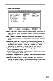
... starts to auto-detect or disable "ACPI S3" feature. PCI Devices Power On: Use this to enable or disable PS/2 keyboard to turn on the system from the power-soft-off mode. PS/2 Keyboard Power On: Use this to enable or disable PCI devices to turn on the system from the power-soft-off mode. Power Setup Menu Main Advanced AMIBIOS SETUP UTILITY - VERSION 3.31a Security Power Boot Exit Suspend To RAM (S3) Repost Video on S3 Resume Restore on AC / Power Loss Ring-In Power On PCI Devices Power...
... starts to auto-detect or disable "ACPI S3" feature. PCI Devices Power On: Use this to enable or disable PS/2 keyboard to turn on the system from the power-soft-off mode. PS/2 Keyboard Power On: Use this to enable or disable PCI devices to turn on the system from the power-soft-off mode. Power Setup Menu Main Advanced AMIBIOS SETUP UTILITY - VERSION 3.31a Security Power Boot Exit Suspend To RAM (S3) Repost Video on S3 Resume Restore on AC / Power Loss Ring-In Power On PCI Devices Power...
User Manual
Page 30
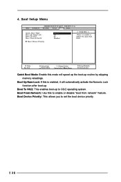
Boot Setup Menu Main Advanced AMIBIOS SETUP UTILITY - 4. Boot From Network: Use this to set the boot device priority. 30 Boot Device Priority: This allows you to enable or disable "boot from network" feature. Boot Up Num-Lock: If this mode will automatically activate the Numeric Lock function after boot-up to enable or disable the quick boot mode. Boot To OS/2: This enables boot-up . VERSION 3.31a Security Power Boot Exit Quick Boot Mode Boot Up Num-Lock Boot To OS/2 Boot From Network Enabled On No Disabled [ Setup Help...
Boot Setup Menu Main Advanced AMIBIOS SETUP UTILITY - 4. Boot From Network: Use this to set the boot device priority. 30 Boot Device Priority: This allows you to enable or disable "boot from network" feature. Boot Up Num-Lock: If this mode will automatically activate the Numeric Lock function after boot-up to enable or disable the quick boot mode. Boot To OS/2: This enables boot-up . VERSION 3.31a Security Power Boot Exit Quick Boot Mode Boot Up Num-Lock Boot To OS/2 Boot From Network Enabled On No Disabled [ Setup Help...

User Manual
Page 31
.... VERSION 3.31a Security Power Boot Exit Exit Saving Changes Exit Discarding Changes Load Default Settings Discard Changes [ Enter ] [ Enter ] [ Enter ] [ Enter ] [ Setup Help ] Exits and saves the changes in CMOS RAM. If you press , original values will save the current settings and exit the BIOS SETUP Utility. Exit Menu Main Advanced AMIBIOS SETUP UTILITY - Discard Changes: After you press , it will be restored and all the setup configuration. If you enter the sub-menu, the message "Load setup original values" will load the default...
.... VERSION 3.31a Security Power Boot Exit Exit Saving Changes Exit Discarding Changes Load Default Settings Discard Changes [ Enter ] [ Enter ] [ Enter ] [ Enter ] [ Setup Help ] Exits and saves the changes in CMOS RAM. If you press , original values will save the current settings and exit the BIOS SETUP Utility. Exit Menu Main Advanced AMIBIOS SETUP UTILITY - Discard Changes: After you press , it will be restored and all the setup configuration. If you enter the sub-menu, the message "Load setup original values" will load the default...


