User Manual
Page 4
... 45 3.1 Introduction 45 3.1.1 BIOS Menu Bar 45 3.1.2 Navigation Keys 46 3.2 Main Screen 46 3.3 Advanced Screen 47 3.3.1 CPU Configuration 47 3.3.2 Chipset Configuration 52 3.3.3 ACPI Configuration 54 3.3.4 IDE Configuration 55 3.3.5 PCIPnP ...
... 45 3.1 Introduction 45 3.1.1 BIOS Menu Bar 45 3.1.2 Navigation Keys 46 3.2 Main Screen 46 3.3 Advanced Screen 47 3.3.1 CPU Configuration 47 3.3.2 Chipset Configuration 52 3.3.3 ACPI Configuration 54 3.3.4 IDE Configuration 55 3.3.5 PCIPnP ...
User Manual
Page 5
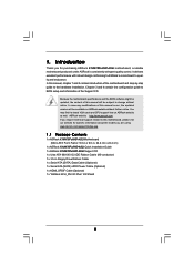
... are using. In this motherboard, please visit our website for specific information about the model you for purchasing ASRock K10N78FullHD-hSLI motherboard, a reliable motherboard produced under ASRock's consistently stringent quality control. Because the motherboard specifications and the BIOS software might be updated, the content of this manual will be subject to quality and endurance. In...
... are using. In this motherboard, please visit our website for specific information about the model you for purchasing ASRock K10N78FullHD-hSLI motherboard, a reliable motherboard produced under ASRock's consistently stringent quality control. Because the motherboard specifications and the BIOS software might be updated, the content of this manual will be subject to quality and endurance. In...
User Manual
Page 7
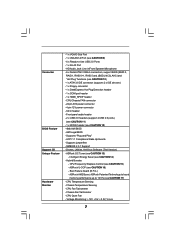
...: +12V, +5V, +3.3V, Vcore 7 Supports jumperfree - Hybrid Booster: - CPU/Chassis FAN connector - 24 pin ATX power connector - 4 pin 12V power connector - ASRock OC Tuner (see CAUTION 12) - 4Mb AMI BIOS - ASRock AM2 Boost: ASRock Patented Technology to boost memory performance up to 12.5% (see CAUTION 9) - 6 x Ready-to-Use USB 2.0 Ports - 1 x RJ-45 Port - Connector...
...: +12V, +5V, +3.3V, Vcore 7 Supports jumperfree - Hybrid Booster: - CPU/Chassis FAN connector - 24 pin ATX power connector - 4 pin 12V power connector - ASRock OC Tuner (see CAUTION 12) - 4Mb AMI BIOS - ASRock AM2 Boost: ASRock Patented Technology to boost memory performance up to 12.5% (see CAUTION 9) - 6 x Ready-to-Use USB 2.0 Ports - 1 x RJ-45 Port - Connector...
User Manual
Page 8
... refer to read "Untied Overclocking Technology" on page 18 for details. 3. If you adopt. ASRock website http://www.asrock.com 5. Currently, the Hybrid SLITM driver in the BIOS, applying Untied Overclocking Technology, or using the thirdparty overclocking tools. Overclocking may be HT3.0 (up...proper hardware configuration. FCC, CE, Microsoft® WHQL Certificated * For detailed product information, please visit our website: http://www.asrock.com WARNING Please realize that there is a certain risk involved with 64-bit CPU, there is supported depends on this motherboard,...
... refer to read "Untied Overclocking Technology" on page 18 for details. 3. If you adopt. ASRock website http://www.asrock.com 5. Currently, the Hybrid SLITM driver in the BIOS, applying Untied Overclocking Technology, or using the thirdparty overclocking tools. Overclocking may be HT3.0 (up...proper hardware configuration. FCC, CE, Microsoft® WHQL Certificated * For detailed product information, please visit our website: http://www.asrock.com WARNING Please realize that there is a certain risk involved with 64-bit CPU, there is supported depends on this motherboard,...
User Manual
Page 9
... computing performance. Please visit our website for further information. 10. ASRock website: http://www.asrock.com 14. In other than the recommended CPU bus frequencies may choose to disable this function in the BIOS setup, the memory performance will improve up to 12.5%, but the...Energy Saver function, please enable Cool 'n' Quiet option in the BIOS setup in ASRock OC Tuner. Please visit our website for the operation procedures of ASRock WiFi-802.11g or WiFi-802.11n module. This motherboard supports ASRock AM2 Boost overclocking technology. If your system. 9 Please visit ...
... computing performance. Please visit our website for further information. 10. ASRock website: http://www.asrock.com 14. In other than the recommended CPU bus frequencies may choose to disable this function in the BIOS setup, the memory performance will improve up to 12.5%, but the...Energy Saver function, please enable Cool 'n' Quiet option in the BIOS setup in ASRock OC Tuner. Please visit our website for the operation procedures of ASRock WiFi-802.11g or WiFi-802.11n module. This motherboard supports ASRock AM2 Boost overclocking technology. If your system. 9 Please visit ...

User Manual
Page 13
...PCI1- 2) 13 Secondary SATAII Connector 29 Internal Audio Connector: CD1 (Black) (SATAII_2 (PORT1)) 30 PCI Express 2.0 x16 Slot (PCIE2; 1.6 Motherboard Layout (K10N78FullHD-hSLI R2.0) 12 34 24.4cm (9.6-in) 56 PS2 Mouse PS2 Keyboard 1 PS2_USB_PW1 ATX12V1 CPU_FAN1 AT X P W R 1 24.4cm (9.6-in) AM2+ FSB2....AUDIO CODEC HDMI_SPDIF11 1 WIFI/E PCI2 26 25 SATAII 4Mb BIOS CMOS BATTERY USB6_7 1 RAID RoHS USB8_9 PANEL 1 PLED PWRBTN Super I/O SPEAKER1 1 1 CLRCMOS1 IR1 1 CHA_FAN1 COM1 1 1 1 HDLED RESET FLOPPY1 24 23 22 2120 19 18 K10N78FullHD-hSLI 7 8 9 10 11 12 13 14 15 16 ...
...PCI1- 2) 13 Secondary SATAII Connector 29 Internal Audio Connector: CD1 (Black) (SATAII_2 (PORT1)) 30 PCI Express 2.0 x16 Slot (PCIE2; 1.6 Motherboard Layout (K10N78FullHD-hSLI R2.0) 12 34 24.4cm (9.6-in) 56 PS2 Mouse PS2 Keyboard 1 PS2_USB_PW1 ATX12V1 CPU_FAN1 AT X P W R 1 24.4cm (9.6-in) AM2+ FSB2....AUDIO CODEC HDMI_SPDIF11 1 WIFI/E PCI2 26 25 SATAII 4Mb BIOS CMOS BATTERY USB6_7 1 RAID RoHS USB8_9 PANEL 1 PLED PWRBTN Super I/O SPEAKER1 1 1 CLRCMOS1 IR1 1 CHA_FAN1 COM1 1 1 1 HDLED RESET FLOPPY1 24 23 22 2120 19 18 K10N78FullHD-hSLI 7 8 9 10 11 12 13 14 15 16 ...

User Manual
Page 14
... 2) 13 Secondary SATAII Connector 29 Internal Audio Connector: CD1 (Black) (SATAII_2 (PORT1)) 30 PCI Express 2.0 x16 Slot (PCIE2; 1.7 Motherboard Layout (K10N78FullHD-hSLI R3.0) 12 34 24.4cm (9.6-in) 56 PS2 Mouse PS2 Keyboard 1 PS2_USB_PW1 ATX12V1 CPU_FAN1 AT X P W R 1 24.4cm (9.6-in) AM2+...SATAII_2(PORT 1) SATAII_4(PORT 3) SATAII_6(PORT 5) SATAII 4Mb BIOS CMOS BATTERY USB6_7 1 RAID RoHS USB8_9 PANEL 1 PLED PWRBTN Super I/O SPEAKER1 1 1 CLRCMOS1 IR1 1 CHA_FAN1 COM1 1 1 1 HDLED RESET FLOPPY1 26 25 24 23 22 2120 19 18 K10N78FullHD-hSLI 7 8 9 10 11 12 13 14 15 16 ...
... 2) 13 Secondary SATAII Connector 29 Internal Audio Connector: CD1 (Black) (SATAII_2 (PORT1)) 30 PCI Express 2.0 x16 Slot (PCIE2; 1.7 Motherboard Layout (K10N78FullHD-hSLI R3.0) 12 34 24.4cm (9.6-in) 56 PS2 Mouse PS2 Keyboard 1 PS2_USB_PW1 ATX12V1 CPU_FAN1 AT X P W R 1 24.4cm (9.6-in) AM2+...SATAII_2(PORT 1) SATAII_4(PORT 3) SATAII_6(PORT 5) SATAII 4Mb BIOS CMOS BATTERY USB6_7 1 RAID RoHS USB8_9 PANEL 1 PLED PWRBTN Super I/O SPEAKER1 1 1 CLRCMOS1 IR1 1 CHA_FAN1 COM1 1 1 1 HDLED RESET FLOPPY1 26 25 24 23 22 2120 19 18 K10N78FullHD-hSLI 7 8 9 10 11 12 13 14 15 16 ...

User Manual
Page 22
... your monitor cable to the connector on PCIE2 slot. Enter "Advanced" screen, and enter "Chipset Settings". Switch your BIOS change and exit BIOS setup. A. Set up the BIOS option "Primary Graphics Display" to PCIE2 slot (green). B. Supported PCI Express Card for the graphics cards update in the... proper installation procedures, please refer to the motherboard GPU, you are supported only with certain set the option "Hybrid SLI" to enter BIOS setup. For users using single monitor: If you can switch between GeForce® Boost mode (Boost Performance) and HybridPowerTM mode (Save Power...
... your monitor cable to the connector on PCIE2 slot. Enter "Advanced" screen, and enter "Chipset Settings". Switch your BIOS change and exit BIOS setup. A. Set up the BIOS option "Primary Graphics Display" to PCIE2 slot (green). B. Supported PCI Express Card for the graphics cards update in the... proper installation procedures, please refer to the motherboard GPU, you are supported only with certain set the option "Hybrid SLI" to enter BIOS setup. For users using single monitor: If you can switch between GeForce® Boost mode (Boost Performance) and HybridPowerTM mode (Save Power...

User Manual
Page 23
... Hybrid icon on the I/O shield. Step 3. Step 5. Press to [256MB] or [512MB]. And set the option "Hybrid SLI" to enter BIOS setup. For the proper installation procedures, please refer to [Onboard]. Install Hybrid SLITM driver from our support CD to your Windows® taskbar. Restart... your BIOS change and exit BIOS setup. HybridPowerTM Step 1. The default setting is in the following path of ASRock support CD: (There are two ASRock support CD in the motherboard gift box pack, please choose the one ...
... Hybrid icon on the I/O shield. Step 3. Step 5. Press to [256MB] or [512MB]. And set the option "Hybrid SLI" to enter BIOS setup. For the proper installation procedures, please refer to [Onboard]. Install Hybrid SLITM driver from our support CD to your Windows® taskbar. Restart... your BIOS change and exit BIOS setup. HybridPowerTM Step 1. The default setting is in the following path of ASRock support CD: (There are two ASRock support CD in the motherboard gift box pack, please choose the one ...

User Manual
Page 24
... 3. Boot into OS. Step 8. Connect the other monitor cable to section "Expansion Slots". Hybrid SLITM driver is in the following path of ASRock support CD: (There are two ASRock support CD in the motherboard gift box pack, please choose the one for Windows® VistaTM / VistaTM 64-bit.) ..\Drivers\Hybrid SLI driver... you will find the Hybrid icon on the I/O shield. Press to [32MB], [64MB], [128MB], [256MB] or [512MB]. Then set the option "Share Memory" to enter BIOS setup.
... 3. Boot into OS. Step 8. Connect the other monitor cable to section "Expansion Slots". Hybrid SLITM driver is in the following path of ASRock support CD: (There are two ASRock support CD in the motherboard gift box pack, please choose the one for Windows® VistaTM / VistaTM 64-bit.) ..\Drivers\Hybrid SLI driver... you will find the Hybrid icon on the I/O shield. Press to [32MB], [64MB], [128MB], [256MB] or [512MB]. Then set the option "Share Memory" to enter BIOS setup.
User Manual
Page 26
.... Connect the D-Sub monitor cable to this motherboard. Boot your primary monitor, and then select "Primary". Please make sure that you do not adjust the BIOS setup, the default value of the multi-monitor according to install them again. 5. If you can adjust the parameters of surround display feature. For Windows... is less than the total capability of this monitor". E. Right-click the display icon and select "Attached", if necessary. F. Click "Apply" or "OK" to enter BIOS setup. Repeat steps C through E for the diaplay icon identified by the number 2.
.... Connect the D-Sub monitor cable to this motherboard. Boot your primary monitor, and then select "Primary". Please make sure that you do not adjust the BIOS setup, the default value of the multi-monitor according to install them again. 5. If you can adjust the parameters of surround display feature. For Windows... is less than the total capability of this monitor". E. Right-click the display icon and select "Attached", if necessary. F. Click "Apply" or "OK" to enter BIOS setup. Repeat steps C through E for the diaplay icon identified by the number 2.

User Manual
Page 28
A. Install "Onboard HDMI HD Audio Driver" from ASRock Support CD to [Auto]. Step 3: Reboot your system. For Windows® VistaTM / VistaTM 64-bit OS Step 1: Set up BIOS. Set the option "OnBoard HDMI HD Audio" to your system. Click "Hardware and Sound", and click "Sound"....Set the option "OnBoard HDMI HD Audio" to HDMI interface. Step 2: Install HDMI audio driver to set up your system. A. Enter BIOS SETUP UTILITY Advanced screen Chipset Configuration. B. Step 2: Enter Windows® to your system manually. Change the default setting "Speaker" to the...
A. Install "Onboard HDMI HD Audio Driver" from ASRock Support CD to [Auto]. Step 3: Reboot your system. For Windows® VistaTM / VistaTM 64-bit OS Step 1: Set up BIOS. Set the option "OnBoard HDMI HD Audio" to your system. Click "Hardware and Sound", and click "Sound"....Set the option "OnBoard HDMI HD Audio" to HDMI interface. Step 2: Install HDMI audio driver to set up your system. A. Enter BIOS SETUP UTILITY Advanced screen Chipset Configuration. B. Step 2: Enter Windows® to your system manually. Change the default setting "Speaker" to the...

User Manual
Page 29
... system password, date, time, and system setup parameters. To clear and reset the system parameters to clear the CMOS when you just finish updating the BIOS, you must boot up events. If no jumper cap is placed on pins, the jumper is "Short". Note: To select +5VSB, it down before you... not clear the CMOS right after you to enable (see p.13/14, No. 14) 1_2 2_3 Default Clear CMOS Note: CLRCMOS1 allows you update the BIOS. If you need to default setup, please turn off the computer and unplug the power cord from the power supply.
... system password, date, time, and system setup parameters. To clear and reset the system parameters to clear the CMOS when you just finish updating the BIOS, you must boot up events. If no jumper cap is placed on pins, the jumper is "Short". Note: To select +5VSB, it down before you... not clear the CMOS right after you to enable (see p.13/14, No. 14) 1_2 2_3 Default Clear CMOS Note: CLRCMOS1 allows you update the BIOS. If you need to default setup, please turn off the computer and unplug the power cord from the power supply.

User Manual
Page 32
... This is an interface for HD audio panel only. B. Set the Front Panel Control option from [Auto] to MIC2_L. Connect Mic_IN (MIC) to [Enabled]. D. Enter BIOS Setup Utility. For Windows® XP / XP 64-bit OS: Click "Audio I/O", select "Connector Settings" , choose "Disable front panel jack detection", and save the change...
... This is an interface for HD audio panel only. B. Set the Front Panel Control option from [Auto] to MIC2_L. Connect Mic_IN (MIC) to [Enabled]. D. Enter BIOS Setup Utility. For Windows® XP / XP 64-bit OS: Click "Audio I/O", select "Connector Settings" , choose "Disable front panel jack detection", and save the change...

User Manual
Page 40
...WindowsXP 2. 2.15 Driver Installation Guide To install the drivers to your system, please insert the support CD to boot your system. (There are two ASRock Support CD in the motherboard gift box pack, please choose the one for Windows® XP / XP 64-bit.) B. Using SATA / SATAII ...5. B. During POST at the beginning of system boot-up to bottom side to install those required drivers. D. Enter BIOS SETUP UTILITY Advanced screen IDE Configuration. A. Insert the ASRock Support CD into your optical drive to your optical drive first. Please select CD-ROM as the boot device. Then you...
...WindowsXP 2. 2.15 Driver Installation Guide To install the drivers to your system, please insert the support CD to boot your system. (There are two ASRock Support CD in the motherboard gift box pack, please choose the one for Windows® XP / XP 64-bit.) B. Using SATA / SATAII ...5. B. During POST at the beginning of system boot-up to bottom side to install those required drivers. D. Enter BIOS SETUP UTILITY Advanced screen IDE Configuration. A. Insert the ASRock Support CD into your optical drive to your optical drive first. Please select CD-ROM as the boot device. Then you...

User Manual
Page 41
... the OS you install. Please select B for Windows® XP in AHCI mode. A. " page, please insert the ASRock Support CD into the floppy diskette. E. STEP 3: Set Up BIOS. When prompted, insert the SATA / SATAII driver diskette containing the NVIDIA® AHCI driver. Select the driver to install ... press any key. STEP 4: Install Windows® XP / XP 64-bit OS on your system, and follow step 1 to set up the BIOS option "SATA Operation Mode" to [non-RAID]. The drivers are in the following path in AHCI mode. NVIDIA nForce Storage Controller (required) Windows XP64...
... the OS you install. Please select B for Windows® XP in AHCI mode. A. " page, please insert the ASRock Support CD into the floppy diskette. E. STEP 3: Set Up BIOS. When prompted, insert the SATA / SATAII driver diskette containing the NVIDIA® AHCI driver. Select the driver to install ... press any key. STEP 4: Install Windows® XP / XP 64-bit OS on your system, and follow step 1 to set up the BIOS option "SATA Operation Mode" to [non-RAID]. The drivers are in the following path in AHCI mode. NVIDIA nForce Storage Controller (required) Windows XP64...

User Manual
Page 42
... Guide 42 STEP 2: Make a SATA / SATAII Driver Diskette. (There are two ASRock Support CD in the motherboard gift box pack, please choose the one for proper configuration. B. B. STEP 3: Set Up BIOS. STEP 4: Use "RAID Installation Guide" to install Windows® XP or Windows&#...174; XP 64-bit on your SATA / SATAII HDDs with RAID functions, please follow below steps. STEP 1: Set Up BIOS. A. Enter BIOS SETUP UTILITY Advanced screen IDE Configuration. STEP 2: Install Windows® VistaTM / VistaTM 64-bit OS on your system. 2.17 Installing...
... Guide 42 STEP 2: Make a SATA / SATAII Driver Diskette. (There are two ASRock Support CD in the motherboard gift box pack, please choose the one for proper configuration. B. B. STEP 3: Set Up BIOS. STEP 4: Use "RAID Installation Guide" to install Windows® XP or Windows&#...174; XP 64-bit on your SATA / SATAII HDDs with RAID functions, please follow below steps. STEP 1: Set Up BIOS. A. Enter BIOS SETUP UTILITY Advanced screen IDE Configuration. STEP 2: Install Windows® VistaTM / VistaTM 64-bit OS on your system. 2.17 Installing...

User Manual
Page 43
... HDDs with RAID functions, please follow the instruction to install Windows® VistaTM / Windows® VistaTM 64-bit OS on your system. Enter BIOS SETUP UTILITY Advanced screen IDE Configuration. STEP 2: Use "RAID Installation Guide" to [RAID]. Then, please set the RAID configuration by using the ...motherboard gift box pack, please choose the one .) NOTE. After reading the floppy disk, the drivers will be presented. " page, please insert the ASRock Support CD into the optical drive to boot your system, and follow below : A. STEP 5: Install Windows® XP / Windows® XP 64...
... HDDs with RAID functions, please follow the instruction to install Windows® VistaTM / Windows® VistaTM 64-bit OS on your system. Enter BIOS SETUP UTILITY Advanced screen IDE Configuration. STEP 2: Use "RAID Installation Guide" to [RAID]. Then, please set the RAID configuration by using the ...motherboard gift box pack, please choose the one .) NOTE. After reading the floppy disk, the drivers will be presented. " page, please insert the ASRock Support CD into the optical drive to boot your system, and follow below : A. STEP 5: Install Windows® XP / Windows® XP 64...

User Manual
Page 44
... the Support CD: .. \ RAID Installation Guide 2 . 1 8 Untied Overclocking Technology This motherboard supports Untied Overclocking Technology, which means during overclocking, but PCI / PCIE buses are in BIOS first. .. \ I386 \ Vista (For Windows® VistaTM OS) .. \ AMD64 \ Vista64 (For Windows® VistaTM 64-bit OS) After that FSB can operate under a ... [CPU, PCIE, Async.]. Please refer to the warning on SATA / SATAII HDDs, you enable Untied Overclocking function, please enter "Overclock Mode" option of BIOS setup to set the selection from [Auto] to fixed PCI / PCIE buses. NOTE.
... the Support CD: .. \ RAID Installation Guide 2 . 1 8 Untied Overclocking Technology This motherboard supports Untied Overclocking Technology, which means during overclocking, but PCI / PCIE buses are in BIOS first. .. \ I386 \ Vista (For Windows® VistaTM OS) .. \ AMD64 \ Vista64 (For Windows® VistaTM 64-bit OS) After that FSB can operate under a ... [CPU, PCIE, Async.]. Please refer to the warning on SATA / SATAII HDDs, you enable Untied Overclocking function, please enter "Overclock Mode" option of BIOS setup to set the selection from [Auto] to fixed PCI / PCIE buses. NOTE.

User Manual
Page 45
... is constantly being updated, the following selections: Main To set up the system time/date information Advanced To set up the advanced BIOS features H/W Monitor To display current hardware status Boot To set up the default system device to get into the sub screen. 45 Please press during ... to locate and load the Operating System Security To set up the computer. You may not exactly match what you wish to configure your screen. 3.1.1 BIOS Menu Bar The top of the screen has a menu bar with its test routines. 3. If you see on the motherboard stores the...
... is constantly being updated, the following selections: Main To set up the system time/date information Advanced To set up the advanced BIOS features H/W Monitor To display current hardware status Boot To set up the default system device to get into the sub screen. 45 Please press during ... to locate and load the Operating System Security To set up the computer. You may not exactly match what you wish to configure your screen. 3.1.1 BIOS Menu Bar The top of the screen has a menu bar with its test routines. 3. If you see on the motherboard stores the...


