
User Manual
Page 4
... 1.2 Specifications 2 1.3 Motherboard Layout 5 1.4 I/O Panel 7 Chapter 2 Installation 9 2.1 Installing Memory Modules (SO-DIMM) 10 2.2 Expansion Slot (PCI Express Slot) 12 2.3 Jumpers Setup 13 2.4 Onboard Headers and Connectors 14 2.5 M.2 WiFi/BT Module Installation Guide 18 Chapter 3 Software and Utilities Operation 20 3.1 Installing Drivers 20 3.2 ASRock Live Update & APP Shop 21 3.2.1 UI Overview 21 3.2.2 Apps 22 3.2.3 BIOS & Drivers 25 3.2.4 Setting 26 Chapter 4 UEFI SETUP UTILITY 27 4.1 Introduction 27 4.1.1 UEFI Menu Bar 27 4.1.2 Navigation Keys 28
... 1.2 Specifications 2 1.3 Motherboard Layout 5 1.4 I/O Panel 7 Chapter 2 Installation 9 2.1 Installing Memory Modules (SO-DIMM) 10 2.2 Expansion Slot (PCI Express Slot) 12 2.3 Jumpers Setup 13 2.4 Onboard Headers and Connectors 14 2.5 M.2 WiFi/BT Module Installation Guide 18 Chapter 3 Software and Utilities Operation 20 3.1 Installing Drivers 20 3.2 ASRock Live Update & APP Shop 21 3.2.1 UI Overview 21 3.2.2 Apps 22 3.2.3 BIOS & Drivers 25 3.2.4 Setting 26 Chapter 4 UEFI SETUP UTILITY 27 4.1 Introduction 27 4.1.1 UEFI Menu Bar 27 4.1.2 Navigation Keys 28
User Manual
Page 6
...-step installation guides. Chapter 3 contains the operation guide of the BIOS setup. If you are using. You may find the latest VGA cards and CPU support list on ASRock's website without notice. Chapter 4 contains the configuration guide of the software and utilities. ASRock website http://www.asrock.com. 1.1 Package Contents • ASRock J4205-ITX/J3455-ITX Motherboard (Mini-ITX Form Factor) • ASRock J4205-ITX/J3455-ITX Quick Installation Guide • ASRock J4205-ITX/J3455-ITX Support CD • 2 x Serial ATA (SATA) Data Cables (Optional) • 1 x I/O Panel Shield...
...-step installation guides. Chapter 3 contains the operation guide of the BIOS setup. If you are using. You may find the latest VGA cards and CPU support list on ASRock's website without notice. Chapter 4 contains the configuration guide of the software and utilities. ASRock website http://www.asrock.com. 1.1 Package Contents • ASRock J4205-ITX/J3455-ITX Motherboard (Mini-ITX Form Factor) • ASRock J4205-ITX/J3455-ITX Quick Installation Guide • ASRock J4205-ITX/J3455-ITX Support CD • 2 x Serial ATA (SATA) Data Cables (Optional) • 1 x I/O Panel Shield...

User Manual
Page 7
... • Supports Auto Lip Sync, xvYCC and HBR (High Bit Rate Audio) with max. buffered memory • Max. resolution up to 4K x 2K (4096x2160) @ 60Hz • Supports DVI-D with DVI-D and HDMI Ports 2 English capacity of system memory: 16GB Expansion Slot • 1 x PCI Express 2.0 x1 Slot • 1 x M.2 Socket (Key E), supports type 2230 WiFi/BT module Graphics • Integrated Intel® HD Graphics 505: 18 EUs inside (Up to 800MHz) (for J4205-ITX) • Integrated...
... • Supports Auto Lip Sync, xvYCC and HBR (High Bit Rate Audio) with max. buffered memory • Max. resolution up to 4K x 2K (4096x2160) @ 60Hz • Supports DVI-D with DVI-D and HDMI Ports 2 English capacity of system memory: 16GB Expansion Slot • 1 x PCI Express 2.0 x1 Slot • 1 x M.2 Socket (Key E), supports type 2230 WiFi/BT module Graphics • Integrated Intel® HD Graphics 505: 18 EUs inside (Up to 800MHz) (for J4205-ITX) • Integrated...

User Manual
Page 8
...; Supports PXE Rear Panel I/O • 1 x PS/2 Mouse Port • 1 x PS/2 Keyboard Port • 1 x D-Sub Port • 1 x DVI-D Port • 1 x HDMI Port • 1 x Optical SPDIF Out Port • 2 x USB 2.0 Ports (Supports ESD Protection (ASRock Full Spike Protection)) • 2 x USB 3.0 Ports (Supports ESD Protection (ASRock Full Spike Protection)) • 1 x RJ-45 LAN Port with LED (ACT/LINK LED and SPEED LED) • HD Audio Jacks: Side Speaker / Rear Speaker / Central / Bass / Line in / Front Speaker / Microphone Storage • 2 x SATA3 6.0 Gb/s Connectors, support NCQ, AHCI...
...; Supports PXE Rear Panel I/O • 1 x PS/2 Mouse Port • 1 x PS/2 Keyboard Port • 1 x D-Sub Port • 1 x DVI-D Port • 1 x HDMI Port • 1 x Optical SPDIF Out Port • 2 x USB 2.0 Ports (Supports ESD Protection (ASRock Full Spike Protection)) • 2 x USB 3.0 Ports (Supports ESD Protection (ASRock Full Spike Protection)) • 1 x RJ-45 LAN Port with LED (ACT/LINK LED and SPEED LED) • HD Audio Jacks: Side Speaker / Rear Speaker / Central / Bass / Line in / Front Speaker / Microphone Storage • 2 x SATA3 6.0 Gb/s Connectors, support NCQ, AHCI...

User Manual
Page 9
... Speaker Header • 1 x CPU Fan Connector (3-pin) • 1 x Chassis Fan Connector (3-pin) • 1 x 24 pin ATX Power Connector • 1 x Front Panel Audio Connector • 2 x USB 2.0 Headers (Support 3 USB 2.0 ports) (Supports ESD Protection (ASRock Full Spike Protection)) • 1 x USB 3.0 Header (Supports 2 USB 3.0 ports) (Supports ESD Protection (ASRock Full Spike Protection)) * USB3_0_1 is required) * For detailed product information, please visit our website: http://www.asrock.com English 4 BIOS Feature • AMI UEFI Legal BIOS with GUI support • Supports Plug...
... Speaker Header • 1 x CPU Fan Connector (3-pin) • 1 x Chassis Fan Connector (3-pin) • 1 x 24 pin ATX Power Connector • 1 x Front Panel Audio Connector • 2 x USB 2.0 Headers (Support 3 USB 2.0 ports) (Supports ESD Protection (ASRock Full Spike Protection)) • 1 x USB 3.0 Header (Supports 2 USB 3.0 ports) (Supports ESD Protection (ASRock Full Spike Protection)) * USB3_0_1 is required) * For detailed product information, please visit our website: http://www.asrock.com English 4 BIOS Feature • AMI UEFI Legal BIOS with GUI support • Supports Plug...
User Manual
Page 14
... electricity to the motherboard's components, NEVER place your chassis to unplug the power cord before you handle the components. • Hold components by the edges and do so may damage the motherboard. 9 English J4205-ITX J3455-ITX Chapter 2 Installation This is a Mini-ITX form factor motherboard. Failure to do not touch the ICs. • Whenever you install motherboard components or change any components, place...
... electricity to the motherboard's components, NEVER place your chassis to unplug the power cord before you handle the components. • Hold components by the edges and do so may damage the motherboard. 9 English J4205-ITX J3455-ITX Chapter 2 Installation This is a Mini-ITX form factor motherboard. Failure to do not touch the ICs. • Whenever you install motherboard components or change any components, place...

User Manual
Page 17
... graphics compability, the BIOS is unplugged. Before installing an expansion card, please make necessary hardware settings for PCI Express cards with x1 lane width cards. 2.2 Expansion Slot (PCI Express Slot) There is used for the card before you start the installation. Please read the documentation of the expansion card and make sure that the power supply is switched off or the power cord is set to "boot from Onboard VGA" as default even the user install a VGA card on the motherboard. PCIe slot: PCIE1 (PCIe...
... graphics compability, the BIOS is unplugged. Before installing an expansion card, please make necessary hardware settings for PCI Express cards with x1 lane width cards. 2.2 Expansion Slot (PCI Express Slot) There is used for the card before you start the installation. Please read the documentation of the expansion card and make sure that the power supply is switched off or the power cord is set to "boot from Onboard VGA" as default even the user install a VGA card on the motherboard. PCIe slot: PCIE1 (PCIe...

User Manual
Page 18
... you to default setup, please turn off the computer and unplug the power cord from the power supply. Please be noted that the password, date, time, and user default profile will be detected. To clear and reset the system parameters to clear the data in CMOS. English 13 However, please do the clear-CMOS action. If you update the BIOS. Please adjust the BIOS option "Clear Status" to clear the CMOS when...
... you to default setup, please turn off the computer and unplug the power cord from the power supply. Please be noted that the password, date, time, and user default profile will be detected. To clear and reset the system parameters to clear the data in CMOS. English 13 However, please do the clear-CMOS action. If you update the BIOS. Please adjust the BIOS option "Clear Status" to clear the CMOS when...

User Manual
Page 21
... use a 20-pin ATX power supply, please plug it to the front panel audio header by the steps below: A. C. PCIRST# FRAME PCICLK This connector supports Trusted Platform Module (TPM) system, which can securely store keys, digital certificates, passwords, and data. ATX Power Connector (24-pin ATXPWR1) (see p.5, No. 4) TPM Header (17-pin TPMS1) (see p.5, No. 10) GND FAN_VOLTAGE CHA_FAN_SPEED Please connect fan cable to the fan connector and match the black wire to install your system. 2. High...
... use a 20-pin ATX power supply, please plug it to the front panel audio header by the steps below: A. C. PCIRST# FRAME PCICLK This connector supports Trusted Platform Module (TPM) system, which can securely store keys, digital certificates, passwords, and data. ATX Power Connector (24-pin ATXPWR1) (see p.5, No. 4) TPM Header (17-pin TPMS1) (see p.5, No. 10) GND FAN_VOLTAGE CHA_FAN_SPEED Please connect fan cable to the fan connector and match the black wire to install your system. 2. High...

User Manual
Page 23
... size and versatile card edge connector that the module only fits in one orientation. Installing the WiFi/BT module Step 1 Prepare a type 2230 WiFi/BT module and the screw. The M.2 Socket (Key E) supports type 2230 WiFi/BT module. * The M.2 socket does not support SATA M.2 SSDs. Please be aware that aims to be used. Module Type: Type2230 PCB Length: 3cm Step 2 Find the nut location to replace...
... size and versatile card edge connector that the module only fits in one orientation. Installing the WiFi/BT module Step 1 Prepare a type 2230 WiFi/BT module and the screw. The M.2 Socket (Key E) supports type 2230 WiFi/BT module. * The M.2 socket does not support SATA M.2 SSDs. Please be aware that aims to be used. Module Type: Type2230 PCB Length: 3cm Step 2 Find the nut location to replace...
User Manual
Page 25
... auto-detected and listed on the file "ASRSETUP.EXE" in your CD-ROM drive. Therefore, the drivers you install can work properly. "KB2720599": http://support.microsoft.com/kb/2720599/en-us 20 English Utilities Menu The Utilities Menu shows the application software that enhance the motherboard's features. The CD automatically displays the Main Menu if "AUTORUN" is enabled in the Support CD to display the menu. If the Main Menu does not appear automatically, locate...
... auto-detected and listed on the file "ASRSETUP.EXE" in your CD-ROM drive. Therefore, the drivers you install can work properly. "KB2720599": http://support.microsoft.com/kb/2720599/en-us 20 English Utilities Menu The Utilities Menu shows the application software that enhance the motherboard's features. The CD automatically displays the Main Menu if "AUTORUN" is enabled in the Support CD to display the menu. If the Main Menu does not appear automatically, locate...
User Manual
Page 26
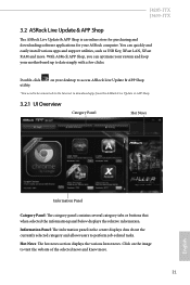
... can quickly and easily install various apps and support utilities, such as USB Key, XFast LAN, XFast RAM and more . 21 English on the image to visit the website of the selected news and know more . J4205-ITX J3455-ITX 3.2 ASRock Live Update & APP Shop The ASRock Live Update & APP Shop is an online store for purchasing and downloading software applications for your motherboard up to date...
... can quickly and easily install various apps and support utilities, such as USB Key, XFast LAN, XFast RAM and more . 21 English on the image to visit the website of the selected news and know more . J4205-ITX J3455-ITX 3.2 ASRock Live Update & APP Shop The ASRock Live Update & APP Shop is an online store for purchasing and downloading software applications for your motherboard up to date...
User Manual
Page 32
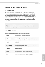
... system configurations Tool Useful tools H/W Monitor Displays current hardware status Security For security settings Boot For configuring boot settings and boot priority Exit Exit the current screen or the UEFI Setup Utility English 27 If you wish to configure your screen. 4.1.1 UEFI Menu Bar The top of the screen has a menu bar with its test routines. You may also restart by pressing the reset button on the system chassis. You may run the UEFI SETUP UTILITY...
... system configurations Tool Useful tools H/W Monitor Displays current hardware status Security For security settings Boot For configuring boot settings and boot priority Exit Exit the current screen or the UEFI Setup Utility English 27 If you wish to configure your screen. 4.1.1 UEFI Menu Bar The top of the screen has a menu bar with its test routines. You may also restart by pressing the reset button on the system chassis. You may run the UEFI SETUP UTILITY...

User Manual
Page 37
...the size of memory that is allocated to [Onboard] (boot from onboard VGA). 4.3.2 Chipset Configuration DRAM Frequency If [Auto] is [Auto]. Primary Graphics Adapter Select a primary VGA. *To ensure better graphics compatibility, the default is installed. 32 English DRAM Voltage (1.35V) Use this to enable onboard HD audio and automatically disable it when a sound card is set to the integrated graphics processor when the system boots up. Set to Auto to configure DRAM Voltage. Onboard HD Audio Enable/disable onboard HD audio. The default value is selected, the motherboard will...
...the size of memory that is allocated to [Onboard] (boot from onboard VGA). 4.3.2 Chipset Configuration DRAM Frequency If [Auto] is [Auto]. Primary Graphics Adapter Select a primary VGA. *To ensure better graphics compatibility, the default is installed. 32 English DRAM Voltage (1.35V) Use this to enable onboard HD audio and automatically disable it when a sound card is set to the integrated graphics processor when the system boots up. Set to Auto to configure DRAM Voltage. Onboard HD Audio Enable/disable onboard HD audio. The default value is selected, the motherboard will...

User Manual
Page 38
... start to boot up when the power recovers. WAN Radio Enable/disable the WiFi module's connectivity. If [Power Off] is selected, the system will also automatically switch off when the system is shut down. If [Power On] is selected, the power will be switched off the Power and Keyboard LEDs when the system enters into Standby/Hibernation mode. 33 English Onboard LAN Enable or disable the onboard network interface controller. Deep S5 Configure deep sleep mode...
... start to boot up when the power recovers. WAN Radio Enable/disable the WiFi module's connectivity. If [Power Off] is selected, the system will also automatically switch off when the system is shut down. If [Power On] is selected, the power will be switched off the Power and Keyboard LEDs when the system enters into Standby/Hibernation mode. 33 English Onboard LAN Enable or disable the onboard network interface controller. Deep S5 Configure deep sleep mode...

User Manual
Page 40
Serial Port Address Select the address of the Serial port. 35 English 4.3.4 Super IO Configuration J4205-ITX J3455-ITX Serial Port 1 Enable or disable the Serial port 1.
Serial Port Address Select the address of the Serial port. 35 English 4.3.4 Super IO Configuration J4205-ITX J3455-ITX Serial Port 1 Enable or disable the Serial port 1.
User Manual
Page 45
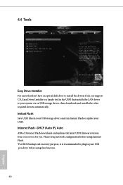
... Flash Save UEFI files in your USB storage device and run Instant Flash to plug in the UEFI that don't have an optical disk drive to install the drivers from our servers for you. DHCP (Auto IP), Auto ASRock Internet Flash downloads and updates the latest UEFI firmware version from our support CD, Easy Driver Installer is recommended to update your system via an USB storage device, then downloads and installs the other required drivers automatically. Please setup network configuration before using Internet Flash. *For BIOS backup and recovery...
... Flash Save UEFI files in your USB storage device and run Instant Flash to plug in the UEFI that don't have an optical disk drive to install the drivers from our servers for you. DHCP (Auto IP), Auto ASRock Internet Flash downloads and updates the latest UEFI firmware version from our support CD, Easy Driver Installer is recommended to update your system via an USB storage device, then downloads and installs the other required drivers automatically. Please setup network configuration before using Internet Flash. *For BIOS backup and recovery...
User Manual
Page 46
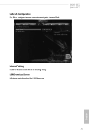
UEFI Download Server Select a server to configure internet connection settings for Internet Flash. Network Configuration Use this to download the UEFI firmware. English 41 J4205-ITX J3455-ITX Internet Setting Enable or disable sound effects in the setup utility.
UEFI Download Server Select a server to configure internet connection settings for Internet Flash. Network Configuration Use this to download the UEFI firmware. English 41 J4205-ITX J3455-ITX Internet Setting Enable or disable sound effects in the setup utility.

User Manual
Page 47
Configuration options: [Full On], [Automatic Mode] and [Manual]. Chassis Fan 1 Setting This allows you to monitor the status of the hardware on your system, including the parameters of the CPU temperature, motherboard temperature, fan speed and voltage. Case Open Feature Enable or disable Case Open Feature to set chassis fan 1's speed. The default value is [Full On]. 4.5 Hardware Health Event Monitoring Screen This section allows you to set CPU fan 1's speed. Configuration options: [Full On] and [Automatic Mode]. The default value is [Full On]. CPU Fan 1 Setting This...
Configuration options: [Full On], [Automatic Mode] and [Manual]. Chassis Fan 1 Setting This allows you to monitor the status of the hardware on your system, including the parameters of the CPU temperature, motherboard temperature, fan speed and voltage. Case Open Feature Enable or disable Case Open Feature to set chassis fan 1's speed. The default value is [Full On]. 4.5 Hardware Health Event Monitoring Screen This section allows you to set CPU fan 1's speed. Configuration options: [Full On] and [Automatic Mode]. The default value is [Full On]. CPU Fan 1 Setting This...

User Manual
Page 48
.... Leave it blank and press enter to support Windows 8.1 Secure Boot. Disable this section you may also clear the user password. Supervisor Password Set or change the supervisor/user password for the system. Users are unable to use discrete TPM Module. 43 English Intel(R) Platform Trust Technology Enable/disable Intel PTT in the UEFI Setup Utility. You may set or change the password for the user account. J4205-ITX J3455-ITX 4.6 Security Screen In this option to change the settings in ME.
.... Leave it blank and press enter to support Windows 8.1 Secure Boot. Disable this section you may also clear the user password. Supervisor Password Set or change the supervisor/user password for the system. Users are unable to use discrete TPM Module. 43 English Intel(R) Platform Trust Technology Enable/disable Intel PTT in the UEFI Setup Utility. You may set or change the password for the user account. J4205-ITX J3455-ITX 4.6 Security Screen In this option to change the settings in ME.


