User Manual
Page 4
... Express Slot) 12 2.3 Jumpers Setup 13 2.4 Onboard Headers and Connectors 14 Chapter 3 Software and Utilities Operation 18 3.1 Installing Drivers 18 3.2 ASRock Live Update & APP Shop 19 3.2.1 UI Overview 19 3.2.2 Apps 20 3.2.3 BIOS & Drivers 23 3.2.4 Setting 24 Chapter 4 UEFI SETUP UTILITY 25 4.1 Introduction 25 4.1.1 UEFI Menu Bar 25 4.1.2 Navigation Keys 26 4.2 Main Screen...
... Express Slot) 12 2.3 Jumpers Setup 13 2.4 Onboard Headers and Connectors 14 Chapter 3 Software and Utilities Operation 18 3.1 Installing Drivers 18 3.2 ASRock Live Update & APP Shop 19 3.2.1 UI Overview 19 3.2.2 Apps 20 3.2.3 BIOS & Drivers 23 3.2.4 Setting 24 Chapter 4 UEFI SETUP UTILITY 25 4.1 Introduction 25 4.1.1 UEFI Menu Bar 25 4.1.2 Navigation Keys 26 4.2 Main Screen...
User Manual
Page 6
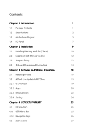
Chapter 3 contains the operation guide of the BIOS setup. If you are using. ASRock website http://www.asrock.com. 1.1 Package Contents • ASRock J3455M/J3355M Motherboard (Micro ATX Form Factor) • ASRock J3455M/J3355M Quick Installation Guide • ASRock J3455M/J3355M Support CD • 2 x Serial ATA (SATA) Data Cables ... latest VGA cards and CPU support list on ASRock's website without notice. Because the motherboard specifications and the BIOS software might be subject to quality and endurance. J3455M J3355M Chapter 1 Introduction Thank you for specific ...
Chapter 3 contains the operation guide of the BIOS setup. If you are using. ASRock website http://www.asrock.com. 1.1 Package Contents • ASRock J3455M/J3355M Motherboard (Micro ATX Form Factor) • ASRock J3455M/J3355M Quick Installation Guide • ASRock J3455M/J3355M Support CD • 2 x Serial ATA (SATA) Data Cables ... latest VGA cards and CPU support list on ASRock's website without notice. Because the motherboard specifications and the BIOS software might be subject to quality and endurance. J3455M J3355M Chapter 1 Introduction Thank you for specific ...
User Manual
Page 9
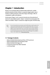
...8226; 3 x USB 2.0 Headers (Support 5 USB 2.0 ports) (Supports ESD Protection (ASRock Full Spike Protection)) • 1 x USB 3.0 Headers (Support 2 USB 3.0 ports) (Supports ESD Protection (ASRock Full Spike Protection)) BIOS Feature • AMI UEFI Legal BIOS with GUI support • Supports Plug and Play • ACPI 5.0 compliant wake up... • Microsoft® Windows® 10 64-bit * For the updated Windows® 10 driver, please visit ASRock's website for details: http://www.asrock.com • Linux: Ubuntu 16.10 / Fedora 25 Certifications • FCC, CE, WHQL • ErP/EuP...
...8226; 3 x USB 2.0 Headers (Support 5 USB 2.0 ports) (Supports ESD Protection (ASRock Full Spike Protection)) • 1 x USB 3.0 Headers (Support 2 USB 3.0 ports) (Supports ESD Protection (ASRock Full Spike Protection)) BIOS Feature • AMI UEFI Legal BIOS with GUI support • Supports Plug and Play • ACPI 5.0 compliant wake up... • Microsoft® Windows® 10 64-bit * For the updated Windows® 10 driver, please visit ASRock's website for details: http://www.asrock.com • Linux: Ubuntu 16.10 / Fedora 25 Certifications • FCC, CE, WHQL • ErP/EuP...

User Manual
Page 10
1.3 Motherboard Layout 1 2 3 CPU_FAN1 1 BIOS_PH BIOS ROM 1 CLRMOS1 CMOS Battery J3455M J3355M 4 PS2 Mouse PS2 Keyboard VGA1 DDR3_A1 (64 bit, 240-pin module) DDR3_B2 (64 bit, 240-pin module) DVI1 AT X P W R 1 Top: LINE IN Center: FRONT ...
1.3 Motherboard Layout 1 2 3 CPU_FAN1 1 BIOS_PH BIOS ROM 1 CLRMOS1 CMOS Battery J3455M J3355M 4 PS2 Mouse PS2 Keyboard VGA1 DDR3_A1 (64 bit, 240-pin module) DDR3_B2 (64 bit, 240-pin module) DVI1 AT X P W R 1 Top: LINE IN Center: FRONT ...
User Manual
Page 17
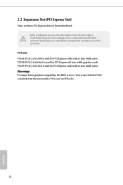
... the motherboard. 2.2 Expansion Slot (PCI Express Slot) There are three PCI Express slots on PCIe slot. 12 English Warning: To ensure better graphics compability, the BIOS is used for the card before you start the installation. Before installing an expansion card, please make necessary hardware settings for PCI Express cards with...
... the motherboard. 2.2 Expansion Slot (PCI Express Slot) There are three PCI Express slots on PCIe slot. 12 English Warning: To ensure better graphics compability, the BIOS is used for the card before you start the installation. Before installing an expansion card, please make necessary hardware settings for PCI Express cards with...
User Manual
Page 18
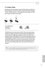
..., and then shut it down before you to short pin2 and pin3 on the pins, the jumper is removed. English 13 If you update the BIOS. To clear and reset the system parameters to default setup, please turn off the computer and unplug the power cord from the power supply.... J3455M J3355M 2.3 Jumpers Setup The illustration shows how jumpers are "Short" when a jumper cap is placed on the pins, the jumper is placed on CLRMOS1 for ...
..., and then shut it down before you to short pin2 and pin3 on the pins, the jumper is removed. English 13 If you update the BIOS. To clear and reset the system parameters to default setup, please turn off the computer and unplug the power cord from the power supply.... J3455M J3355M 2.3 Jumpers Setup The illustration shows how jumpers are "Short" when a jumper cap is placed on the pins, the jumper is placed on CLRMOS1 for ...
User Manual
Page 22
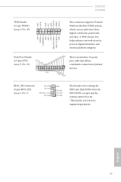
...(see p.5, No. 1) SPI_DQ0 SPI_CLK SPI Power (1.8V) SPI_DQ3 GND SPI_DQ1 SPI_CS# SPI_DQ2 1 This header is for writing the BIOS into flash ROM when the BIOS ROM corrupts and the system cannot boot up. *This header is an interface for factory engineering purpose. English 17 BIOS_PH Connector (9-... BUSY SPD3 SPD4 SPD5 ACK# SPD6 SPD7 1 GND SLIN# PINIT# ERROR# AFD# This is for print port cable that allows convenient connection of printer devices. J3455M J3355M GN D +3VS B LAD0 +3V LAD3 PCIRST # FRAM E PCICLK TPM Header (17-pin TPMS1) (see p.5, No. 18) GND SERIRQ # S_PWRDWN ...
...(see p.5, No. 1) SPI_DQ0 SPI_CLK SPI Power (1.8V) SPI_DQ3 GND SPI_DQ1 SPI_CS# SPI_DQ2 1 This header is for writing the BIOS into flash ROM when the BIOS ROM corrupts and the system cannot boot up. *This header is an interface for factory engineering purpose. English 17 BIOS_PH Connector (9-... BUSY SPD3 SPD4 SPD5 ACK# SPD6 SPD7 1 GND SLIN# PINIT# ERROR# AFD# This is for print port cable that allows convenient connection of printer devices. J3455M J3355M GN D +3VS B LAD0 +3V LAD3 PCIRST # FRAM E PCICLK TPM Header (17-pin TPMS1) (see p.5, No. 18) GND SERIRQ # S_PWRDWN ...
User Manual
Page 28
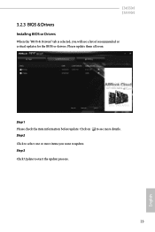
Step 3 Click Update to see a list of recommended or critical updates for the BIOS or drivers. Click to select one or more details. J3455M J3355M 3.2.3 BIOS & Drivers Installing BIOS or Drivers When the "BIOS & Drivers" tab is selected, you will see more items you want to update. Click on Step 2 to start the update process. 23 English Step 1 Please check the item information before update. Please update them all soon.
Step 3 Click Update to see a list of recommended or critical updates for the BIOS or drivers. Click to select one or more details. J3455M J3355M 3.2.3 BIOS & Drivers Installing BIOS or Drivers When the "BIOS & Drivers" tab is selected, you will see more items you want to update. Click on Step 2 to start the update process. 23 English Step 1 Please check the item information before update. Please update them all soon.
User Manual
Page 43
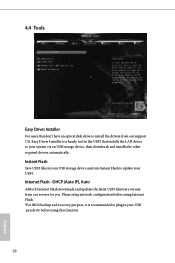
... files in your USB pen drive before using this function. 38 English Internet Flash - Please setup network configuration before using Internet Flash. *For BIOS backup and recovery purpose, it is a handy tool in the UEFI that installs the LAN driver to your system via an USB storage device,... then downloads and installs the other required drivers automatically. DHCP (Auto IP), Auto ASRock Internet Flash downloads and updates the latest UEFI firmware version from our support CD, Easy Driver Installer is recommended to plug in your USB ...
... files in your USB pen drive before using this function. 38 English Internet Flash - Please setup network configuration before using Internet Flash. *For BIOS backup and recovery purpose, it is a handy tool in the UEFI that installs the LAN driver to your system via an USB storage device,... then downloads and installs the other required drivers automatically. DHCP (Auto IP), Auto ASRock Internet Flash downloads and updates the latest UEFI firmware version from our support CD, Easy Driver Installer is recommended to plug in your USB ...

User Manual
Page 49
... option is set CSM to run those that support legacy option ROM only. You can change the Boot Mode setting from UEFI mode to Legacy BIOS mode by set to [Disabled] (UEFI mode). Launch Video OpROM Policy Select UEFI only to [Enabled]. If you are using Windows 8.1 64-bit and all...
... option is set CSM to run those that support legacy option ROM only. You can change the Boot Mode setting from UEFI mode to Legacy BIOS mode by set to [Disabled] (UEFI mode). Launch Video OpROM Policy Select UEFI only to [Enabled]. If you are using Windows 8.1 64-bit and all...


