User Manual
Page 4
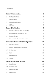
... 1 1.1 Package Contents 1 1.2 Specifications 2 1.3 Motherboard Layout 5 1.4 I/O Panel 7 Chapter 2 Installation 9 2.1 Installing Memory Modules (DIMM) 10 2.2 Expansion Slot (PCI Express Slot) 12 2.3 Jumpers Setup 13 2.4 Onboard Headers and Connectors 14 Chapter 3 Software and Utilities Operation 18 3.1 Installing Drivers 18 3.2 ASRock Live Update & APP Shop 19 3.2.1 UI Overview 19 3.2.2 Apps 20 3.2.3 BIOS & Drivers 23 3.2.4 Setting 24 Chapter 4 UEFI SETUP UTILITY 25 4.1 Introduction 25 4.1.1 UEFI Menu Bar 25 4.1.2 Navigation Keys 26 4.2 Main Screen 27
... 1 1.1 Package Contents 1 1.2 Specifications 2 1.3 Motherboard Layout 5 1.4 I/O Panel 7 Chapter 2 Installation 9 2.1 Installing Memory Modules (DIMM) 10 2.2 Expansion Slot (PCI Express Slot) 12 2.3 Jumpers Setup 13 2.4 Onboard Headers and Connectors 14 Chapter 3 Software and Utilities Operation 18 3.1 Installing Drivers 18 3.2 ASRock Live Update & APP Shop 19 3.2.1 UI Overview 19 3.2.2 Apps 20 3.2.3 BIOS & Drivers 23 3.2.4 Setting 24 Chapter 4 UEFI SETUP UTILITY 25 4.1 Introduction 25 4.1.1 UEFI Menu Bar 25 4.1.2 Navigation Keys 26 4.2 Main Screen 27
User Manual
Page 6
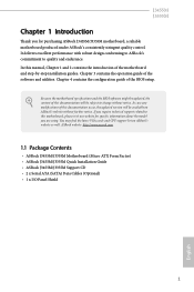
...; ASRock J3455M/J3355M Support CD • 2 x Serial ATA (SATA) Data Cables (Optional) • 1 x I/O Panel Shield 1 English If you require technical support related to this documentation occur, the updated version will be updated, the content of the BIOS setup. Because the motherboard specifications and the BIOS software might be subject to quality and endurance. In case any modifications of the motherboard and step-by-step installation guides. You may find the latest VGA cards and CPU support list...
...; ASRock J3455M/J3355M Support CD • 2 x Serial ATA (SATA) Data Cables (Optional) • 1 x I/O Panel Shield 1 English If you require technical support related to this documentation occur, the updated version will be updated, the content of the BIOS setup. Because the motherboard specifications and the BIOS software might be subject to quality and endurance. In case any modifications of the motherboard and step-by-step installation guides. You may find the latest VGA cards and CPU support list...

User Manual
Page 7
... @ 60Hz • Supports D-Sub with max. 1.2 Specifications Platform • Micro ATX Form Factor • Solid Capacitor design CPU • Intel® Quad-Core Processor J3455 (up to 2.3 GHz) (for J3455M) • Intel® Dual-Core Processor J3355 (up to 2048x1536 @ 60Hz • Supports Auto Lip Sync, xvYCC and HBR (High Bit Rate Audio) with HDMI Port (Compliant HDMI monitor is not supported Expansion Slot • 1 x PCI Express 2.0 x16 Slot (PCIE2: x1 mode) • 2 x PCI Express 2.0 x1 Slots Graphics • Integrated...
... @ 60Hz • Supports D-Sub with max. 1.2 Specifications Platform • Micro ATX Form Factor • Solid Capacitor design CPU • Intel® Quad-Core Processor J3455 (up to 2.3 GHz) (for J3455M) • Intel® Dual-Core Processor J3355 (up to 2048x1536 @ 60Hz • Supports Auto Lip Sync, xvYCC and HBR (High Bit Rate Audio) with HDMI Port (Compliant HDMI monitor is not supported Expansion Slot • 1 x PCI Express 2.0 x16 Slot (PCIE2: x1 mode) • 2 x PCI Express 2.0 x1 Slots Graphics • Integrated...
User Manual
Page 8
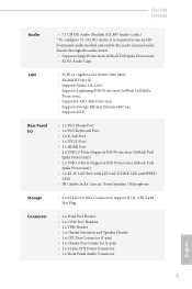
...8226; 2 x USB 3.0 Ports (Supports ESD Protection (ASRock Full Spike Protection)) • 1 x RJ-45 LAN Port with LED (ACT/LINK LED and SPEED LED) • HD Audio Jacks: Line in / Front Speaker / Microphone Storage • 2 x SATA3 6.0 Gb/s Connectors, support NCQ, AHCI and Hot Plug Connector • 1 x Print Port Header • 2 x COM Port Headers • 1 x TPM Header • 1 x Chassis Intrusion and Speaker Header • 1 x CPU Fan Connector (3-pin) • 1 x Chassis Fan Connector (3-pin) • 1 x 24 pin ATX Power Connector • 1 x Front Panel Audio Connector English 3
...8226; 2 x USB 3.0 Ports (Supports ESD Protection (ASRock Full Spike Protection)) • 1 x RJ-45 LAN Port with LED (ACT/LINK LED and SPEED LED) • HD Audio Jacks: Line in / Front Speaker / Microphone Storage • 2 x SATA3 6.0 Gb/s Connectors, support NCQ, AHCI and Hot Plug Connector • 1 x Print Port Header • 2 x COM Port Headers • 1 x TPM Header • 1 x Chassis Intrusion and Speaker Header • 1 x CPU Fan Connector (3-pin) • 1 x Chassis Fan Connector (3-pin) • 1 x 24 pin ATX Power Connector • 1 x Front Panel Audio Connector English 3
User Manual
Page 9
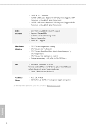
... Feature • AMI UEFI Legal BIOS with GUI support • Supports Plug and Play • ACPI 5.0 compliant wake up events • Supports jumperfree • SMBIOS 2.7 support Hardware Monitor • CPU/Chassis temperature sensing • CPU/Chassis Fan Tachometer • CPU/Chassis Quiet Fan (Auto adjust chassis fan speed by CPU temperature) • CPU/Chassis Fan multi-speed control • Voltage monitoring: +12V, +5V, +3.3V, CPU Vcore OS • Microsoft® Windows® 10 64-bit * For the updated Windows® 10 driver, please visit ASRock's website for details...
... Feature • AMI UEFI Legal BIOS with GUI support • Supports Plug and Play • ACPI 5.0 compliant wake up events • Supports jumperfree • SMBIOS 2.7 support Hardware Monitor • CPU/Chassis temperature sensing • CPU/Chassis Fan Tachometer • CPU/Chassis Quiet Fan (Auto adjust chassis fan speed by CPU temperature) • CPU/Chassis Fan multi-speed control • Voltage monitoring: +12V, +5V, +3.3V, CPU Vcore OS • Microsoft® Windows® 10 64-bit * For the updated Windows® 10 driver, please visit ASRock's website for details...
User Manual
Page 14
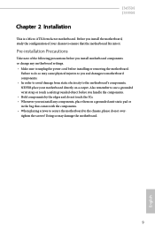
... injuries to you install the motherboard, study the configuration of the following precautions before you uninstall any motherboard settings. • Make sure to do not overtighten the screws! J3455M J3355M Chapter 2 Installation This is a Micro ATX form factor motherboard. Before you and damages to motherboard components. • In order to avoid damage from static electricity to the chassis, please do so...
... injuries to you install the motherboard, study the configuration of the following precautions before you uninstall any motherboard settings. • Make sure to do not overtighten the screws! J3455M J3355M Chapter 2 Installation This is a Micro ATX form factor motherboard. Before you and damages to motherboard components. • In order to avoid damage from static electricity to the chassis, please do so...
User Manual
Page 17
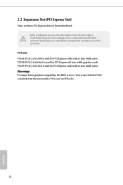
... the power supply is switched off or the power cord is unplugged. PCIe slot: PCIE1 (PCIe 2.0 x1 slot) is used for PCI Express x16 lane width graphics cards. PCIE2 (PCIe 2.0 x16 slot) is used for PCI Express cards with x1 lane width cards. PCIE3 (PCIe 2.0 x1 slot) is set to "boot from Onboard VGA" as default even the user install a VGA card on the motherboard. Warning: To ensure better graphics compability, the BIOS is used for the card before you start the installation. 2.2 Expansion Slot (PCI Express Slot) There are three PCI Express slots on PCIe slot...
... the power supply is switched off or the power cord is unplugged. PCIe slot: PCIE1 (PCIe 2.0 x1 slot) is used for PCI Express x16 lane width graphics cards. PCIE2 (PCIe 2.0 x16 slot) is used for PCI Express cards with x1 lane width cards. PCIE3 (PCIe 2.0 x1 slot) is set to "boot from Onboard VGA" as default even the user install a VGA card on the motherboard. Warning: To ensure better graphics compability, the BIOS is used for the card before you start the installation. 2.2 Expansion Slot (PCI Express Slot) There are three PCI Express slots on PCIe slot...
User Manual
Page 18
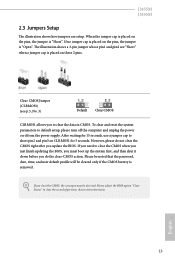
If you need to default setup, please turn off the computer and unplug the power cord from the power supply. J3455M J3355M 2.3 Jumpers Setup The illustration shows how jumpers are "Short" when a jumper cap is removed. When the jumper cap is placed on these 2 pins. To clear and reset the system parameters to clear the CMOS when you just finish updating the BIOS, you must boot up the system first, and then shut...
If you need to default setup, please turn off the computer and unplug the power cord from the power supply. J3455M J3355M 2.3 Jumpers Setup The illustration shows how jumpers are "Short" when a jumper cap is removed. When the jumper cap is placed on these 2 pins. To clear and reset the system parameters to clear the CMOS when you just finish updating the BIOS, you must boot up the system first, and then shut...

User Manual
Page 19
... (Hard Drive Activity LED): Connect to this header, make sure the wire assignments and the pin assignments are NOT jumpers. The LED keeps blinking when the system is reading or writing data. A front panel module mainly consists of power switch, reset switch, power LED, hard drive activity LED, speaker and etc. You may differ by chassis. The LED is on the chassis to this header according to the power status indicator on the chassis front panel. 2.4 Onboard Headers and Connectors Onboard headers and connectors...
... (Hard Drive Activity LED): Connect to this header, make sure the wire assignments and the pin assignments are NOT jumpers. The LED keeps blinking when the system is reading or writing data. A front panel module mainly consists of power switch, reset switch, power LED, hard drive activity LED, speaker and etc. You may differ by chassis. The LED is on the chassis to this header according to the power status indicator on the chassis front panel. 2.4 Onboard Headers and Connectors Onboard headers and connectors...

User Manual
Page 21
... panel audio header by the steps below: A. Chassis Fan Connector (3-pin CHA_FAN1) (see p.5, No. 17) RRXD1 DDTR#1 DDSR#1 CCTS#1 1 RRI#1 RRTS#1 GND TTXD1 DDCD#1 Please connect the CPU fan cable to the connector and match the black wire to the ground pin. These two COM headers support serial port modules. 16 English 1. MIC_RET and OUT_RET are for the AC'97 audio panel. E. B. If you use a 20-pin ATX power supply, please plug it to install your system. 2. CPU Fan Connector (3-pin...
... panel audio header by the steps below: A. Chassis Fan Connector (3-pin CHA_FAN1) (see p.5, No. 17) RRXD1 DDTR#1 DDSR#1 CCTS#1 1 RRI#1 RRTS#1 GND TTXD1 DDCD#1 Please connect the CPU fan cable to the connector and match the black wire to the ground pin. These two COM headers support serial port modules. 16 English 1. MIC_RET and OUT_RET are for the AC'97 audio panel. E. B. If you use a 20-pin ATX power supply, please plug it to install your system. 2. CPU Fan Connector (3-pin...
User Manual
Page 23
... To improve Windows 7 compatibility, please download and install the following hot fix provided by Microsoft. Utilities Menu The Utilities Menu shows the application software that enhance the motherboard's features. If the Main Menu does not appear automatically, locate and double click on the support CD driver page. Drivers Menu The drivers compatible to your system will be auto-detected and listed on the file "ASRSETUP.EXE" in your CD-ROM drive. Click on a specific item...
... To improve Windows 7 compatibility, please download and install the following hot fix provided by Microsoft. Utilities Menu The Utilities Menu shows the application software that enhance the motherboard's features. If the Main Menu does not appear automatically, locate and double click on the support CD driver page. Drivers Menu The drivers compatible to your system will be auto-detected and listed on the file "ASRSETUP.EXE" in your CD-ROM drive. Click on a specific item...

User Manual
Page 24
... easily install various apps and support utilities, such as USB Key, XFast LAN, XFast RAM and more . 19 English on the image to perform job-related tasks. Double-click utility. Click on your ASRock computer. Hot News: The hot news section displays the various latest news. Information Panel: The information panel in the center displays data about the currently selected category and allows users...
... easily install various apps and support utilities, such as USB Key, XFast LAN, XFast RAM and more . 19 English on the image to perform job-related tasks. Double-click utility. Click on your ASRock computer. Hot News: The hot news section displays the various latest news. Information Panel: The information panel in the center displays data about the currently selected category and allows users...
User Manual
Page 30
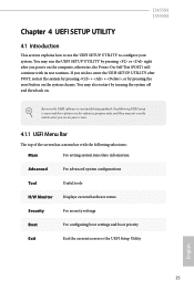
... the UEFI software is constantly being updated, the following selections: Main For setting system time/date information Advanced For advanced system configurations Tool Useful tools H/W Monitor Displays current hardware status Security For security settings Boot For configuring boot settings and boot priority Exit Exit the current screen or the UEFI Setup Utility English 25 If you wish to configure your screen. 4.1.1 UEFI Menu Bar The top of the screen has a menu bar with the following UEFI setup screens...
... the UEFI software is constantly being updated, the following selections: Main For setting system time/date information Advanced For advanced system configurations Tool Useful tools H/W Monitor Displays current hardware status Security For security settings Boot For configuring boot settings and boot priority Exit Exit the current screen or the UEFI Setup Utility English 25 If you wish to configure your screen. 4.1.1 UEFI Menu Bar The top of the screen has a menu bar with the following UEFI setup screens...

User Manual
Page 35
... DRAM Frequency If [Auto] is [Auto]. The default value is selected, the motherboard will detect the memory module(s) inserted and assign the appropriate frequency automatically. Set to Auto to enable onboard HD audio and automatically disable it when a sound card is set to [Onboard] (boot from onboard VGA). Primary Graphics Adapter Select a primary VGA. *To ensure better graphics compatibility, the default is installed. Share Memory Configure the size of memory that is allocated to configure DRAM Voltage. DRAM Voltage (1.50V) Use this to the integrated graphics processor...
... DRAM Frequency If [Auto] is [Auto]. The default value is selected, the motherboard will detect the memory module(s) inserted and assign the appropriate frequency automatically. Set to Auto to enable onboard HD audio and automatically disable it when a sound card is set to [Onboard] (boot from onboard VGA). Primary Graphics Adapter Select a primary VGA. *To ensure better graphics compatibility, the default is installed. Share Memory Configure the size of memory that is allocated to configure DRAM Voltage. DRAM Voltage (1.50V) Use this to the integrated graphics processor...

User Manual
Page 36
.... Restore on . PCIE2 Link Speed Select the link speed for PCIE1. If [Power On] is shut down. PCIE3 Link Speed Select the link speed for power saving when the computer is selected, the system will be switched off when the power recovers. Good Night LED By enabling Good Night LED, the Power LEDs will start to boot up when the power recovers. J3455M J3355M Onboard LAN Enable or disable the onboard network interface controller.
.... Restore on . PCIE2 Link Speed Select the link speed for PCIE1. If [Power On] is shut down. PCIE3 Link Speed Select the link speed for power saving when the computer is selected, the system will be switched off when the power recovers. Good Night LED By enabling Good Night LED, the Power LEDs will start to boot up when the power recovers. J3455M J3355M Onboard LAN Enable or disable the onboard network interface controller.

User Manual
Page 38
Serial Port 2 Enable or disable the Serial port 2. Device Mode Select the device mode according to your connected device. 33 English Serial Port Address Select the address of the Parallel port. Change Settings Select the address of the Serial port. Parallel Port Enable or disable the Parallel port. 4.3.4 Super IO Configuration J3455M J3355M Serial Port 1 Enable or disable the Serial port 1. Serial Port Address Select the address of the Serial port.
Serial Port 2 Enable or disable the Serial port 2. Device Mode Select the device mode according to your connected device. 33 English Serial Port Address Select the address of the Parallel port. Change Settings Select the address of the Serial port. Parallel Port Enable or disable the Parallel port. 4.3.4 Super IO Configuration J3455M J3355M Serial Port 1 Enable or disable the Serial port 1. Serial Port Address Select the address of the Serial port.
User Manual
Page 43
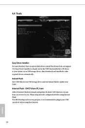
... Flash - Instant Flash Save UEFI files in your UEFI. Please setup network configuration before using Internet Flash. *For BIOS backup and recovery purpose, it is a handy tool in the UEFI that installs the LAN driver to plug in your USB storage device and run Instant Flash to update your USB pen drive before using this function. 38 English DHCP (Auto IP), Auto ASRock Internet Flash downloads and updates the latest UEFI firmware version from our support CD, Easy Driver Installer is recommended to your system via an USB storage device...
... Flash - Instant Flash Save UEFI files in your UEFI. Please setup network configuration before using Internet Flash. *For BIOS backup and recovery purpose, it is a handy tool in the UEFI that installs the LAN driver to plug in your USB storage device and run Instant Flash to update your USB pen drive before using this function. 38 English DHCP (Auto IP), Auto ASRock Internet Flash downloads and updates the latest UEFI firmware version from our support CD, Easy Driver Installer is recommended to your system via an USB storage device...

User Manual
Page 44
UEFI Download Server Select a server to configure internet connection settings for Internet Flash. J3455M J3355M Internet Setting Enable or disable sound effects in the setup utility. Network Configuration Use this to download the UEFI firmware. English 39
UEFI Download Server Select a server to configure internet connection settings for Internet Flash. J3455M J3355M Internet Setting Enable or disable sound effects in the setup utility. Network Configuration Use this to download the UEFI firmware. English 39

User Manual
Page 45
The default value is [Full On]. Chassis Fan 1 Setting This allows you to set CPU fan 1's speed. 4.5 Hardware Health Event Monitoring Screen This section allows you to set chassis fan 1's speed. Case Open Feature Enable or disable Case Open Feature to monitor the status of the hardware on your system, including the parameters of the CPU temperature, motherboard temperature, fan speed and voltage. The default value is [Full On]. Configuration options: [Full On], [Automatic Mode] and [Manual]. Configuration options: [Full On] and [Automatic Mode]. CPU Fan 1 Setting This...
The default value is [Full On]. Chassis Fan 1 Setting This allows you to set CPU fan 1's speed. 4.5 Hardware Health Event Monitoring Screen This section allows you to set chassis fan 1's speed. Case Open Feature Enable or disable Case Open Feature to monitor the status of the hardware on your system, including the parameters of the CPU temperature, motherboard temperature, fan speed and voltage. The default value is [Full On]. Configuration options: [Full On], [Automatic Mode] and [Manual]. Configuration options: [Full On] and [Automatic Mode]. CPU Fan 1 Setting This...
User Manual
Page 46
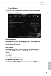
... user password. Supervisor Password Set or change the password for the administrator account. User Password Set or change the password for the user account. J3455M J3355M 4.6 Security Screen In this option to use discrete TPM Module. 41 English Leave it blank and press enter to change the settings in the UEFI Setup Utility. Secure Boot Enable to change the settings in the UEFI Setup Utility. Users are unable to remove the password. Only the administrator has authority to support Windows 8.1 Secure Boot. Intel(R) Platform Trust Technology Enable/disable...
... user password. Supervisor Password Set or change the password for the administrator account. User Password Set or change the password for the user account. J3455M J3355M 4.6 Security Screen In this option to use discrete TPM Module. 41 English Leave it blank and press enter to change the settings in the UEFI Setup Utility. Secure Boot Enable to change the settings in the UEFI Setup Utility. Users are unable to remove the password. Only the administrator has authority to support Windows 8.1 Secure Boot. Intel(R) Platform Trust Technology Enable/disable...


