
User Manual
Page 4
... 1.2 Specifications 2 1.3 Motherboard Layout 5 1.4 I/O Panel 7 Chapter 2 Installation 9 2.1 Installing Memory Modules (SO-DIMM) 10 2.2 Expansion Slot (PCI Express Slot) 12 2.3 Jumpers Setup 13 2.4 Onboard Headers and Connectors 14 2.5 M.2 WiFi/BT Module Installation Guide 18 Chapter 3 Software and Utilities Operation 20 3.1 Installing Drivers 20 3.2 ASRock Live Update & APP Shop 21 3.2.1 UI Overview 21 3.2.2 Apps 22 3.2.3 BIOS & Drivers 25 3.2.4 Setting 26 Chapter 4 UEFI SETUP UTILITY 27 4.1 Introduction 27 4.1.1 UEFI Menu Bar 27 4.1.2 Navigation Keys 28
... 1.2 Specifications 2 1.3 Motherboard Layout 5 1.4 I/O Panel 7 Chapter 2 Installation 9 2.1 Installing Memory Modules (SO-DIMM) 10 2.2 Expansion Slot (PCI Express Slot) 12 2.3 Jumpers Setup 13 2.4 Onboard Headers and Connectors 14 2.5 M.2 WiFi/BT Module Installation Guide 18 Chapter 3 Software and Utilities Operation 20 3.1 Installing Drivers 20 3.2 ASRock Live Update & APP Shop 21 3.2.1 UI Overview 21 3.2.2 Apps 22 3.2.3 BIOS & Drivers 25 3.2.4 Setting 26 Chapter 4 UEFI SETUP UTILITY 27 4.1 Introduction 27 4.1.1 UEFI Menu Bar 27 4.1.2 Navigation Keys 28
User Manual
Page 6
...; ASRock J4205-ITX/J3455-ITX Motherboard (Mini-ITX Form Factor) • ASRock J4205-ITX/J3455-ITX Quick Installation Guide • ASRock J4205-ITX/J3455-ITX Support CD • 2 x Serial ATA (SATA) Data Cables (Optional) • 1 x I/O Panel Shield • 1 x WiFi Module Screw (Optional) 1 English Because the motherboard specifications and the BIOS software might be updated, the content of this documentation will be subject to change without further notice. You may find the latest VGA cards and CPU support list on ASRock's website without notice. In case any...
...; ASRock J4205-ITX/J3455-ITX Motherboard (Mini-ITX Form Factor) • ASRock J4205-ITX/J3455-ITX Quick Installation Guide • ASRock J4205-ITX/J3455-ITX Support CD • 2 x Serial ATA (SATA) Data Cables (Optional) • 1 x I/O Panel Shield • 1 x WiFi Module Screw (Optional) 1 English Because the motherboard specifications and the BIOS software might be updated, the content of this documentation will be subject to change without further notice. You may find the latest VGA cards and CPU support list on ASRock's website without notice. In case any...

User Manual
Page 7
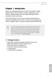
... HDMI Ports 2 English capacity of system memory: 16GB Expansion Slot • 1 x PCI Express 2.0 x1 Slot • 1 x M.2 Socket (Key E), supports type 2230 WiFi/BT module Graphics • Integrated Intel® HD Graphics 505: 18 EUs inside (Up to 800MHz) (for J4205-ITX) • Integrated Intel® HD Graphics 500: 12 EUs inside (Up to 750MHz) (for J3455-ITX) Memory • Dual Channel DDR3/DDR3L Memory Technology • 2 x DDR3/DDR3L SO-DIMM Slots * 2GB DRAM is...
... HDMI Ports 2 English capacity of system memory: 16GB Expansion Slot • 1 x PCI Express 2.0 x1 Slot • 1 x M.2 Socket (Key E), supports type 2230 WiFi/BT module Graphics • Integrated Intel® HD Graphics 505: 18 EUs inside (Up to 800MHz) (for J4205-ITX) • Integrated Intel® HD Graphics 500: 12 EUs inside (Up to 750MHz) (for J3455-ITX) Memory • Dual Channel DDR3/DDR3L Memory Technology • 2 x DDR3/DDR3L SO-DIMM Slots * 2GB DRAM is...
User Manual
Page 8
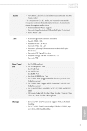
...; Supports PXE Rear Panel I/O • 1 x PS/2 Mouse Port • 1 x PS/2 Keyboard Port • 1 x D-Sub Port • 1 x DVI-D Port • 1 x HDMI Port • 1 x Optical SPDIF Out Port • 2 x USB 2.0 Ports (Supports ESD Protection (ASRock Full Spike Protection)) • 2 x USB 3.0 Ports (Supports ESD Protection (ASRock Full Spike Protection)) • 1 x RJ-45 LAN Port with LED (ACT/LINK LED and SPEED LED) • HD Audio Jacks: Side Speaker / Rear Speaker / Central / Bass / Line in / Front Speaker / Microphone Storage • 2 x SATA3 6.0 Gb/s Connectors, support NCQ, AHCI...
...; Supports PXE Rear Panel I/O • 1 x PS/2 Mouse Port • 1 x PS/2 Keyboard Port • 1 x D-Sub Port • 1 x DVI-D Port • 1 x HDMI Port • 1 x Optical SPDIF Out Port • 2 x USB 2.0 Ports (Supports ESD Protection (ASRock Full Spike Protection)) • 2 x USB 3.0 Ports (Supports ESD Protection (ASRock Full Spike Protection)) • 1 x RJ-45 LAN Port with LED (ACT/LINK LED and SPEED LED) • HD Audio Jacks: Side Speaker / Rear Speaker / Central / Bass / Line in / Front Speaker / Microphone Storage • 2 x SATA3 6.0 Gb/s Connectors, support NCQ, AHCI...
User Manual
Page 9
... Speaker Header • 1 x CPU Fan Connector (3-pin) • 1 x Chassis Fan Connector (3-pin) • 1 x 24 pin ATX Power Connector • 1 x Front Panel Audio Connector • 2 x USB 2.0 Headers (Support 3 USB 2.0 ports) (Supports ESD Protection (ASRock Full Spike Protection)) • 1 x USB 3.0 Header (Supports 2 USB 3.0 ports) (Supports ESD Protection (ASRock Full Spike Protection)) * USB3_0_1 is required) * For detailed product information, please visit our website: http://www.asrock.com English 4 BIOS Feature • AMI UEFI Legal BIOS with GUI support • Supports Plug...
... Speaker Header • 1 x CPU Fan Connector (3-pin) • 1 x Chassis Fan Connector (3-pin) • 1 x 24 pin ATX Power Connector • 1 x Front Panel Audio Connector • 2 x USB 2.0 Headers (Support 3 USB 2.0 ports) (Supports ESD Protection (ASRock Full Spike Protection)) • 1 x USB 3.0 Header (Supports 2 USB 3.0 ports) (Supports ESD Protection (ASRock Full Spike Protection)) * USB3_0_1 is required) * For detailed product information, please visit our website: http://www.asrock.com English 4 BIOS Feature • AMI UEFI Legal BIOS with GUI support • Supports Plug...
User Manual
Page 14
... your chassis to ensure that comes with the components. • When placing screws to secure the motherboard to you uninstall any motherboard settings. • Make sure to unplug the power cord before you install the motherboard, study the configuration of the following precautions before installing or removing the motherboard. Failure to do so may damage the motherboard. 9 English Before you install motherboard components or change any...
... your chassis to ensure that comes with the components. • When placing screws to secure the motherboard to you uninstall any motherboard settings. • Make sure to unplug the power cord before you install the motherboard, study the configuration of the following precautions before installing or removing the motherboard. Failure to do so may damage the motherboard. 9 English Before you install motherboard components or change any...

User Manual
Page 17
... necessary hardware settings for PCI Express cards with x1 lane width cards. Warning: To ensure better graphics compability, the BIOS is 1 PCI Express slot on PCIe slot. 12 English Please read the documentation of the expansion card and make sure that the power supply is switched off or the power cord is used for the card before you start the installation. 2.2 Expansion Slot (PCI Express Slot) There is set to "boot from Onboard VGA" as default even the user install a VGA card on the motherboard.
... necessary hardware settings for PCI Express cards with x1 lane width cards. Warning: To ensure better graphics compability, the BIOS is 1 PCI Express slot on PCIe slot. 12 English Please read the documentation of the expansion card and make sure that the power supply is switched off or the power cord is used for the card before you start the installation. 2.2 Expansion Slot (PCI Express Slot) There is set to "boot from Onboard VGA" as default even the user install a VGA card on the motherboard.
User Manual
Page 18
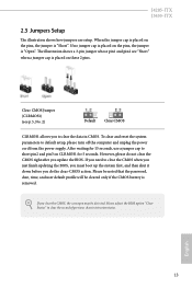
... need to default setup, please turn off the computer and unplug the power cord from the power supply. However, please do the clear-CMOS action. English 13 Please be noted that the password, date, time, and user default profile will be detected. J4205-ITX J3455-ITX 2.3 Jumpers Setup The illustration shows how jumpers are "Short" when a jumper cap is "Short". Please adjust the BIOS option "Clear Status" to clear the record of previous chassis intrusion...
... need to default setup, please turn off the computer and unplug the power cord from the power supply. However, please do the clear-CMOS action. English 13 Please be noted that the password, date, time, and user default profile will be detected. J4205-ITX J3455-ITX 2.3 Jumpers Setup The illustration shows how jumpers are "Short" when a jumper cap is "Short". Please adjust the BIOS option "Clear Status" to clear the record of previous chassis intrusion...

User Manual
Page 21
1. If you use a 20-pin ATX power supply, please plug it to the ground pin. C. MIC_RET and OUT_RET are for the AC'97 audio panel. Chassis Fan Connector (3-pin CHA_FAN1) (see p.5, No. 3) 16 12 24 1 13 This motherboard provides a 24-pin ATX power connector. A TPM system also helps enhance network security, protects digital identities, and ensures platform integrity. ATX Power Connector (24-pin ATXPWR1) (see p.5, No. 4) TPM Header (17-pin TPMS1) (see p.5, No. 10) GND FAN_VOLTAGE...
1. If you use a 20-pin ATX power supply, please plug it to the ground pin. C. MIC_RET and OUT_RET are for the AC'97 audio panel. Chassis Fan Connector (3-pin CHA_FAN1) (see p.5, No. 3) 16 12 24 1 13 This motherboard provides a 24-pin ATX power connector. A TPM system also helps enhance network security, protects digital identities, and ensures platform integrity. ATX Power Connector (24-pin ATXPWR1) (see p.5, No. 4) TPM Header (17-pin TPMS1) (see p.5, No. 10) GND FAN_VOLTAGE...

User Manual
Page 23
... M.2 slot. The M.2 Socket (Key E) supports type 2230 WiFi/BT module. * The M.2 socket does not support SATA M.2 SSDs. 2.5 M.2 WiFi/BT Module Installation Guide The M.2, also known as the Next Generation Form Factor (NGFF), is a small size and versatile card edge connector that aims to be aware that the module only fits in one orientation. Module Type: Type2230 PCB Length: 3cm Step 2 Find the nut location to replace...
... M.2 slot. The M.2 Socket (Key E) supports type 2230 WiFi/BT module. * The M.2 socket does not support SATA M.2 SSDs. 2.5 M.2 WiFi/BT Module Installation Guide The M.2, also known as the Next Generation Form Factor (NGFF), is a small size and versatile card edge connector that aims to be aware that the module only fits in one orientation. Module Type: Type2230 PCB Length: 3cm Step 2 Find the nut location to replace...
User Manual
Page 25
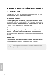
... 3 Software and Utilities Operation 3.1 Installing Drivers The Support CD that comes with the motherboard contains necessary drivers and useful utilities that the motherboard supports. If the Main Menu does not appear automatically, locate and double click on the file "ASRSETUP.EXE" in your CD-ROM drive. Please click Install All or follow the installation wizard to install those required drivers. Utilities Menu The Utilities Menu shows the application software that enhance the motherboard's features. To improve Windows 7 compatibility, please download...
... 3 Software and Utilities Operation 3.1 Installing Drivers The Support CD that comes with the motherboard contains necessary drivers and useful utilities that the motherboard supports. If the Main Menu does not appear automatically, locate and double click on the file "ASRSETUP.EXE" in your CD-ROM drive. Please click Install All or follow the installation wizard to install those required drivers. Utilities Menu The Utilities Menu shows the application software that enhance the motherboard's features. To improve Windows 7 compatibility, please download...
User Manual
Page 26
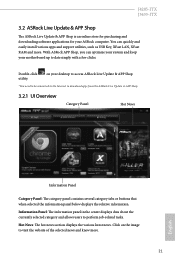
... desktop to access ASRock Live Update & APP Shop *You need to be connected to the Internet to perform job-related tasks. With ASRock APP Shop, you can quickly and easily install various apps and support utilities, such as USB Key, XFast LAN, XFast RAM and more . 21 English J4205-ITX J3455-ITX 3.2 ASRock Live Update & APP Shop The ASRock Live Update & APP Shop is an online store for purchasing and downloading software...
... desktop to access ASRock Live Update & APP Shop *You need to be connected to the Internet to perform job-related tasks. With ASRock APP Shop, you can quickly and easily install various apps and support utilities, such as USB Key, XFast LAN, XFast RAM and more . 21 English J4205-ITX J3455-ITX 3.2 ASRock Live Update & APP Shop The ASRock Live Update & APP Shop is an online store for purchasing and downloading software...
User Manual
Page 32
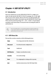
... selections: Main For setting system time/date information Advanced For advanced system configurations Tool Useful tools H/W Monitor Displays current hardware status Security For security settings Boot For configuring boot settings and boot priority Exit Exit the current screen or the UEFI Setup Utility English 27 You may not exactly match what you power on . J4205-ITX J3455-ITX Chapter 4 UEFI SETUP UTILITY 4.1 Introduction This section explains how to use the UEFI SETUP UTILITY to enter the UEFI SETUP UTILITY after you...
... selections: Main For setting system time/date information Advanced For advanced system configurations Tool Useful tools H/W Monitor Displays current hardware status Security For security settings Boot For configuring boot settings and boot priority Exit Exit the current screen or the UEFI Setup Utility English 27 You may not exactly match what you power on . J4205-ITX J3455-ITX Chapter 4 UEFI SETUP UTILITY 4.1 Introduction This section explains how to use the UEFI SETUP UTILITY to enter the UEFI SETUP UTILITY after you...

User Manual
Page 37
4.3.2 Chipset Configuration DRAM Frequency If [Auto] is [Auto]. DRAM Voltage (1.35V) Use this to enable onboard HD audio and automatically disable it when a sound card is installed. 32 English The default value is selected, the motherboard will detect the memory module(s) inserted and assign the appropriate frequency automatically. Share Memory Configure the size of memory that is set to the integrated graphics processor when the system boots up. Onboard HD Audio Enable/disable onboard HD audio. Primary Graphics Adapter Select a primary VGA. *To ensure better graphics compatibility...
4.3.2 Chipset Configuration DRAM Frequency If [Auto] is [Auto]. DRAM Voltage (1.35V) Use this to enable onboard HD audio and automatically disable it when a sound card is installed. 32 English The default value is selected, the motherboard will detect the memory module(s) inserted and assign the appropriate frequency automatically. Share Memory Configure the size of memory that is set to the integrated graphics processor when the system boots up. Onboard HD Audio Enable/disable onboard HD audio. Primary Graphics Adapter Select a primary VGA. *To ensure better graphics compatibility...
User Manual
Page 38
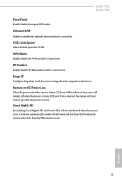
... enters into Standby/Hibernation mode. 33 English If [Power On] is shut down. Good Night LED By enabling Good Night LED, the Power LEDs will also automatically switch off when the power recovers. It will be switched off when the system is selected, the power will start to boot up when the power recovers. Restore on . Onboard LAN Enable or disable the onboard network interface controller. BT Enabled Enable/disable the Bluetooth module's connectivity. J4205-ITX J3455-ITX Front Panel Enable/disable...
... enters into Standby/Hibernation mode. 33 English If [Power On] is shut down. Good Night LED By enabling Good Night LED, the Power LEDs will also automatically switch off when the power recovers. It will be switched off when the system is selected, the power will start to boot up when the power recovers. Restore on . Onboard LAN Enable or disable the onboard network interface controller. BT Enabled Enable/disable the Bluetooth module's connectivity. J4205-ITX J3455-ITX Front Panel Enable/disable...

User Manual
Page 40
Serial Port Address Select the address of the Serial port. 35 English 4.3.4 Super IO Configuration J4205-ITX J3455-ITX Serial Port 1 Enable or disable the Serial port 1.
Serial Port Address Select the address of the Serial port. 35 English 4.3.4 Super IO Configuration J4205-ITX J3455-ITX Serial Port 1 Enable or disable the Serial port 1.
User Manual
Page 45
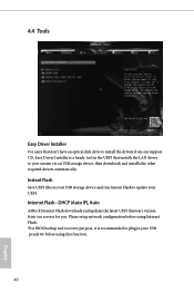
... setup network configuration before using Internet Flash. *For BIOS backup and recovery purpose, it is recommended to your system via an USB storage device, then downloads and installs the other required drivers automatically. 4.4 Tools Easy Driver Installer For users that don't have an optical disk drive to install the drivers from our servers for you. DHCP (Auto IP), Auto ASRock Internet Flash downloads and updates the latest UEFI firmware version from our support CD, Easy Driver Installer is a handy tool in the UEFI...
... setup network configuration before using Internet Flash. *For BIOS backup and recovery purpose, it is recommended to your system via an USB storage device, then downloads and installs the other required drivers automatically. 4.4 Tools Easy Driver Installer For users that don't have an optical disk drive to install the drivers from our servers for you. DHCP (Auto IP), Auto ASRock Internet Flash downloads and updates the latest UEFI firmware version from our support CD, Easy Driver Installer is a handy tool in the UEFI...

User Manual
Page 46
English 41 UEFI Download Server Select a server to configure internet connection settings for Internet Flash. Network Configuration Use this to download the UEFI firmware. J4205-ITX J3455-ITX Internet Setting Enable or disable sound effects in the setup utility.
English 41 UEFI Download Server Select a server to configure internet connection settings for Internet Flash. Network Configuration Use this to download the UEFI firmware. J4205-ITX J3455-ITX Internet Setting Enable or disable sound effects in the setup utility.

User Manual
Page 47
... Mode]. Configuration options: [Full On], [Automatic Mode] and [Manual]. The default value is [Full On]. The default value is [Full On]. Case Open Feature Enable or disable Case Open Feature to detect whether the chassis cover has been removed. 42 English CPU Fan 1 Setting This allows you to set chassis fan 1's speed. Chassis Fan 1 Setting This allows you to monitor the status of the hardware on your system, including the parameters of the CPU temperature, motherboard temperature, fan speed and voltage...
... Mode]. Configuration options: [Full On], [Automatic Mode] and [Manual]. The default value is [Full On]. The default value is [Full On]. Case Open Feature Enable or disable Case Open Feature to detect whether the chassis cover has been removed. 42 English CPU Fan 1 Setting This allows you to set chassis fan 1's speed. Chassis Fan 1 Setting This allows you to monitor the status of the hardware on your system, including the parameters of the CPU temperature, motherboard temperature, fan speed and voltage...
User Manual
Page 48
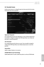
... Boot Enable to use discrete TPM Module. 43 English Intel(R) Platform Trust Technology Enable/disable Intel PTT in the UEFI Setup Utility. Leave it blank and press enter to remove the password. J4205-ITX J3455-ITX 4.6 Security Screen In this option to support Windows 8.1 Secure Boot. You may set or change the supervisor/user password for the system. Disable this section you may also clear the user password. Supervisor Password Set or change the settings in the UEFI Setup Utility. Leave it blank and press enter...
... Boot Enable to use discrete TPM Module. 43 English Intel(R) Platform Trust Technology Enable/disable Intel PTT in the UEFI Setup Utility. Leave it blank and press enter to remove the password. J4205-ITX J3455-ITX 4.6 Security Screen In this option to support Windows 8.1 Secure Boot. You may set or change the supervisor/user password for the system. Disable this section you may also clear the user password. Supervisor Password Set or change the settings in the UEFI Setup Utility. Leave it blank and press enter...


