

User Manual
Page 4
... Contents 1 1.2 Specifications 2 1.3 Motherboard Layout 5 1.4 I/O Panel 7 Chapter 2 Installation 9 2.1 Installing Memory Modules (DIMM) 10 2.2 Expansion Slots (PCI Express Slots) 12 2.3 Jumpers Setup 13 2.4 Onboard Headers and Connectors 14 Chapter 3 Software and Utilities Operation 18 3.1 Installing Drivers 18 3.2 ASRock Live Update & APP Shop 19 3.2.1 UI Overview 19 3.2.2 Apps 20 3.2.3 BIOS & Drivers 23 3.2.4 Setting 24 3.3 Enabling USB Ports for Windows® 7 Installation 25 Chapter 4 UEFI SETUP UTILITY 28 4.1 Introduction 28 4.1.1 UEFI Menu Bar 28...
... Contents 1 1.2 Specifications 2 1.3 Motherboard Layout 5 1.4 I/O Panel 7 Chapter 2 Installation 9 2.1 Installing Memory Modules (DIMM) 10 2.2 Expansion Slots (PCI Express Slots) 12 2.3 Jumpers Setup 13 2.4 Onboard Headers and Connectors 14 Chapter 3 Software and Utilities Operation 18 3.1 Installing Drivers 18 3.2 ASRock Live Update & APP Shop 19 3.2.1 UI Overview 19 3.2.2 Apps 20 3.2.3 BIOS & Drivers 23 3.2.4 Setting 24 3.3 Enabling USB Ports for Windows® 7 Installation 25 Chapter 4 UEFI SETUP UTILITY 28 4.1 Introduction 28 4.1.1 UEFI Menu Bar 28...

User Manual
Page 6
...about the model you for purchasing ASRock J3710M / J3160M / J3060M motherboard, a reliable motherboard produced under ASRock's consistently stringent quality control. Chapter 1 Introduction J3710M J3160M J3060M Thank you are using. Chapter 3 contains the operation guide of the BIOS setup. ASRock website http://www.asrock.com. 1.1 Package Contents • ASRock J3710M / J3160M / J3060M Motherboard (Micro ATX Form Factor) • ASRock J3710M / J3160M / J3060M Quick Installation Guide • ASRock J3710M / J3160M / J3060M Support CD • 2 x Serial ATA (SATA) Data Cables (Optional...
...about the model you for purchasing ASRock J3710M / J3160M / J3060M motherboard, a reliable motherboard produced under ASRock's consistently stringent quality control. Chapter 1 Introduction J3710M J3160M J3060M Thank you are using. Chapter 3 contains the operation guide of the BIOS setup. ASRock website http://www.asrock.com. 1.1 Package Contents • ASRock J3710M / J3160M / J3060M Motherboard (Micro ATX Form Factor) • ASRock J3710M / J3160M / J3060M Quick Installation Guide • ASRock J3710M / J3160M / J3060M Support CD • 2 x Serial ATA (SATA) Data Cables (Optional...

User Manual
Page 7
... @ 60Hz • Supports D-Sub with max. resolution up to 1920x1200 @ 60Hz • Supports Auto Lip Sync, xvYCC and HBR (High Bit Rate Audio) with max. resolution up to 2.48 GHz) (for J3060M) Memory • Dual Channel DDR3/DDR3L Memory Technology • 2 x DDR3/DDR3L DIMM Slots • Supports DDR3/DDR3L 1600/1066 non-ECC, un-buffered memory • Max. Expansion Slot • 1 x PCI Express 2.0 x16 Slot (PCIE2 @ x1 mode) • 2 x PCI Express 2.0 x1 Slots Graphics • Integrated Intel...
... @ 60Hz • Supports D-Sub with max. resolution up to 1920x1200 @ 60Hz • Supports Auto Lip Sync, xvYCC and HBR (High Bit Rate Audio) with max. resolution up to 2.48 GHz) (for J3060M) Memory • Dual Channel DDR3/DDR3L Memory Technology • 2 x DDR3/DDR3L DIMM Slots • Supports DDR3/DDR3L 1600/1066 non-ECC, un-buffered memory • Max. Expansion Slot • 1 x PCI Express 2.0 x16 Slot (PCIE2 @ x1 mode) • 2 x PCI Express 2.0 x1 Slots Graphics • Integrated Intel...
User Manual
Page 8
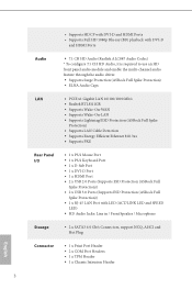
... Port • 1 x PS/2 Keyboard Port • 1 x D-Sub Port • 1 x DVI-D Port • 1 x HDMI Port • 2 x USB 2.0 Ports (Supports ESD Protection (ASRock Full Spike Protection)) • 2 x USB 3.0 Ports (Supports ESD Protection (ASRock Full Spike Protection)) • 1 x RJ-45 LAN Port with LED (ACT/LINK LED and SPEED LED) • HD Audio Jacks: Line in / Front Speaker / Microphone Storage • 2 x SATA3 6.0 Gb/s Connectors, support NCQ, AHCI and Hot Plug English Connector • 1 x Print Port Header • 2 x COM Port Headers • 1 x TPM Header • 1 x Chassis...
... Port • 1 x PS/2 Keyboard Port • 1 x D-Sub Port • 1 x DVI-D Port • 1 x HDMI Port • 2 x USB 2.0 Ports (Supports ESD Protection (ASRock Full Spike Protection)) • 2 x USB 3.0 Ports (Supports ESD Protection (ASRock Full Spike Protection)) • 1 x RJ-45 LAN Port with LED (ACT/LINK LED and SPEED LED) • HD Audio Jacks: Line in / Front Speaker / Microphone Storage • 2 x SATA3 6.0 Gb/s Connectors, support NCQ, AHCI and Hot Plug English Connector • 1 x Print Port Header • 2 x COM Port Headers • 1 x TPM Header • 1 x Chassis...

User Manual
Page 9
... instructions. * For the updated Windows® 10 driver, please visit ASRock's website for system usage under Windows® 32-bit operating systems. Windows® 64-bit operating systems do not have such limitations. J3710M J3160M J3060M • 1 x CPU Fan Connector (3-pin) • 1 x Chassis Fan Connector (3-pin) • 1 x 24 pin ATX Power Connector • 1 x Front Panel Audio Connector • 2 x USB 2.0 Headers (Support 4 USB 2.0 ports) (Supports ESD Protection (ASRock Full Spike Protection)) • 1 x USB 3.0 Header (Supports 2 USB 3.0 ports) (Supports ESD Protection (ASRock...
... instructions. * For the updated Windows® 10 driver, please visit ASRock's website for system usage under Windows® 32-bit operating systems. Windows® 64-bit operating systems do not have such limitations. J3710M J3160M J3060M • 1 x CPU Fan Connector (3-pin) • 1 x Chassis Fan Connector (3-pin) • 1 x 24 pin ATX Power Connector • 1 x Front Panel Audio Connector • 2 x USB 2.0 Headers (Support 4 USB 2.0 ports) (Supports ESD Protection (ASRock Full Spike Protection)) • 1 x USB 3.0 Header (Supports 2 USB 3.0 ports) (Supports ESD Protection (ASRock...

User Manual
Page 14
... configuration of the following precautions before installing or removing the motherboard. Doing so may cause physical injuries to you install motherboard components or change any components, place them on a grounded anti-static pad or in the bag that the motherboard fits into it. Chapter 2 Installation This is a Micro ATX form factor motherboard. Pre-installation Precautions Take note of your motherboard directly on a carpet. Failure...
... configuration of the following precautions before installing or removing the motherboard. Doing so may cause physical injuries to you install motherboard components or change any components, place them on a grounded anti-static pad or in the bag that the motherboard fits into it. Chapter 2 Installation This is a Micro ATX form factor motherboard. Pre-installation Precautions Take note of your motherboard directly on a carpet. Failure...

User Manual
Page 17
... used for PCI Express cards with x1 lane width cards. 2.2 Expansion Slots (PCI Express Slots) There are 3 PCI Express slots on the motherboard. PCIE3 (PCIe 2.0 x1 slot) is unplugged. J3710M J3160M J3060M Before installing an expansion card, please make necessary hardware settings for PCI Express x1 lane width cards. Please read the documentation of the expansion card and make sure that the power supply is switched off or the power cord is used for the card before you start the installation...
... used for PCI Express cards with x1 lane width cards. 2.2 Expansion Slots (PCI Express Slots) There are 3 PCI Express slots on the motherboard. PCIE3 (PCIe 2.0 x1 slot) is unplugged. J3710M J3160M J3060M Before installing an expansion card, please make necessary hardware settings for PCI Express x1 lane width cards. Please read the documentation of the expansion card and make sure that the power supply is switched off or the power cord is used for the card before you start the installation...
User Manual
Page 18
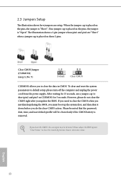
... password, date, time, and user default profile will be detected. English 13 If you update the BIOS. 2.3 Jumpers Setup The illustration shows how jumpers are "Short" when a jumper cap is placed on the pins, the jumper is "Short". Please adjust the BIOS option "Clear Status" to default setup, please turn off the computer and unplug the power cord from the power supply. To clear and reset the system parameters to clear the record of previous chassis...
... password, date, time, and user default profile will be detected. English 13 If you update the BIOS. 2.3 Jumpers Setup The illustration shows how jumpers are "Short" when a jumper cap is placed on the pins, the jumper is "Short". Please adjust the BIOS option "Clear Status" to default setup, please turn off the computer and unplug the power cord from the power supply. To clear and reset the system parameters to clear the record of previous chassis...
User Manual
Page 19
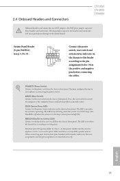
2.4 Onboard Headers and Connectors J3710M J3160M J3060M Onboard headers and connectors are matched correctly. System Panel Header (9-pin PANEL1) (see p.5, No. 9) PLED+ PLEDPWRBTN# GND 1 GND RESET# GND HDLEDHDLED+ Connect the power switch, reset switch and system status indicator on the chassis to this header, make sure the wire assignments and the pin assignments are NOT jumpers. The LED keeps blinking when the system is operating. A front panel module mainly consists of power switch, reset switch, power LED, hard drive activity LED, speaker and etc. RESET (Reset Switch): Connect...
2.4 Onboard Headers and Connectors J3710M J3160M J3060M Onboard headers and connectors are matched correctly. System Panel Header (9-pin PANEL1) (see p.5, No. 9) PLED+ PLEDPWRBTN# GND 1 GND RESET# GND HDLEDHDLED+ Connect the power switch, reset switch and system status indicator on the chassis to this header, make sure the wire assignments and the pin assignments are NOT jumpers. The LED keeps blinking when the system is operating. A front panel module mainly consists of power switch, reset switch, power LED, hard drive activity LED, speaker and etc. RESET (Reset Switch): Connect...

User Manual
Page 21
... Control panel and adjust "Recording Volume". D. To activate the front mic, go to install your system. 2. To use an AC'97 audio panel, please install it along Pin 1 and Pin 13. C. High Definition Audio supports Jack Sensing, but the panel wire on the chassis must support HDA to this header. B. Chassis Speaker Header (4-pin SPEAKER1) (see p.5, No. 8) Chassis Fan Connector (3-pin CHA_FAN1) (see p.5, No. 6) CPU Fan Connector (3-pin CPU_FAN1) (see p.5, No. 3) ATX Power Connector (24-pin ATXPWR1) (see p.5, No. 5) DUMMY SPEAKER 1 +5V DUMMY Please connect...
... Control panel and adjust "Recording Volume". D. To activate the front mic, go to install your system. 2. To use an AC'97 audio panel, please install it along Pin 1 and Pin 13. C. High Definition Audio supports Jack Sensing, but the panel wire on the chassis must support HDA to this header. B. Chassis Speaker Header (4-pin SPEAKER1) (see p.5, No. 8) Chassis Fan Connector (3-pin CHA_FAN1) (see p.5, No. 6) CPU Fan Connector (3-pin CPU_FAN1) (see p.5, No. 3) ATX Power Connector (24-pin ATXPWR1) (see p.5, No. 5) DUMMY SPEAKER 1 +5V DUMMY Please connect...

User Manual
Page 23
... system will be auto-detected and listed on the support CD driver page. Click on the file "ASRSETUP.EXE" in your computer. Utilities Menu The Utilities Menu shows the application software that enhance the motherboard's features. Chapter 3 Software and Utilities Operation 3.1 Installing Drivers The Support CD that comes with the motherboard contains necessary drivers and useful utilities that the motherboard supports. Drivers Menu The drivers compatible to install those required drivers. Therefore, the drivers you install can work properly. Please click...
... system will be auto-detected and listed on the support CD driver page. Click on the file "ASRSETUP.EXE" in your computer. Utilities Menu The Utilities Menu shows the application software that enhance the motherboard's features. Chapter 3 Software and Utilities Operation 3.1 Installing Drivers The Support CD that comes with the motherboard contains necessary drivers and useful utilities that the motherboard supports. Drivers Menu The drivers compatible to install those required drivers. Therefore, the drivers you install can work properly. Please click...

User Manual
Page 24
... tabs or buttons that when selected the information panel below displays the relative information. Double-click utility. Click on your desktop to access ASRock Live Update & APP Shop *You need to be connected to the Internet to perform job-related tasks. With ASRock Live Update & APP Shop, you can quickly and easily install various apps and support utilities, such as USB Key, XFast LAN, XFast RAM and more...
... tabs or buttons that when selected the information panel below displays the relative information. Double-click utility. Click on your desktop to access ASRock Live Update & APP Shop *You need to be connected to the Internet to perform job-related tasks. With ASRock Live Update & APP Shop, you can quickly and easily install various apps and support utilities, such as USB Key, XFast LAN, XFast RAM and more...

User Manual
Page 30
... the Windows 7 inbox drivers, users may find another computer and follow the instructions below and go ahead to install Windows® 7 OS. Then use the new patched Windows® 7 installation USB drive to disabled after the installation. Due to that fact that XHCI is an optical disc drive but no PS/2 ports on your computer, please enable the "PS/2 Simulator" option in UEFI SETUP UTILITY > Advanced > USB Configuration, which allows the USB port to...
... the Windows 7 inbox drivers, users may find another computer and follow the instructions below and go ahead to install Windows® 7 OS. Then use the new patched Windows® 7 installation USB drive to disabled after the installation. Due to that fact that XHCI is an optical disc drive but no PS/2 ports on your computer, please enable the "PS/2 Simulator" option in UEFI SETUP UTILITY > Advanced > USB Configuration, which allows the USB port to...

User Manual
Page 31
Step 4 Select the "USB Driver Folder" by clicking the red circle as shown as the picture below . If you are using ASRock's Support CD for the USB 3.0 driver, please select your system. Step 2 Extract the tool (Win7 USB Patcher) and launch it. Step 3 Select the "Win7 Folder" from Step1 by clicking the red circle as shown as the picture below . Instructions Step 1 Insert the Windows® 7 installation disk or USB drive to your CD-ROM. 26 English
Step 4 Select the "USB Driver Folder" by clicking the red circle as shown as the picture below . If you are using ASRock's Support CD for the USB 3.0 driver, please select your system. Step 2 Extract the tool (Win7 USB Patcher) and launch it. Step 3 Select the "Win7 Folder" from Step1 by clicking the red circle as shown as the picture below . Instructions Step 1 Insert the Windows® 7 installation disk or USB drive to your CD-ROM. 26 English
User Manual
Page 33
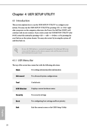
... selections: Main For setting system time/date information Advanced For advanced system configurations Tool Useful tools H/W Monitor Displays current hardware status Security For security settings Boot For configuring boot settings and boot priority Exit Exit the current screen or the UEFI Setup Utility English 28 You may also restart by pressing or right after POST, restart the system by pressing + + , or by pressing the reset button on the system chassis.
... selections: Main For setting system time/date information Advanced For advanced system configurations Tool Useful tools H/W Monitor Displays current hardware status Security For security settings Boot For configuring boot settings and boot priority Exit Exit the current screen or the UEFI Setup Utility English 28 You may also restart by pressing or right after POST, restart the system by pressing + + , or by pressing the reset button on the system chassis.
User Manual
Page 39
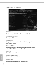
... VGA. Onboard HD Audio Enable/disable onboard HD audio. Front Panel Enable/disable front panel HD audio. Onboard HDMI HD Audio Enable audio for the onboard digital outputs. Share Memory Configure the size of memory that is allocated to enable onboard HD audio and automatically disable it when a sound card is [Auto]. Set to Auto to the integrated graphics processor when the system boots up. The default value is installed. Onboard LAN Enable or disable the onboard network interface controller. 34 English 4.3.2 Chipset Configuration DRAM Voltage Use this to configure DRAM...
... VGA. Onboard HD Audio Enable/disable onboard HD audio. Front Panel Enable/disable front panel HD audio. Onboard HDMI HD Audio Enable audio for the onboard digital outputs. Share Memory Configure the size of memory that is allocated to enable onboard HD audio and automatically disable it when a sound card is [Auto]. Set to Auto to the integrated graphics processor when the system boots up. The default value is installed. Onboard LAN Enable or disable the onboard network interface controller. 34 English 4.3.2 Chipset Configuration DRAM Voltage Use this to configure DRAM...
User Manual
Page 43
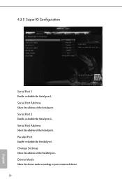
Serial Port Address Select the address of the Serial port. Device Mode Select the device mode according to your connected device. 38 English Serial Port 2 Enable or disable the Serial port 2. Parallel Port Enable or disable the Parallel port. Serial Port Address Select the address of the Serial port. 4.3.5 Super IO Configuration Serial Port 1 Enable or disable the Serial port 1. Change Settings Select the address of the Parallel port.
Serial Port Address Select the address of the Serial port. Device Mode Select the device mode according to your connected device. 38 English Serial Port 2 Enable or disable the Serial port 2. Parallel Port Enable or disable the Parallel port. Serial Port Address Select the address of the Serial port. 4.3.5 Super IO Configuration Serial Port 1 Enable or disable the Serial port 1. Change Settings Select the address of the Parallel port.

User Manual
Page 48
Internet Flash ASRock Internet Flash downloads and updates the latest UEFI firmware version from our servers for you. 4.4 Tools J3710M J3160M J3060M Instant Flash Save UEFI files in your UEFI. Please setup network configuration before using Internet Flash. *For BIOS backup and recovery purpose, it is recommended to plug in your USB storage device and run Instant Flash to update your USB pen drive before using this function. 43 English
Internet Flash ASRock Internet Flash downloads and updates the latest UEFI firmware version from our servers for you. 4.4 Tools J3710M J3160M J3060M Instant Flash Save UEFI files in your UEFI. Please setup network configuration before using Internet Flash. *For BIOS backup and recovery purpose, it is recommended to plug in your USB storage device and run Instant Flash to update your USB pen drive before using this function. 43 English
User Manual
Page 49
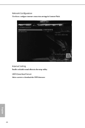
Internet Setting Enable or disable sound effects in the setup utility. UEFI Download Server Select a server to configure internet connection settings for Internet Flash. Network Configuration Use this to download the UEFI firmware. 44 English
Internet Setting Enable or disable sound effects in the setup utility. UEFI Download Server Select a server to configure internet connection settings for Internet Flash. Network Configuration Use this to download the UEFI firmware. 44 English
User Manual
Page 50
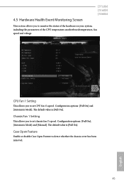
... default value is [Full On]. Chassis Fan 1 Setting This allows you to set chassis fan 1's speed. Configuration options: [Full On], [Automatic Mode] and [Manual]. The default value is [Full On]. Configuration options: [Full On] and [Automatic Mode]. Case Open Feature Enable or disable Case Open Feature to monitor the status of the hardware on your system, including the parameters of the CPU temperature, motherboard temperature, fan speed and voltage. CPU Fan 1 Setting This allows you to set CPU fan 1's speed. 4.5 Hardware Health Event Monitoring Screen J3710M J3160M J3060M...
... default value is [Full On]. Chassis Fan 1 Setting This allows you to set chassis fan 1's speed. Configuration options: [Full On], [Automatic Mode] and [Manual]. The default value is [Full On]. Configuration options: [Full On] and [Automatic Mode]. Case Open Feature Enable or disable Case Open Feature to monitor the status of the hardware on your system, including the parameters of the CPU temperature, motherboard temperature, fan speed and voltage. CPU Fan 1 Setting This allows you to set CPU fan 1's speed. 4.5 Hardware Health Event Monitoring Screen J3710M J3160M J3060M...


