
User Manual
Page 3
... apply to products (including HDD, ODD, memory and warranty seal) that the total ampere rating of the devices plugged into the system. • The system does not function properly even if you follow all power, modem, and network cables from the power outlets before you encounter the following safety instructions. If you read the following technical problems with ambient temperatures between...
... apply to products (including HDD, ODD, memory and warranty seal) that the total ampere rating of the devices plugged into the system. • The system does not function properly even if you follow all power, modem, and network cables from the power outlets before you encounter the following safety instructions. If you read the following technical problems with ambient temperatures between...
User Manual
Page 5
...System Components Reinstallation ...Driver Installation ...UTILITY MEMU ...5.1 Instant Boot ...5.1.1 Introduction ...5.1.2 Installation ...5.2 ASRock OC Tuner ...5.2.1 Introduction ...5.2.2 Installation ...6.1 Introduction ...6.1.1 BIOS Menu Bar ...6.1.2 Navigation Keys ...6.2 Main Screen ...6.3 Smart Screen ...6.4 Advanced Screen ...6.4.1 CPU Configuration ...6.4.2 Chipset Configuration ...6.4.3 ACPI Configuration ...6.4.4 SATA Configuration ...6.4.5 USB Configuration ...6.5 Fan Control ...6.6 Boot Screen ...6.6.1 Boot Settings Configuration ...6.7 Security Screen ...6.8 Exit Screen ... 14 17...
...System Components Reinstallation ...Driver Installation ...UTILITY MEMU ...5.1 Instant Boot ...5.1.1 Introduction ...5.1.2 Installation ...5.2 ASRock OC Tuner ...5.2.1 Introduction ...5.2.2 Installation ...6.1 Introduction ...6.1.1 BIOS Menu Bar ...6.1.2 Navigation Keys ...6.2 Main Screen ...6.3 Smart Screen ...6.4 Advanced Screen ...6.4.1 CPU Configuration ...6.4.2 Chipset Configuration ...6.4.3 ACPI Configuration ...6.4.4 SATA Configuration ...6.4.5 USB Configuration ...6.5 Fan Control ...6.6 Boot Screen ...6.6.1 Boot Settings Configuration ...6.7 Security Screen ...6.8 Exit Screen ... 14 17...
User Manual
Page 7
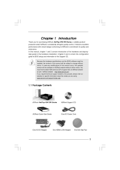
... guide to the hardware installation. In case any modifications of this product, please visit our website for purchasing ASRock NetTop ION 330 Series, a reliable product produced under ASRock's consistently stringent quality control. ASRock website http://www.asrock.com If you for specific information about the model you are using. www.asrock.com/support/index.asp 1.1 Package Contents ASRock NetTop ION 330 Series ASRock Support CD ASRock Quick Start Guide One AC Power Cord One AC/DC Adapter One HDMI...
... guide to the hardware installation. In case any modifications of this product, please visit our website for purchasing ASRock NetTop ION 330 Series, a reliable product produced under ASRock's consistently stringent quality control. ASRock website http://www.asrock.com If you for specific information about the model you are using. www.asrock.com/support/index.asp 1.1 Package Contents ASRock NetTop ION 330 Series ASRock Support CD ASRock Quick Start Guide One AC Power Cord One AC/DC Adapter One HDMI...
User Manual
Page 8
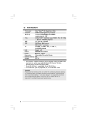
... there is supported by overclocking. 8 1.2 Specifications Intel® AtomTM 330 (Dual-Core CPU) NVIDIA® IONTM graphics processor Support DDR2 800MHz, 2 x DIMMs, maximun up to 4GB * NVIDIA® IONTM Graphics, support DX10 / Full HD 1080p ** (Blu-ray / HD-DVD) playback 2.5" HDD up to 500GB DVD Super Multi (ION 330) BD Combo*** (ION 330-BD) 1 x HDMI, 1 x D-Sub VGA, 6 x USB 2.0, 1 x S/PDIF (Optical) Gigabit LAN HD Audio 5.1 channel 65W/19V Adapter 195mm(W)x70mm(H)x186m(L) 2.5L 1.75 Kg Processor Chipset Memory VGA HDD DVD I/O LAN Sound Power Dimension...
... there is supported by overclocking. 8 1.2 Specifications Intel® AtomTM 330 (Dual-Core CPU) NVIDIA® IONTM graphics processor Support DDR2 800MHz, 2 x DIMMs, maximun up to 4GB * NVIDIA® IONTM Graphics, support DX10 / Full HD 1080p ** (Blu-ray / HD-DVD) playback 2.5" HDD up to 500GB DVD Super Multi (ION 330) BD Combo*** (ION 330-BD) 1 x HDMI, 1 x D-Sub VGA, 6 x USB 2.0, 1 x S/PDIF (Optical) Gigabit LAN HD Audio 5.1 channel 65W/19V Adapter 195mm(W)x70mm(H)x186m(L) 2.5L 1.75 Kg Processor Chipset Memory VGA HDD DVD I/O LAN Sound Power Dimension...

User Manual
Page 10
SATA and Power Connections SATA & Power Connections HDD ODD Connect to ODD Connect to HDD Connect to SATA Connector (14) Connect to ATX5V Power Connector (15) Connect to SATA Connector (16) 2. System Memory Socket Connection 2 2 1 1 1 1 Installing a memory module Removing a memory module 3. CPU Fan Connection CPU fan connector SYS_FAN_TACH +12V Ground 10 System Fan Connection System fan connector Ground +12V Rotation 4. NOTE. 1.
SATA and Power Connections SATA & Power Connections HDD ODD Connect to ODD Connect to HDD Connect to SATA Connector (14) Connect to ATX5V Power Connector (15) Connect to SATA Connector (16) 2. System Memory Socket Connection 2 2 1 1 1 1 Installing a memory module Removing a memory module 3. CPU Fan Connection CPU fan connector SYS_FAN_TACH +12V Ground 10 System Fan Connection System fan connector Ground +12V Rotation 4. NOTE. 1.

User Manual
Page 12
1.5 System Chassis Opening the system chassis 1. HDMI 26 28 27 26. Drive activity indicator 28. Slide the top panel backwards. Power ON/OFF button with status indicator 12 Optical Disc Drive 27. Remove the screws on the backside. 2.
1.5 System Chassis Opening the system chassis 1. HDMI 26 28 27 26. Drive activity indicator 28. Slide the top panel backwards. Power ON/OFF button with status indicator 12 Optical Disc Drive 27. Remove the screws on the backside. 2.

User Manual
Page 13
Optical Disc Drive 31. 1.6 Internal System Components Optical disc & Hard disk drives The optical disc and hard disc drives are mounted in a drive cage. The cage can be removed by removing the top screws. 31 29 30 29. System Cooling Fan 30. Hard Disc Drive 13
Optical Disc Drive 31. 1.6 Internal System Components Optical disc & Hard disk drives The optical disc and hard disc drives are mounted in a drive cage. The cage can be removed by removing the top screws. 31 29 30 29. System Cooling Fan 30. Hard Disc Drive 13

User Manual
Page 15
5. Connecting Power (DC-In Jack Port) 8. Connecting HDMI Device (HDMI Port) 15 Connecting Stereo Speakers or Headphones (Front L/R Out Port) 6. Connecting External Audio Device (Line In Port) 7.
5. Connecting Power (DC-In Jack Port) 8. Connecting HDMI Device (HDMI Port) 15 Connecting Stereo Speakers or Headphones (Front L/R Out Port) 6. Connecting External Audio Device (Line In Port) 7.

User Manual
Page 19
Chapter 4 Driver Installation To install the drivers to your system, please insert the support CD to install those required drivers. Then, the drivers compatible to your optical drive first. Therefore, the drivers you install can be auto-detected and listed on the support CD driver page. Please follow the order from up to bottom side to your system can work properly. 19
Chapter 4 Driver Installation To install the drivers to your system, please insert the support CD to install those required drivers. Then, the drivers compatible to your optical drive first. Therefore, the drivers you install can be auto-detected and listed on the support CD driver page. Please follow the order from up to bottom side to your system can work properly. 19

User Manual
Page 21
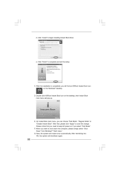
... you need , and click "Next". 21 b. Install Instant Boot driver from ASRock support CD, or you need , and click "Next". a. Select destination location. Select the start menu folder. You may choose a different folder if you may choose a different folder if you install Instant Boot. Please follow the instructions on Instant Boot setup page. Click "Next" to get the latest utility and BIOS: http://www.asrock.com/feature/InstantBoot/download...
... you need , and click "Next". 21 b. Install Instant Boot driver from ASRock support CD, or you need , and click "Next". a. Select destination location. Select the start menu folder. You may choose a different folder if you may choose a different folder if you install Instant Boot. Please follow the instructions on Instant Boot setup page. Click "Next" to get the latest utility and BIOS: http://www.asrock.com/feature/InstantBoot/download...
User Manual
Page 22
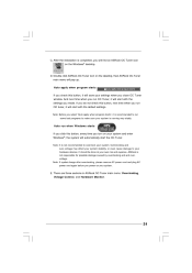
... "Fast Mode", "Regular Mode" or "Disable Instant Boot". G. After reentering into OS, the system will find an ASRock Instant Boot icon on the desktop, then Instant Boot main menu will restart once automatically. Click "Finish" to shut down the computer, please simply select "Shut Down" from Windows® "Start menu". Please notice that , please click "Apply" to begin installing Instant Boot driver. C. On Instant Boot main menu...
... "Fast Mode", "Regular Mode" or "Disable Instant Boot". G. After reentering into OS, the system will find an ASRock Instant Boot icon on the desktop, then Instant Boot main menu will restart once automatically. Click "Finish" to shut down the computer, please simply select "Shut Down" from Windows® "Start menu". Please notice that , please click "Apply" to begin installing Instant Boot driver. C. On Instant Boot main menu...
User Manual
Page 25
... your own risk and expense. Note: Before you turn on the desktop, then ASRock OC Tuner main menu will save your system is not responsible for possible damage caused by overclocking and and overvoltage. There are three sections in ASRock OC Tuner main menu: Overclocking, Voltage Control, and Hardware Monitor . 25 C. Auto run OC Tuner, it will automatically start with the default settings.
... your own risk and expense. Note: Before you turn on the desktop, then ASRock OC Tuner main menu will save your system is not responsible for possible damage caused by overclocking and and overvoltage. There are three sections in ASRock OC Tuner main menu: Overclocking, Voltage Control, and Hardware Monitor . 25 C. Auto run OC Tuner, it will automatically start with the default settings.
User Manual
Page 27
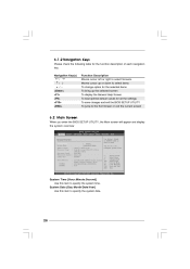
... the advanced BIOS features To display current fan speed status To set up the default system device to choose among the selections on . You may not exactly match what you start up the security features Exit To exit the current screen or the BIOS SETUP UTILITY Use < > key or < > key to locate and load the Operating System Security To set up the computer. You may run the BIOS SETUP UTILITY when you...
... the advanced BIOS features To display current fan speed status To set up the default system device to choose among the selections on . You may not exactly match what you start up the security features Exit To exit the current screen or the BIOS SETUP UTILITY Use < > key or < > key to locate and load the Operating System Security To set up the computer. You may run the BIOS SETUP UTILITY when you...
User Manual
Page 28
... display the system overview BIOS SETUP UTILITY Advanced Fan Control Boot Main Smart Security Exit System Overview System Time System Date [14:00:09] [Thu 04/23/2009] : AMCP7A-ION P1.00 : Intel (R) Atom (TM) CPU 330 @ 1.60GHz (64bit) Processor Speed : 1600MHz Microcode Update : 106C2/213 Cache Size : 1024KB BIOS Version Processor Type Total Memory DDRII1 DDRII2 : 1024MB with 128MB shared memory Single-Channel Memory Mode : 1024MB/400MHz (DDRII800) : None Use [Enter...
... display the system overview BIOS SETUP UTILITY Advanced Fan Control Boot Main Smart Security Exit System Overview System Time System Date [14:00:09] [Thu 04/23/2009] : AMCP7A-ION P1.00 : Intel (R) Atom (TM) CPU 330 @ 1.60GHz (64bit) Processor Speed : 1600MHz Microcode Update : 106C2/213 Cache Size : 1024KB BIOS Version Processor Type Total Memory DDRII1 DDRII2 : 1024MB with 128MB shared memory Single-Channel Memory Mode : 1024MB/400MHz (DDRII800) : None Use [Enter...
User Manual
Page 31
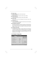
... select [Enabled] to enable CPU internal thermal control mechanism to keep the CPU from being used by malicious software to [Enabled] if using Microsoft® Windows® XP, or Linux kernel version 2.4.18 or higher. 6.4.2 Chipset Configuration BIOS SETUP UTILITY Advanced Chipset Settings DRAM Frequency Memory Timings Onboard LAN Onboard HDMI HD Audio Onboard HD Audio Share Memory Onboard GPU Clock VCORE Voltage (VCCM) DRAM Voltage Chipset Core Voltage [Auto] [Auto] [Enabled] [Disabled] [Enabled] [Auto...
... select [Enabled] to enable CPU internal thermal control mechanism to keep the CPU from being used by malicious software to [Enabled] if using Microsoft® Windows® XP, or Linux kernel version 2.4.18 or higher. 6.4.2 Chipset Configuration BIOS SETUP UTILITY Advanced Chipset Settings DRAM Frequency Memory Timings Onboard LAN Onboard HDMI HD Audio Onboard HD Audio Share Memory Onboard GPU Clock VCORE Voltage (VCCM) DRAM Voltage Chipset Core Voltage [Auto] [Auto] [Enabled] [Disabled] [Enabled] [Auto...
User Manual
Page 32
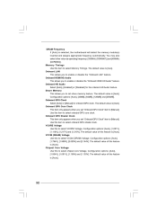
... Voltage Use this to enable or disable the "Onboard HDMI HD Audio" feature. VCCM (DRAM) Voltage Use this to select Memory Timings. Chipset Core Voltage Use this item to select VCORE Voltage. The default value is selected, the motherboard will detect the memory module(s) inserted and assigns appropriate frequency automatically. Onboard GPU Clock Select [Auto] or [Manual] for the onboard HD Audio feature. Configuration options...
... Voltage Use this to enable or disable the "Onboard HDMI HD Audio" feature. VCCM (DRAM) Voltage Use this to select Memory Timings. Chipset Core Voltage Use this item to select VCORE Voltage. The default value is selected, the motherboard will detect the memory module(s) inserted and assigns appropriate frequency automatically. Onboard GPU Clock Select [Auto] or [Manual] for the onboard HD Audio feature. Configuration options...

User Manual
Page 33
... or disable the Suspend-to boot up when the power recovers. 6.4.3 ACPI Configuration BIOS SETUP UTILITY Advanced ACPI Settings Suspend To RAM Check Ready Bit Restore on AC/Power Loss This allows you to set the power state after an unexpected AC/Power loss. Restore on AC / Power Loss Onboard LAN Power On RTC Alarm Power On ACPI HPET Table [Auto] [Enabled] [Power Off] [Disabled] [Disabled] [Disabled] Select Screen Select Item Change Option General Help Load Defaults Save...
... or disable the Suspend-to boot up when the power recovers. 6.4.3 ACPI Configuration BIOS SETUP UTILITY Advanced ACPI Settings Suspend To RAM Check Ready Bit Restore on AC/Power Loss This allows you to set the power state after an unexpected AC/Power loss. Restore on AC / Power Loss Onboard LAN Power On RTC Alarm Power On ACPI HPET Table [Auto] [Enabled] [Power Off] [Disabled] [Disabled] [Disabled] Select Screen Select Item Change Option General Help Load Defaults Save...

User Manual
Page 35
... Options Fan Control F1 F9 F10 ESC Select Screen Select Item General Help Load Defaults Save and Exit Exit v02.54 (C) Copyright 1985-2003, American Megatrends, Inc. 6.6 Boot Screen In this section, it will display the available devices on your system for you to monitor the status of the fan speed. BIOS SETUP UTILITY Advanced Fan Control Boot Security Main Smart Exit Boot Settings Boot Settings Configuration 1st Boot Device 2nd Boot Device Hard Disk Drives CD/DVD Drives [HDD: PM - ROM C] Configure Settings during System Boot...
... Options Fan Control F1 F9 F10 ESC Select Screen Select Item General Help Load Defaults Save and Exit Exit v02.54 (C) Copyright 1985-2003, American Megatrends, Inc. 6.6 Boot Screen In this section, it will display the available devices on your system for you to monitor the status of the fan speed. BIOS SETUP UTILITY Advanced Fan Control Boot Security Main Smart Exit Boot Settings Boot Settings Configuration 1st Boot Device 2nd Boot Device Hard Disk Drives CD/DVD Drives [HDD: PM - ROM C] Configure Settings during System Boot...

User Manual
Page 37
For the user password, you may also clear it. Enter F1 F9 F10 ESC Select Screen Select Item Change General Help Load Defaults Save and Exit Exit v02.54 (C) Copyright 1985-2005, American Megatrends, Inc. 37 BIOS SETUP UTILITY Advanced Fan Control Boot Main Smart Security Exit Security Settings Supervisor Password : Not Installed User Password : Not Installed Change Supervisor Password Change User Password Install or Change the password. 6.7 Security Screen In this section, you may set or change the supervisor/user password for the system.
For the user password, you may also clear it. Enter F1 F9 F10 ESC Select Screen Select Item Change General Help Load Defaults Save and Exit Exit v02.54 (C) Copyright 1985-2005, American Megatrends, Inc. 37 BIOS SETUP UTILITY Advanced Fan Control Boot Main Smart Security Exit Security Settings Supervisor Password : Not Installed User Password : Not Installed Change Supervisor Password Change User Password Install or Change the password. 6.7 Security Screen In this section, you may set or change the supervisor/user password for the system.

User Manual
Page 39
... detects installed devices. Please install the necessary drivers to know more information. 7 . 2 Support CD Information The Support CD contains necessary drivers and useful utilities that the system supports. or you need to contact ASRock or want to activate the devices. 7 . 2 . 3 Utilities Menu The Utilities Menu shows the applications software that enhance the system features. 7 . 2 . 1 Running The Support CD To begin using the support CD, insert the CD into your CD-ROM drive. Chapter 7 Software Support 7 . 1 Install Operating System...
... detects installed devices. Please install the necessary drivers to know more information. 7 . 2 Support CD Information The Support CD contains necessary drivers and useful utilities that the system supports. or you need to contact ASRock or want to activate the devices. 7 . 2 . 3 Utilities Menu The Utilities Menu shows the applications software that enhance the system features. 7 . 2 . 1 Running The Support CD To begin using the support CD, insert the CD into your CD-ROM drive. Chapter 7 Software Support 7 . 1 Install Operating System...


