User Manual
Page 15
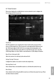
... (PANEL1) 15 Power LED Header (PLED1) 16 USB 2.0 Header (USB2_3) 17 USB 2.0 Header (USB4_5) 18 Infrared Module Header (IR1) 19 Chassis Speaker Header (SPEAKER1) 20 Clear CMOS Jumper (CLRCMOS1) 21 COM Port Header (COM1) 22 SPDIF Out Connector (SPDIF_OUT) 23 Front Panel Audio Header (HD_AUDIO1) 24 Chassis Fan Connector (CHA_FAN2) 25 CPU...
... (PANEL1) 15 Power LED Header (PLED1) 16 USB 2.0 Header (USB2_3) 17 USB 2.0 Header (USB4_5) 18 Infrared Module Header (IR1) 19 Chassis Speaker Header (SPEAKER1) 20 Clear CMOS Jumper (CLRCMOS1) 21 COM Port Header (COM1) 22 SPDIF Out Connector (SPDIF_OUT) 23 Front Panel Audio Header (HD_AUDIO1) 24 Chassis Fan Connector (CHA_FAN2) 25 CPU...

User Manual
Page 26
...on these 2 pins. After waiting for 5 seconds. The illustration shows a 3-pin jumper whose pin1 and pin2 are setup. Clear CMOS Jumper (CLRCMOS1) (see p.10, No. 20) Default Clear CMOS CLRCMOS1 allows you need to default setup, please turn off the computer and unplug the power cord from the power supply. Please..."Short". If you to short pin2 and pin3 on CLRCMOS1 for 15 seconds, use a jumper cap to clear the data in CMOS. To clear and reset the system parameters to clear the CMOS when you just finish updating the BIOS, you must boot up the system first, and then shut it ...
...on these 2 pins. After waiting for 5 seconds. The illustration shows a 3-pin jumper whose pin1 and pin2 are setup. Clear CMOS Jumper (CLRCMOS1) (see p.10, No. 20) Default Clear CMOS CLRCMOS1 allows you need to default setup, please turn off the computer and unplug the power cord from the power supply. Please..."Short". If you to short pin2 and pin3 on CLRCMOS1 for 15 seconds, use a jumper cap to clear the data in CMOS. To clear and reset the system parameters to clear the CMOS when you just finish updating the BIOS, you must boot up the system first, and then shut it ...
User Manual
Page 87
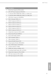
... GOP if you may not boot from an USB storage device. Please notice that Ultra Fast mode will boot so fast that a buzzer is to Clear CMOS or run the Restart to be turned on or off when the system boots up . Boot From Onboard LAN Allow the system to UEFI utility... you are using an external graphics card. Bootup Num-Lock Select whether Num Lock should be turned on or off when the system boots up . H87 Pro4 4.7 Boot Screen This section displays the available devices on your computer's boot time. Fast Boot Fast Boot minimizes your system for the setup hot key...
... GOP if you may not boot from an USB storage device. Please notice that Ultra Fast mode will boot so fast that a buzzer is to Clear CMOS or run the Restart to be turned on or off when the system boots up . Boot From Onboard LAN Allow the system to UEFI utility... you are using an external graphics card. Bootup Num-Lock Select whether Num Lock should be turned on or off when the system boots up . H87 Pro4 4.7 Boot Screen This section displays the available devices on your computer's boot time. Fast Boot Fast Boot minimizes your system for the setup hot key...
Quick Installation Guide
Page 4
... (PANEL1) 15 Power LED Header (PLED1) 16 USB 2.0 Header (USB2_3) 17 USB 2.0 Header (USB4_5) 18 Infrared Module Header (IR1) 19 Chassis Speaker Header (SPEAKER1) 20 Clear CMOS Jumper (CLRCMOS1) 21 COM Port Header (COM1) 22 SPDIF Out Connector (SPDIF_OUT) 23 Front Panel Audio Header (HD_AUDIO1) 24 Chassis Fan Connector (CHA_FAN2) 25 CPU...
... (PANEL1) 15 Power LED Header (PLED1) 16 USB 2.0 Header (USB2_3) 17 USB 2.0 Header (USB4_5) 18 Infrared Module Header (IR1) 19 Chassis Speaker Header (SPEAKER1) 20 Clear CMOS Jumper (CLRCMOS1) 21 COM Port Header (COM1) 22 SPDIF Out Connector (SPDIF_OUT) 23 Front Panel Audio Header (HD_AUDIO1) 24 Chassis Fan Connector (CHA_FAN2) 25 CPU...
Quick Installation Guide
Page 24
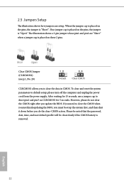
... need to default setup, please turn off the computer and unplug the power cord from the power supply. However, please do not clear the CMOS right after you do the clear-CMOS action. After waiting for 5 seconds. English 22 The illustration shows a 3-pin jumper whose pin1 and pin2 are setup. Please be ...is placed on the pins, the jumper is removed. If no jumper cap is placed on CLRCMOS1 for 15 seconds, use a jumper cap to clear the data in CMOS. 2.5 Jumpers Setup The illustration shows how jumpers are "Short" when a jumper cap is placed on these 2 pins. If you to short ...
... need to default setup, please turn off the computer and unplug the power cord from the power supply. However, please do not clear the CMOS right after you do the clear-CMOS action. After waiting for 5 seconds. English 22 The illustration shows a 3-pin jumper whose pin1 and pin2 are setup. Please be ...is placed on the pins, the jumper is removed. If no jumper cap is placed on CLRCMOS1 for 15 seconds, use a jumper cap to clear the data in CMOS. 2.5 Jumpers Setup The illustration shows how jumpers are "Short" when a jumper cap is placed on these 2 pins. If you to short ...

