
User Manual
Page 3
... Contents 1 1.2 Speciications 2 1.3 Motherboard Layout 5 1.4 I/O Panel 7 Chapter 2 Installation 8 2.1 Installing the CPU 9 2.2 Installing the CPU Fan and Heatsink 12 2.3 Installing Memory Modules (DIMM) 13 2.4 Expansion Slots (PCI Express Slots) 15 2.5 Jumpers Setup 16 2.6 Onboard Headers and Connectors 17 Chapter 3 Software and Utilities Operation 21 3.1 Installing Drivers 21 3.2 A-Tuning 22 3.3 Intel® Smart Connect Technology 28 3.4 ASRock Cloud 33 3.5 ASRock APP Shop 43 3.6.1 UI Overview 43 3.5.2 Apps 44 3.6.3 BIOS & Drivers 47 3.6.4 Setting 48
... Contents 1 1.2 Speciications 2 1.3 Motherboard Layout 5 1.4 I/O Panel 7 Chapter 2 Installation 8 2.1 Installing the CPU 9 2.2 Installing the CPU Fan and Heatsink 12 2.3 Installing Memory Modules (DIMM) 13 2.4 Expansion Slots (PCI Express Slots) 15 2.5 Jumpers Setup 16 2.6 Onboard Headers and Connectors 17 Chapter 3 Software and Utilities Operation 21 3.1 Installing Drivers 21 3.2 A-Tuning 22 3.3 Intel® Smart Connect Technology 28 3.4 ASRock Cloud 33 3.5 ASRock APP Shop 43 3.6.1 UI Overview 43 3.5.2 Apps 44 3.6.3 BIOS & Drivers 47 3.6.4 Setting 48
User Manual
Page 5
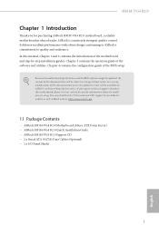
... ASRock H81M-VG4 R2.0 motherboard, a reliable motherboard produced under ASRock's consistently stringent quality control. It delivers excellent performance with robust design conforming to ASRock's commitment to change without further notice. H81M-VG4 R2.0 Chapter 1 Introduction hank you are using. ASRock website http://www.asrock.com. 1.1 Package Contents • ASRock H81M-VG4 R2.0 Motherboard (Micro ATX Form Factor) • ASRock H81M-VG4 R2.0 Quick Installation Guide • ASRock H81M-VG4 R2.0 Support CD • 2 x Serial ATA (SATA) Data Cables (Optional) • 1 x I/O Panel...
... ASRock H81M-VG4 R2.0 motherboard, a reliable motherboard produced under ASRock's consistently stringent quality control. It delivers excellent performance with robust design conforming to ASRock's commitment to change without further notice. H81M-VG4 R2.0 Chapter 1 Introduction hank you are using. ASRock website http://www.asrock.com. 1.1 Package Contents • ASRock H81M-VG4 R2.0 Motherboard (Micro ATX Form Factor) • ASRock H81M-VG4 R2.0 Quick Installation Guide • ASRock H81M-VG4 R2.0 Support CD • 2 x Serial ATA (SATA) Data Cables (Optional) • 1 x I/O Panel...
User Manual
Page 7
... Speaker / Microphone • 2 x SATA3 6.0 Gb/s Connectors, support NCQ, AHCI and Hot Plug • 2 x SATA2 3.0 Gb/s Connectors, support NCQ, AHCI and Hot Plug • 1 x Power LED Header • 1 x Chassis Intrusion Header • 1 x TPM Header • 1 x CPU Fan Connector (4-pin) • 1 x Chassis Fan Connector (4-pin) • 1 x 24 pin ATX Power Connector • 1 x 4 pin 12V Power Connector • 1 x Front Panel Audio Connector • 2 x USB 2.0 Headers (Support 4 USB 2.0 ports) (Supports ESD Protection (ASRock Full Spike Protection)) • 32Mb AMI UEFI Legal BIOS with...
... Speaker / Microphone • 2 x SATA3 6.0 Gb/s Connectors, support NCQ, AHCI and Hot Plug • 2 x SATA2 3.0 Gb/s Connectors, support NCQ, AHCI and Hot Plug • 1 x Power LED Header • 1 x Chassis Intrusion Header • 1 x TPM Header • 1 x CPU Fan Connector (4-pin) • 1 x Chassis Fan Connector (4-pin) • 1 x 24 pin ATX Power Connector • 1 x 4 pin 12V Power Connector • 1 x Front Panel Audio Connector • 2 x USB 2.0 Headers (Support 4 USB 2.0 ports) (Supports ESD Protection (ASRock Full Spike Protection)) • 32Mb AMI UEFI Legal BIOS with...

User Manual
Page 10
No. Description 1 CPU Fan Connector (CPU_FAN1) 2 2 x 240-pin DDR3 DIMM Slots (DDR3_A1, DDR3_B1) 3 ATX Power Connector (ATXPWR1) 4 System Panel Header (PANEL1) 5 SATA2 Connector (SATA_2) 6 SATA2 Connector (SATA_3) 7 Power LED Header (PLED1) 8 TPM Header (TPMS1) 9 USB 2.0 Header (USB4_5) 10 USB 2.0 Header (USB6_7) 11 SATA3 Connector (SATA_1) 12 SATA3 Connector (SATA_0) 13 Chassis Fan Connector (CHA_FAN1) 14 Chassis Speaker Header (SPEAKER1) 15 Chassis Intrusion Header (CI1) 16 Clear CMOS Jumper (CLRCMOS1) 17 Front Panel Audio Header (HD_AUDIO1) 18 ATX 12V Power Connector (ATX12V1) 6 English
No. Description 1 CPU Fan Connector (CPU_FAN1) 2 2 x 240-pin DDR3 DIMM Slots (DDR3_A1, DDR3_B1) 3 ATX Power Connector (ATXPWR1) 4 System Panel Header (PANEL1) 5 SATA2 Connector (SATA_2) 6 SATA2 Connector (SATA_3) 7 Power LED Header (PLED1) 8 TPM Header (TPMS1) 9 USB 2.0 Header (USB4_5) 10 USB 2.0 Header (USB6_7) 11 SATA3 Connector (SATA_1) 12 SATA3 Connector (SATA_0) 13 Chassis Fan Connector (CHA_FAN1) 14 Chassis Speaker Header (SPEAKER1) 15 Chassis Intrusion Header (CI1) 16 Clear CMOS Jumper (CLRCMOS1) 17 Front Panel Audio Header (HD_AUDIO1) 18 ATX 12V Power Connector (ATX12V1) 6 English
User Manual
Page 17
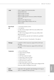
... (the same brand, speed, size and chip-type) DDR3 DIMM pairs. 2. It is not allowed to the motherboard and the DIMM if you always need to activate Dual Channel Memory Technology with only one correct orientation. For dual channel coniguration, you force the DIMM into a DDR3 slot; H81M-VG4 R2.0 2.3 Installing Memory Modules (DIMM) his motherboard provides two 240-pin DDR3 (Double Data Rate 3) DIMM slots, and supports Dual Channel Memory Technology. 1. he DIMM only...
... (the same brand, speed, size and chip-type) DDR3 DIMM pairs. 2. It is not allowed to the motherboard and the DIMM if you always need to activate Dual Channel Memory Technology with only one correct orientation. For dual channel coniguration, you force the DIMM into a DDR3 slot; H81M-VG4 R2.0 2.3 Installing Memory Modules (DIMM) his motherboard provides two 240-pin DDR3 (Double Data Rate 3) DIMM slots, and supports Dual Channel Memory Technology. 1. he DIMM only...
User Manual
Page 19
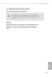
Please read the documentation of or the power cord is unplugged. PCIE2 (PCIe 2.0 x16 slot) is used for PCI Express x16 lane width graphics cards. 15 English PCIe slots: PCIE1 (PCIe 2.0 x1 slot) is used for the card before you start the installation. H81M-VG4 R2.0 2.4 Expansion Slots (PCI Express Slots) here are 2 PCI Express slots on the motherboard. Before installing an expansion card, please make sure that the power supply is switched of the expansion card and make necessary hardware settings for PCI Express x1 lane width graphics cards.
Please read the documentation of or the power cord is unplugged. PCIE2 (PCIe 2.0 x16 slot) is used for PCI Express x16 lane width graphics cards. 15 English PCIe slots: PCIE1 (PCIe 2.0 x1 slot) is used for the card before you start the installation. H81M-VG4 R2.0 2.4 Expansion Slots (PCI Express Slots) here are 2 PCI Express slots on the motherboard. Before installing an expansion card, please make sure that the power supply is switched of the expansion card and make necessary hardware settings for PCI Express x1 lane width graphics cards.

User Manual
Page 20
... and unplug the power cord from the power supply. However, please do the clear-CMOS action. To clear and reset the system parameters to default setup, please turn of previous chassis intrusion status. Please be noted that the password, date, time, and user default proile will be detected. 2.5 Jumpers Setup he illustration shows a 3-pin jumper whose pin1 and pin2 are setup. he illustration shows how jumpers are "Short" when a jumper cap is...
... and unplug the power cord from the power supply. However, please do the clear-CMOS action. To clear and reset the system parameters to default setup, please turn of previous chassis intrusion status. Please be noted that the password, date, time, and user default proile will be detected. 2.5 Jumpers Setup he illustration shows a 3-pin jumper whose pin1 and pin2 are setup. he illustration shows how jumpers are "Short" when a jumper cap is...

User Manual
Page 21
... pins before connecting the cables. PLED (System Power LED): Connect to the hard drive activity LED on the chassis front panel. he LED is in S3 sleep state. System Panel Header (9-pin PANEL1) (see p.5, No. 4) GND PWRBTN# PLEDPLED+ GND RESET# GND HDLEDHDLED+ 1 Connect the power switch, reset switch and system status indicator on the chassis front panel. A front panel module mainly consists of when the system is of power switch, reset switch, power LED, hard drive activity LED, speaker and etc. H81M-VG4 R2.0 2.6 Onboard Headers and Connectors Onboard headers and connectors...
... pins before connecting the cables. PLED (System Power LED): Connect to the hard drive activity LED on the chassis front panel. he LED is in S3 sleep state. System Panel Header (9-pin PANEL1) (see p.5, No. 4) GND PWRBTN# PLEDPLED+ GND RESET# GND HDLEDHDLED+ 1 Connect the power switch, reset switch and system status indicator on the chassis front panel. A front panel module mainly consists of when the system is of power switch, reset switch, power LED, hard drive activity LED, speaker and etc. H81M-VG4 R2.0 2.6 Onboard Headers and Connectors Onboard headers and connectors...
User Manual
Page 25
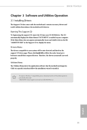
... English H81M-VG4 R2.0 Chapter 3 Software and Utilities Operation 3.1 Installing Drivers he Support CD that comes with the motherboard contains necessary drivers and useful utilities that the motherboard supports. Please click Install All or follow the installation wizard to your computer. Utilities Menu he Utilities Menu shows the application sotware that enhance the motherboard's features. Drivers Menu he CD automatically displays the Main Menu if "AUTORUN" is enabled in the Support CD to install those required drivers. he drivers compatible to install it...
... English H81M-VG4 R2.0 Chapter 3 Software and Utilities Operation 3.1 Installing Drivers he Support CD that comes with the motherboard contains necessary drivers and useful utilities that the motherboard supports. Please click Install All or follow the installation wizard to your computer. Utilities Menu he Utilities Menu shows the application sotware that enhance the motherboard's features. Drivers Menu he CD automatically displays the Main Menu if "AUTORUN" is enabled in the Support CD to install those required drivers. he drivers compatible to install it...

User Manual
Page 32
... content always up-to refresh email or social networking applications. If your system is already installed under IDE mode, directly changing the SATA mode to AHCI may cause Windows 8/7 to crash while booting. here are certain risks. Enter into HKEY_LOCAL_MACHINE\SYSTEM\CurrentControlSet\services\ msahci in Windows 8/7, type "Regedit" into 0. 3.3 Intel® Smart Connect Technology Intel® Smart Connect Technology is a feature that periodically wakes your computer from 3 into the word box...
... content always up-to refresh email or social networking applications. If your system is already installed under IDE mode, directly changing the SATA mode to AHCI may cause Windows 8/7 to crash while booting. here are certain risks. Enter into HKEY_LOCAL_MACHINE\SYSTEM\CurrentControlSet\services\ msahci in Windows 8/7, type "Regedit" into 0. 3.3 Intel® Smart Connect Technology Intel® Smart Connect Technology is a feature that periodically wakes your computer from 3 into the word box...
User Manual
Page 37
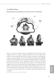
...® LAN chip, ASRock Cloud allows users to remotely wake up their computers, or they could wake up the computer then use Orbweb.ME Professional to remotely wake up and control their computers via the internet by using a secondary device, such as a smartphone or tablet. H81M-VG4 R2.0 3.4 ASRock Cloud ASRock makes your mobile devices connect to your PC on Windows 8.1 or Windows 7. 33 English ASRock Cloud includes several technologies and software solutions...
...® LAN chip, ASRock Cloud allows users to remotely wake up their computers, or they could wake up the computer then use Orbweb.ME Professional to remotely wake up and control their computers via the internet by using a secondary device, such as a smartphone or tablet. H81M-VG4 R2.0 3.4 ASRock Cloud ASRock makes your mobile devices connect to your PC on Windows 8.1 or Windows 7. 33 English ASRock Cloud includes several technologies and software solutions...

User Manual
Page 56
Chapter 4 UEFI SETUP UTILITY 4.1 Introduction ASRock Interactive UEFI is constantly being updated, the following selections: Main For setting system time/date information OC Tweaker For overclocking conigurations Advanced For advanced system conigurations Tool Useful tools H/W Monitor Displays current hardware status Boot For coniguring boot settings and boot priority Security For security settings Exit Exit the current screen or the UEFI Setup Utility 52 English If you wish to conigure your screen. 4.1.1 UEFI Menu Bar he...
Chapter 4 UEFI SETUP UTILITY 4.1 Introduction ASRock Interactive UEFI is constantly being updated, the following selections: Main For setting system time/date information OC Tweaker For overclocking conigurations Advanced For advanced system conigurations Tool Useful tools H/W Monitor Displays current hardware status Boot For coniguring boot settings and boot priority Security For security settings Exit Exit the current screen or the UEFI Setup Utility 52 English If you wish to conigure your screen. 4.1.1 UEFI Menu Bar he...

User Manual
Page 70
... Standby Power down the render unit when the GPU is installed. Set to Auto to enable onboard HD audio and automatically disable it when a sound card is allocated to the integrated graphics processor when the system boots up. Share Memory Conigure the size of memory that is installed. 66 English Onboard HD Audio Enable/disable onboard HD audio. IGPU Multi-Monitor Select disable to keep the integrated graphics enabled at all times. 4.4.2 Chipset Coniguration Primary Graphics Adapter Select a primary VGA.
... Standby Power down the render unit when the GPU is installed. Set to Auto to enable onboard HD audio and automatically disable it when a sound card is allocated to the integrated graphics processor when the system boots up. Share Memory Conigure the size of memory that is installed. 66 English Onboard HD Audio Enable/disable onboard HD audio. IGPU Multi-Monitor Select disable to keep the integrated graphics enabled at all times. 4.4.2 Chipset Coniguration Primary Graphics Adapter Select a primary VGA.

User Manual
Page 71
... the power state ater a power failure. If [Power On] is selected, the power will start to boot up when the power recovers. Good Night LED By enabling Good Night LED, the Power/LAN LEDs will also automatically switch of when the system is shut down. It will be switched of the Power and Keyboard LEDs when the system enters into Standby/Hibernation mode. 67 English Onboard LAN Enable or disable the onboard network interface controller. H81M-VG4 R2.0 Front Panel Enable/disable front panel HD audio.
... the power state ater a power failure. If [Power On] is selected, the power will start to boot up when the power recovers. Good Night LED By enabling Good Night LED, the Power/LAN LEDs will also automatically switch of when the system is shut down. It will be switched of the Power and Keyboard LEDs when the system enters into Standby/Hibernation mode. 67 English Onboard LAN Enable or disable the onboard network interface controller. H81M-VG4 R2.0 Front Panel Enable/disable front panel HD audio.

User Manual
Page 77
...devices (i.e. 4.4.7 USB Coniguration H81M-VG4 R2.0 USB Controller Enable or disable all the USB 3.0 ports. If you encounter USB compatibility issues it . It is recommended to disable legacy USB support. Legacy USB Support Enable or disable Legacy OS Support for USB 3.0 devices. USB mouse or storage) encounter compatibility problems, please enable this option, it is normal that the system will postpone booting up ater pressing the power button. 73 English Please note that ater enabling this option to ix it is recommended to support USB devices under the UEFI setup and Windows...
...devices (i.e. 4.4.7 USB Coniguration H81M-VG4 R2.0 USB Controller Enable or disable all the USB 3.0 ports. If you encounter USB compatibility issues it . It is recommended to disable legacy USB support. Legacy USB Support Enable or disable Legacy OS Support for USB 3.0 devices. USB mouse or storage) encounter compatibility problems, please enable this option, it is normal that the system will postpone booting up ater pressing the power button. 73 English Please note that ater enabling this option to ix it is recommended to support USB devices under the UEFI setup and Windows...
User Manual
Page 79
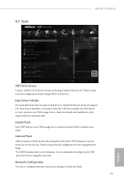
...an USB storage device, then downloads and installs the other required drivers automatically. Network Coniguration Use this function. Easy Driver Installer For users that don't have an optical disk drive to install the drivers from our servers for Internet Flash. 75 English Internet Flash ASRock Internet Flash downloads and updates the latest UEFI irmware version from our support CD, Easy Driver Installer is recommended to update your PC. Please setup network coniguration before using UEFI Tech Service. 4.5 Tools H81M-VG4 R2.0 UEFI Tech Service Contact ASRock Tech Service if...
...an USB storage device, then downloads and installs the other required drivers automatically. Network Coniguration Use this function. Easy Driver Installer For users that don't have an optical disk drive to install the drivers from our servers for Internet Flash. 75 English Internet Flash ASRock Internet Flash downloads and updates the latest UEFI irmware version from our support CD, Easy Driver Installer is recommended to update your PC. Please setup network coniguration before using UEFI Tech Service. 4.5 Tools H81M-VG4 R2.0 UEFI Tech Service Contact ASRock Tech Service if...

Quick Installation Guide
Page 3
Description 1 CPU Fan Connector (CPU_FAN1) 2 2 x 240-pin DDR3 DIMM Slots (DDR3_A1, DDR3_B1) 3 ATX Power Connector (ATXPWR1) 4 System Panel Header (PANEL1) 5 SATA2 Connector (SATA_2) 6 SATA2 Connector (SATA_3) 7 Power LED Header (PLED1) 8 TPM Header (TPMS1) 9 USB 2.0 Header (USB4_5) 10 USB 2.0 Header (USB6_7) 11 SATA3 Connector (SATA_1) 12 SATA3 Connector (SATA_0) 13 Chassis Fan Connector (CHA_FAN1) 14 Chassis Speaker Header (SPEAKER1) 15 Chassis Intrusion Header (CI1) 16 Clear CMOS Jumper (CLRCMOS1) 17 Front Panel Audio Header (HD_AUDIO1) 18 ATX 12V Power Connector (ATX12V1) 2 English No.
Description 1 CPU Fan Connector (CPU_FAN1) 2 2 x 240-pin DDR3 DIMM Slots (DDR3_A1, DDR3_B1) 3 ATX Power Connector (ATXPWR1) 4 System Panel Header (PANEL1) 5 SATA2 Connector (SATA_2) 6 SATA2 Connector (SATA_3) 7 Power LED Header (PLED1) 8 TPM Header (TPMS1) 9 USB 2.0 Header (USB4_5) 10 USB 2.0 Header (USB6_7) 11 SATA3 Connector (SATA_1) 12 SATA3 Connector (SATA_0) 13 Chassis Fan Connector (CHA_FAN1) 14 Chassis Speaker Header (SPEAKER1) 15 Chassis Intrusion Header (CI1) 16 Clear CMOS Jumper (CLRCMOS1) 17 Front Panel Audio Header (HD_AUDIO1) 18 ATX 12V Power Connector (ATX12V1) 2 English No.
Quick Installation Guide
Page 5
...; 2 x Serial ATA (SATA) Data Cables (Optional) • 1 x I/O Panel Shield 4 English It delivers excellent performance with robust design conforming to ASRock's commitment to quality and endurance. Because the motherboard speciications and the BIOS sotware might be updated, the content of this motherboard, please visit our website for purchasing ASRock H81M-VG4 R2.0 motherboard, a reliable motherboard produced under ASRock's consistently stringent quality control. You may ind the latest VGA cards and CPU support list on ASRock...
...; 2 x Serial ATA (SATA) Data Cables (Optional) • 1 x I/O Panel Shield 4 English It delivers excellent performance with robust design conforming to ASRock's commitment to quality and endurance. Because the motherboard speciications and the BIOS sotware might be updated, the content of this motherboard, please visit our website for purchasing ASRock H81M-VG4 R2.0 motherboard, a reliable motherboard produced under ASRock's consistently stringent quality control. You may ind the latest VGA cards and CPU support list on ASRock...

Quick Installation Guide
Page 7
... Speaker / Microphone • 2 x SATA3 6.0 Gb/s Connectors, support NCQ, AHCI and Hot Plug • 2 x SATA2 3.0 Gb/s Connectors, support NCQ, AHCI and Hot Plug • 1 x Power LED Header • 1 x Chassis Intrusion Header • 1 x TPM Header • 1 x CPU Fan Connector (4-pin) • 1 x Chassis Fan Connector (4-pin) • 1 x 24 pin ATX Power Connector • 1 x 4 pin 12V Power Connector • 1 x Front Panel Audio Connector • 2 x USB 2.0 Headers (Support 4 USB 2.0 ports) (Supports ESD Protection (ASRock Full Spike Protection)) • 32Mb AMI UEFI Legal BIOS with...
... Speaker / Microphone • 2 x SATA3 6.0 Gb/s Connectors, support NCQ, AHCI and Hot Plug • 2 x SATA2 3.0 Gb/s Connectors, support NCQ, AHCI and Hot Plug • 1 x Power LED Header • 1 x Chassis Intrusion Header • 1 x TPM Header • 1 x CPU Fan Connector (4-pin) • 1 x Chassis Fan Connector (4-pin) • 1 x 24 pin ATX Power Connector • 1 x 4 pin 12V Power Connector • 1 x Front Panel Audio Connector • 2 x USB 2.0 Headers (Support 4 USB 2.0 ports) (Supports ESD Protection (ASRock Full Spike Protection)) • 32Mb AMI UEFI Legal BIOS with...

Quick Installation Guide
Page 17
... shut it down before you clear the CMOS, the case open may be cleared only if the CMOS battery is placed on CLRCMOS1 for 15 seconds, use a jumper cap to short pin2 and pin3 on these 2 pins. Clear CMOS Jumper (CLRCMOS1) (see p.1, No. 16) Default Clear CMOS CLRCMOS1 allows you update the BIOS. Please adjust the BIOS option "Clear Status" to clear the data in CMOS. 2.5 Jumpers Setup he illustration shows a 3-pin jumper whose pin1 and pin2...
... shut it down before you clear the CMOS, the case open may be cleared only if the CMOS battery is placed on CLRCMOS1 for 15 seconds, use a jumper cap to short pin2 and pin3 on these 2 pins. Clear CMOS Jumper (CLRCMOS1) (see p.1, No. 16) Default Clear CMOS CLRCMOS1 allows you update the BIOS. Please adjust the BIOS option "Clear Status" to clear the data in CMOS. 2.5 Jumpers Setup he illustration shows a 3-pin jumper whose pin1 and pin2...


