User Manual
Page 3
... 1.4 I/O Panel 14 2 Installation 16 2.1 Screw Holes 16 2.2 Pre-installation Precautions 16 2.3 CPU Installation 17 2.4 Installation of Heatsink and CPU fan 19 2.5 Installation of Memory Modules (DIMM 20 2.6 Expansion Slot (PCI Express Slot 21 2.7 Dual Monitor and Surround Display Features 22 2.8 ASRock Smart Remote Installation Guide 25 2.9 Jumpers Setup 26 2.10 Onboard Headers and...
... 1.4 I/O Panel 14 2 Installation 16 2.1 Screw Holes 16 2.2 Pre-installation Precautions 16 2.3 CPU Installation 17 2.4 Installation of Heatsink and CPU fan 19 2.5 Installation of Memory Modules (DIMM 20 2.6 Expansion Slot (PCI Express Slot 21 2.7 Dual Monitor and Surround Display Features 22 2.8 ASRock Smart Remote Installation Guide 25 2.9 Jumpers Setup 26 2.10 Onboard Headers and...
User Manual
Page 4
3 UEFI SETUP UTILITY 36 3.1 Introduction 36 3.1.1 UEFI Menu Bar 36 3.1.2 Navigation Keys 37 3.2 Main Screen 37 3.3 OC Tweaker Screen 38 3.4 Advanced Screen 42 3.4.1 CPU Con guration 43 3.4.2 North Bridge Con guration 45 3.4.3 South Bridge Con guration 46 3.4.4 Storage Con guration 47 3.4.5 Intel(R) Rapid Start Technology 48 3.4.6 Intel(R) Smart Connect ...
3 UEFI SETUP UTILITY 36 3.1 Introduction 36 3.1.1 UEFI Menu Bar 36 3.1.2 Navigation Keys 37 3.2 Main Screen 37 3.3 OC Tweaker Screen 38 3.4 Advanced Screen 42 3.4.1 CPU Con guration 43 3.4.2 North Bridge Con guration 45 3.4.3 South Bridge Con guration 46 3.4.4 Storage Con guration 47 3.4.5 Intel(R) Rapid Start Technology 48 3.4.6 Intel(R) Smart Connect ...
User Manual
Page 5
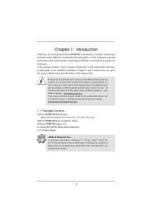
... you for details. 5 You may nd the latest VGA cards and CPU support lists on ASRock website without notice. ASRock website http://www.asrock.com If you require technical support related to AHCI mode. To get ...ASRock H77M-ITX Quick Installation Guide ASRock H77M-ITX Support CD 2 x Serial ATA (SATA) Data Cables (Optional) 1 x I/O Panel Shield ASRock Reminds You... www.asrock.com/support/index.asp 1.1 Package Contents ASRock H77M-ITX Motherboard (Mini-ITX Form Factor: 6.7-in x 6.7-in our support CD for purchasing ASRock H77M-ITX motherboard, a reliable motherboard produced under ASRock...
... you for details. 5 You may nd the latest VGA cards and CPU support lists on ASRock website without notice. ASRock website http://www.asrock.com If you require technical support related to AHCI mode. To get ...ASRock H77M-ITX Quick Installation Guide ASRock H77M-ITX Support CD 2 x Serial ATA (SATA) Data Cables (Optional) 1 x I/O Panel Shield ASRock Reminds You... www.asrock.com/support/index.asp 1.1 Package Contents ASRock H77M-ITX Motherboard (Mini-ITX Form Factor: 6.7-in x 6.7-in our support CD for purchasing ASRock H77M-ITX motherboard, a reliable motherboard produced under ASRock...
User Manual
Page 6
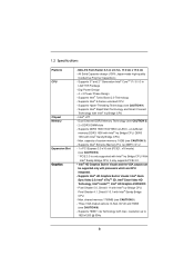
...slot (PCIE1: x16 mode) (see CAUTION 5) - Pixel Shader 5.0, DirectX 11 with Intel® Ivy Bridge CPU. Three VGA Output options: D-Sub, DVI-D and HDMI (see CAUTION 2) - 2 x DDR3 DIMM slots - Mini-ITX Form Factor: 6.7-in x 6.7-in Visuals: Intel® Quick Sync Video 2.0, Intel® InTruTM 3D, Intel... only with processors which are GPU integrated. - Digi Power Design - 4 + 2 Power Phase Design - Supports Intel® K-Series unlocked CPU - Supports Intel® Rapid Start Technology and Smart Connect Technology with max. shared memory 1760MB (see CAUTION 4) * PCIE 3.0 is only ...
...slot (PCIE1: x16 mode) (see CAUTION 5) - Pixel Shader 5.0, DirectX 11 with Intel® Ivy Bridge CPU. Three VGA Output options: D-Sub, DVI-D and HDMI (see CAUTION 2) - 2 x DDR3 DIMM slots - Mini-ITX Form Factor: 6.7-in x 6.7-in Visuals: Intel® Quick Sync Video 2.0, Intel® InTruTM 3D, Intel... only with processors which are GPU integrated. - Digi Power Design - 4 + 2 Power Phase Design - Supports Intel® K-Series unlocked CPU - Supports Intel® Rapid Start Technology and Smart Connect Technology with max. shared memory 1760MB (see CAUTION 4) * PCIE 3.0 is only ...
User Manual
Page 8
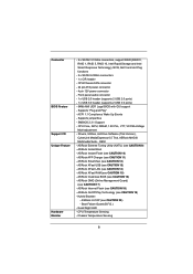
... 3.0 header (supports 2 USB 3.0 ports) - 64Mb AMI UEFI Legal BIOS with GUI support - ASRock Instant Boot - ASRock XFast USB (see CAUTION 15) - ASRock XFast RAM (see CAUTION 13) - ASRock OMG (Online Management Guard) (see CAUTION 20) - ASRock U-COP (see CAUTION 17) - Boot Failure Guard (B.F.G.) - CPU/Chassis FAN connector - 24 pin ATX power connector - 4 pin 12V power connector...
... 3.0 header (supports 2 USB 3.0 ports) - 64Mb AMI UEFI Legal BIOS with GUI support - ASRock Instant Boot - ASRock XFast USB (see CAUTION 15) - ASRock XFast RAM (see CAUTION 13) - ASRock OMG (Online Management Guard) (see CAUTION 20) - ASRock U-COP (see CAUTION 17) - Boot Failure Guard (B.F.G.) - CPU/Chassis FAN connector - 24 pin ATX power connector - 4 pin 12V power connector...
User Manual
Page 9
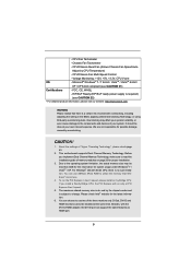
...-bit compliant (see CAUTION 22) * For detailed product information, please visit our website: http://www.asrock.com WARNING Please realize that Windows® cannot use. 4. Before you install a Sandy Bridge CPU, the PCI Express will run the PCI Express in the BIOS, applying Untied Overclocking Technology, or using... on page 20 for system usage under Windows® 7 / VistaTM / XP. For Windows® OS with 64-bit CPU, there is subject to use ASRock XFast RAM to the operating system limitation, the actual memory size may affect your system's stability, or even cause damage to ...
...-bit compliant (see CAUTION 22) * For detailed product information, please visit our website: http://www.asrock.com WARNING Please realize that Windows® cannot use. 4. Before you install a Sandy Bridge CPU, the PCI Express will run the PCI Express in the BIOS, applying Untied Overclocking Technology, or using... on page 20 for system usage under Windows® 7 / VistaTM / XP. For Windows® OS with 64-bit CPU, there is subject to use ASRock XFast RAM to the operating system limitation, the actual memory size may affect your system's stability, or even cause damage to ...
User Manual
Page 10
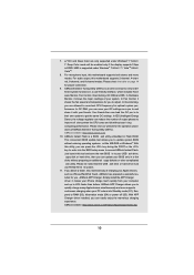
...Saver), the voltage regulator can press the key during the POST or the key to enter into Standby mode (S1), Suspend to overclock CPU frequency for you to quickly charge many Apple devices simultaneously and even supports continuous charging when your computer and up to ne-tune different system...mode will be noted that the USB ash drive or hard drive must use FAT32/16/12 le system. 11. ASRock website: http://www.asrock.com 10. ASRock website: http://www.asrock.com/Feature/AppCharger/index.asp 10 7. xvYCC and Deep Color are idle without entering operating systems rst like MS-...
...Saver), the voltage regulator can press the key during the POST or the key to enter into Standby mode (S1), Suspend to overclock CPU frequency for you to quickly charge many Apple devices simultaneously and even supports continuous charging when your computer and up to ne-tune different system...mode will be noted that the USB ash drive or hard drive must use FAT32/16/12 le system. 11. ASRock website: http://www.asrock.com 10. ASRock website: http://www.asrock.com/Feature/AppCharger/index.asp 10 7. xvYCC and Deep Color are idle without entering operating systems rst like MS-...
User Manual
Page 11
...ideally and/or add new programs. Lower Latency in games. Only USB2.0 ports support this function. 11 In other users. To use ASRock SmartView feature, please make sure your OS version is that helps you are exclusively equipped with friends on the properties of previously visited ...it reduces the frequency of Your Data: With the status window, you must be used under Windows® OS 32-bit CPU. Administrators are required. 18. ASRock motherboards are transferring currently. 15. Please note that combines your most visited web sites, your history, your Facebook friends and ...
...ideally and/or add new programs. Lower Latency in games. Only USB2.0 ports support this function. 11 In other users. To use ASRock SmartView feature, please make sure your OS version is that helps you are exclusively equipped with friends on the properties of previously visited ...it reduces the frequency of Your Data: With the status window, you must be used under Windows® OS 32-bit CPU. Administrators are required. 18. ASRock motherboards are transferring currently. 15. Please note that combines your most visited web sites, your history, your Facebook friends and ...
User Manual
Page 12
...standby power ef ciency should be higher than 50% under 1.00W in ACPI S5 mode)! Before you install the PC system. 21. 19. ASRock On/Off Play Technology allows users to enjoy the great audio experience from the portable audio devices, such like MP3 player or mobile phone to... selection, we recommend you to spray thermal grease between the CPU and the heatsink when you resume the system, please check if the CPU fan on the motherboard functions properly and unplug the power cord, then plug it back again. ASRock XFast RAM is detected, the system will automatically shutdown.
...standby power ef ciency should be higher than 50% under 1.00W in ACPI S5 mode)! Before you install the PC system. 21. 19. ASRock On/Off Play Technology allows users to enjoy the great audio experience from the portable audio devices, such like MP3 player or mobile phone to... selection, we recommend you to spray thermal grease between the CPU and the heatsink when you resume the system, please check if the CPU fan on the motherboard functions properly and unplug the power cord, then plug it back again. ASRock XFast RAM is detected, the system will automatically shutdown.
User Manual
Page 13
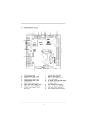
...USB1 Top: B: USB2 RJ-45 Top: CTR BASS Center: REAR SPK Bottom: Optical SPDIF Top: LINE IN Center: FRONT Bottom: MIC IN 1 HD_AUDIO1 AUDIO CODEC H77M-ITX PCIE1 Front USB 3.0 PCI Express 3.0 RoHS 15 1 SPI Flash Memory (64Mb) 2 SATA3 Connector (SATA_1, Gray) 3 SATA3 Connector (SATA_0, Gray) 4 SATA2 ...DIMM Slots (DDR3_A1, DDR3_B1, Black) 12 USB 3.0 Header (USB3_3_4, Black) 13 1155-Pin CPU Socket 14 PCI Express 3.0 x16 Slot (PCIE1, Black) 15 Front Panel Audio Header (HD_AUDIO1, Black) 16 CPU Fan Connector (CPU_FAN1) 17 Chassis Fan Connector (CHA_FAN1) 18 Clear CMOS Jumper (CLRCMOS1) 19...
...USB1 Top: B: USB2 RJ-45 Top: CTR BASS Center: REAR SPK Bottom: Optical SPDIF Top: LINE IN Center: FRONT Bottom: MIC IN 1 HD_AUDIO1 AUDIO CODEC H77M-ITX PCIE1 Front USB 3.0 PCI Express 3.0 RoHS 15 1 SPI Flash Memory (64Mb) 2 SATA3 Connector (SATA_1, Gray) 3 SATA3 Connector (SATA_0, Gray) 4 SATA2 ...DIMM Slots (DDR3_A1, DDR3_B1, Black) 12 USB 3.0 Header (USB3_3_4, Black) 13 1155-Pin CPU Socket 14 PCI Express 3.0 x16 Slot (PCIE1, Black) 15 Front Panel Audio Header (HD_AUDIO1, Black) 16 CPU Fan Connector (CPU_FAN1) 17 Chassis Fan Connector (CHA_FAN1) 18 Clear CMOS Jumper (CLRCMOS1) 19...
User Manual
Page 17
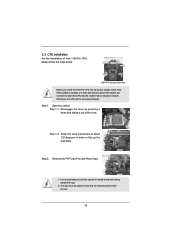
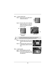
... the PnP cap. 2. Step 1-2. This cap must be seriously damaged. It is recommended to use the cap tab to insert the CPU into the socket, please check if the CPU surface is found. Open the socket: Step 1-1. Disengage the lever by pressing it down and sliding it out of Intel 1155-Pin... CPU, please follow the steps below. Remove the PnP Cap (Pick and Place Cap). 1. Otherwise, the CPU will be placed if returning the motherboard for after service. 17 Keep the lever positioned at about 135...
... the PnP cap. 2. Step 1-2. This cap must be seriously damaged. It is recommended to use the cap tab to insert the CPU into the socket, please check if the CPU surface is found. Open the socket: Step 1-1. Disengage the lever by pressing it down and sliding it out of Intel 1155-Pin... CPU, please follow the steps below. Remove the PnP Cap (Pick and Place Cap). 1. Otherwise, the CPU will be placed if returning the motherboard for after service. 17 Keep the lever positioned at about 135...
User Manual
Page 18
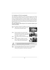
... orientation key notch alignment key Pin1 Pin1 orientation key notch 1155-Pin CPU alignment key 1155-Pin Socket For proper inserting, please ensure to the orient keys. Hold the CPU by using a purely vertical motion. Carefully place the CPU into the socket by the edge which is within the socket and ...properly mated to match the two orientation key notches of the socket. Orient the CPU with the load plate tab under the retention tab. 18 Step 3-3. Press down the load lever, and secure it with the IHS (Integrated...
... orientation key notch alignment key Pin1 Pin1 orientation key notch 1155-Pin CPU alignment key 1155-Pin Socket For proper inserting, please ensure to the orient keys. Hold the CPU by using a purely vertical motion. Carefully place the CPU into the socket by the edge which is within the socket and ...properly mated to match the two orientation key notches of the socket. Orient the CPU with the load plate tab under the retention tab. 18 Step 3-3. Press down the load lever, and secure it with the IHS (Integrated...
User Manual
Page 19
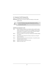
... the fastener clockwise, then press down the fasteners without rotating them clockwise, the heatsink cannot be secured on fastener caps with the CPU fan connector on the socket's surface. Before you install the heatsink, you press down on the motherboard. Apply thermal interface material ... Please adopt the type of heatsink and cooling fan compliant with fan operation or contact other . Step 1. Step 3. 2.4 Installation of CPU Fan and Heatsink This motherboard is an example to illustrate the installation of the heatsink for 1155-Pin CPUs. Step 6. Secure redundant cable ...
... the fastener clockwise, then press down the fasteners without rotating them clockwise, the heatsink cannot be secured on fastener caps with the CPU fan connector on the socket's surface. Before you install the heatsink, you press down on the motherboard. Apply thermal interface material ... Please adopt the type of heatsink and cooling fan compliant with fan operation or contact other . Step 1. Step 3. 2.4 Installation of CPU Fan and Heatsink This motherboard is an example to illustrate the installation of the heatsink for 1155-Pin CPUs. Step 6. Secure redundant cable ...
User Manual
Page 21
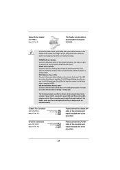
... the documentation of the expansion card and make sure that you start the installation. Align the card connector with screws. If you install a Sandy Bridge CPU, the PCI Express will run the PCI Express in a chassis). PCIE slots:PCIE1 (PCIE 3.0 x16 slot) is completely seated on this motherboard. Keep the screws... is 1 PCI Express slot on the slot. Step 4. 2.6 Expansion Slot (PCI Express Slot) There is already installed in Gen 3 speed, please install an Ivy Bridge CPU. To run only at PCI Express Gen 2 speed.
... the documentation of the expansion card and make sure that you start the installation. Align the card connector with screws. If you install a Sandy Bridge CPU, the PCI Express will run the PCI Express in a chassis). PCIE slots:PCIE1 (PCIE 3.0 x16 slot) is completely seated on this motherboard. Keep the screws... is 1 PCI Express slot on the slot. Step 4. 2.6 Expansion Slot (PCI Express Slot) There is already installed in Gen 3 speed, please install an Ivy Bridge CPU. To run only at PCI Express Gen 2 speed.
User Manual
Page 29
...ground pin. 29 Chassis Fan Connector (4-pin CHA_FAN1) (see p.13, No. 16) FAN_SPEED_CONTROL 4 CPU_FAN_SPEED 3 +12V 2 GND 1 Please connect the CPU fan cable to the connector and match the black wire to turn off (S5). Note the positive and negative pins before connecting the cables. When... the ground pin. A front panel module mainly consists of power switch, reset switch, power LED, hard drive activity LED, speaker and etc. CPU Fan Connectors (4-pin CPU_FAN1) (see p.13, No. 17) FAN_SPEED_CONTROL CHA_FAN_SPEED +12V GND Please connect the chassis fan cable to the connector and ...
...ground pin. 29 Chassis Fan Connector (4-pin CHA_FAN1) (see p.13, No. 16) FAN_SPEED_CONTROL 4 CPU_FAN_SPEED 3 +12V 2 GND 1 Please connect the CPU fan cable to the connector and match the black wire to turn off (S5). Note the positive and negative pins before connecting the cables. When... the ground pin. A front panel module mainly consists of power switch, reset switch, power LED, hard drive activity LED, speaker and etc. CPU Fan Connectors (4-pin CPU_FAN1) (see p.13, No. 17) FAN_SPEED_CONTROL CHA_FAN_SPEED +12V GND Please connect the chassis fan cable to the connector and ...
User Manual
Page 30
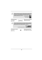
...Connected 3-Pin Fan Installation ATX Power Connector 24 (24-pin ATXPWR1) (see p.13, No. 19) Please connect an ATX 12V power supply to the CPU fan connector on this motherboard, please connect it can work if you adopt a traditional 20-pin ATX power supply. If you plan to connect the... 3-Pin CPU fan to this connector. 30 Though this motherboard provides 4-Pin CPU fan (Quiet Fan) support, the 3-Pin CPU fan still can still work successfully even without the fan speed control function.
...Connected 3-Pin Fan Installation ATX Power Connector 24 (24-pin ATXPWR1) (see p.13, No. 19) Please connect an ATX 12V power supply to the CPU fan connector on this motherboard, please connect it can work if you adopt a traditional 20-pin ATX power supply. If you plan to connect the... 3-Pin CPU fan to this connector. 30 Though this motherboard provides 4-Pin CPU fan (Quiet Fan) support, the 3-Pin CPU fan still can still work successfully even without the fan speed control function.
User Manual
Page 38
...® VistaTM / 7 and want to enable this function, please set this item to [Enabled]. Processors can set this function may reduce CPU voltage and lead to con gure time window which the long duration power is Intel's new power saving technology. This item will be hidden if... The default value is [Enabled]. The default value is [Auto]. If you can switch between multiple frequencies and voltage points to enable/disable CPU Internal PLL Overvoltage Function. Long Duration Power Limit Use this item to enable power saving. Intel Turbo Boost Technology Use this item to run ...
...® VistaTM / 7 and want to enable this function, please set this item to [Enabled]. Processors can set this function may reduce CPU voltage and lead to con gure time window which the long duration power is Intel's new power saving technology. This item will be hidden if... The default value is [Enabled]. The default value is [Auto]. If you can switch between multiple frequencies and voltage points to enable/disable CPU Internal PLL Overvoltage Function. Long Duration Power Limit Use this item to enable power saving. Intel Turbo Boost Technology Use this item to run ...
User Manual
Page 41
...-Line Calibration helps prevent CPU voltage droop when the system is [Auto]. IGPU Voltage Use this to your own requirements. 41 The default value is under heavy load. User Defaults ... helps prevent IGPU voltage droop when the system is [Auto]. The default value is under heavy load. The default is [Enabled]. Voltage Configuration CPU Core Voltage Use this to enable or disable MRC Fast Boot. MRC Fast Boot Use this item to select...
...-Line Calibration helps prevent CPU voltage droop when the system is [Auto]. IGPU Voltage Use this to your own requirements. 41 The default value is under heavy load. User Defaults ... helps prevent IGPU voltage droop when the system is [Auto]. The default value is under heavy load. The default is [Enabled]. Voltage Configuration CPU Core Voltage Use this to enable or disable MRC Fast Boot. MRC Fast Boot Use this item to select...
User Manual
Page 42
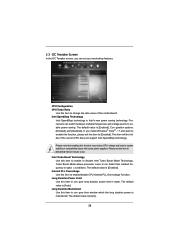
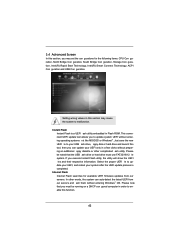
This convenient UEFI update tool allows you to enable this function. 42 Internet Flash Internet Flash searches for the following items: CPU Con guration, North Bridge Con guration, South Bridge Con guration, Storage Con guration, Intel(R) Rapid Start Technology, Intel(R) Smart Connect Technology, ACPI Con guration and ...
This convenient UEFI update tool allows you to enable this function. 42 Internet Flash Internet Flash searches for the following items: CPU Con guration, North Bridge Con guration, South Bridge Con guration, Storage Con guration, Intel(R) Rapid Start Technology, Intel(R) Smart Connect Technology, ACPI Con guration and ...
User Manual
Page 43
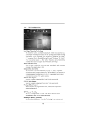
...All processors support the Halt State (C1). In the C1 power state, the processor maintains the context of cores to keep the CPU from the chipset. No-Execute Memory Protection No-Execution (NX) Memory Protection Technology is [All]. Package C State Support Selected ...option will be hidden if the installed CPU does not support Hyper-Threading technology. 3.4.1 CPU Configuration Intel Hyper Threading Technology To enable this feature, a computer system with an Intel processor that supports Hyper...
...All processors support the Halt State (C1). In the C1 power state, the processor maintains the context of cores to keep the CPU from the chipset. No-Execute Memory Protection No-Execution (NX) Memory Protection Technology is [All]. Package C State Support Selected ...option will be hidden if the installed CPU does not support Hyper-Threading technology. 3.4.1 CPU Configuration Intel Hyper Threading Technology To enable this feature, a computer system with an Intel processor that supports Hyper...


