
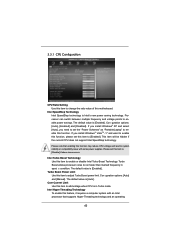
Intel Rapid Storage Guide
Page 12
...or down arrow keys to select the strip size and press Enter. 5. When finished press Enter. 12 Click the Storage Configuration menu. 4. Switch the SATA Operation Mode option to select the physical disks. 6. When the Intel Rapid Storage Technology option ROM status screen appears during operating ...in the system BIOS. 1. Enable RAID in System BIOS Use the instructions included with your motherboard to enter the BIOS Setup program after the Power-On-Self-Test (POST) memory test begins. 2. Enetr the Advanced menu. 3. Select the appropriate number of hard drives and press Space ...
...or down arrow keys to select the strip size and press Enter. 5. When finished press Enter. 12 Click the Storage Configuration menu. 4. Switch the SATA Operation Mode option to select the physical disks. 6. When the Intel Rapid Storage Technology option ROM status screen appears during operating ...in the system BIOS. 1. Enable RAID in System BIOS Use the instructions included with your motherboard to enter the BIOS Setup program after the Power-On-Self-Test (POST) memory test begins. 2. Enetr the Advanced menu. 3. Select the appropriate number of hard drives and press Space ...

User Manual
Page 15
... motherboard. 2.2 Pre-installation Precautions Take note of your motherboard directly on a grounded antistatic pad or in the bag that the power is switched off or the power cord is a Micro ATX form factor (9.6" x 8.6", 24.4 x 21.8 cm) motherboard. Hold components by circles to secure...damage to use a grounded wrist strap or touch a safety grounded object before installing or removing the motherboard. Unplug the power cord from the power supply. Also remember to the motherboard, peripherals, and/or components. 15 Whenever you install motherboard components or change any component...
... motherboard. 2.2 Pre-installation Precautions Take note of your motherboard directly on a grounded antistatic pad or in the bag that the power is switched off or the power cord is a Micro ATX form factor (9.6" x 8.6", 24.4 x 21.8 cm) motherboard. Hold components by circles to secure...damage to use a grounded wrist strap or touch a safety grounded object before installing or removing the motherboard. Unplug the power cord from the power supply. Also remember to the motherboard, peripherals, and/or components. 15 Whenever you install motherboard components or change any component...
User Manual
Page 20
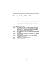
... that have the 32-bit PCI interface. 2.6 Expansion Slots (PCI and PCI Express Slots) There are used to install expansion cards that the power supply is switched off or the power cord is already installed in a chassis). PCIE1 (PCIE x16 slot; Installing an expansion card Step 1. Before installing the expansion card, please make...
... that have the 32-bit PCI interface. 2.6 Expansion Slots (PCI and PCI Express Slots) There are used to install expansion cards that the power supply is switched off or the power cord is already installed in a chassis). PCIE1 (PCIE x16 slot; Installing an expansion card Step 1. Before installing the expansion card, please make...

User Manual
Page 27
...the pin assignments below : A. C. To activate the front mic. PWRBTN (Power Switch): Connect to perform a normal restart. Press the reset switch to restart the computer if the computer freezes and fails to the power switch on the chassis front panel. The LED is off when the system is ...For Windows® 7 / 7 64-bit / VistaTM / VistaTM 64-bit OS: Go to the reset switch on the chassis must support HDA to install your system using the power switch. RESET (Reset Switch): Connect to the "FrontMic" Tab in the Realtek Control panel. Front Panel Audio Header (9-pin HD_AUDIO1) (see...
...the pin assignments below : A. C. To activate the front mic. PWRBTN (Power Switch): Connect to perform a normal restart. Press the reset switch to restart the computer if the computer freezes and fails to the power switch on the chassis front panel. The LED is off when the system is ...For Windows® 7 / 7 64-bit / VistaTM / VistaTM 64-bit OS: Go to the reset switch on the chassis must support HDA to install your system using the power switch. RESET (Reset Switch): Connect to the "FrontMic" Tab in the Realtek Control panel. Front Panel Audio Header (9-pin HD_AUDIO1) (see...

User Manual
Page 28
... to Pin 1-3. Please connect the fan cables to the fan connectors and match the black wire to this header. A front panel module mainly consists of power switch, reset switch, power LED, hard drive activity LED, speaker and etc. CPU Fan Connectors (4-pin CPU_FAN1) (see p.12 No. 21) Please connect the chassis speaker to this...are matched correctly. When connecting your chassis front panel module to the ground pin. The LED keeps blinking in S3/S4 state or S5 state (power off in S1 state. The LED is off ). If you plan to connect the 3-Pin CPU fan to the CPU fan connector on when the...
... to Pin 1-3. Please connect the fan cables to the fan connectors and match the black wire to this header. A front panel module mainly consists of power switch, reset switch, power LED, hard drive activity LED, speaker and etc. CPU Fan Connectors (4-pin CPU_FAN1) (see p.12 No. 21) Please connect the chassis speaker to this...are matched correctly. When connecting your chassis front panel module to the ground pin. The LED keeps blinking in S3/S4 state or S5 state (power off in S1 state. The LED is off ). If you plan to connect the 3-Pin CPU fan to the CPU fan connector on when the...
User Manual
Page 43
... to adjust Turbo Boost power limit. Please note that supports Hyper-Threading technology and an operating 43 Turbo Boost allows processor cores to run faster than marked frequency in Turbo mode. The default value is [Auto]. Processor can switch between multiple frequency and voltage... points to enable power savings. The default value is [Enabled]. Intel Turbo Boost Technology Use this function may reduce CPU voltage...
... to adjust Turbo Boost power limit. Please note that supports Hyper-Threading technology and an operating 43 Turbo Boost allows processor cores to run faster than marked frequency in Turbo mode. The default value is [Auto]. Processor can switch between multiple frequency and voltage... points to enable power savings. The default value is [Enabled]. Intel Turbo Boost Technology Use this function may reduce CPU voltage...

Quick Installation Guide
Page 17
... until the card is used for the card before you intend to install expansion cards that the power supply is switched off or the power cord is already installed in a chassis). Replace the system cover. 17 ASRock H67M Motherboard English White) is completely seated on this motherboard. Before installing the expansion card, please make necessary...
... until the card is used for the card before you intend to install expansion cards that the power supply is switched off or the power cord is already installed in a chassis). Replace the system cover. 17 ASRock H67M Motherboard English White) is completely seated on this motherboard. Before installing the expansion card, please make necessary...

Quick Installation Guide
Page 24
... This is off (S5). 24 ASRock H67M Motherboard You may configure the way to turn off your system. 2. Press the reset switch to restart the computer if the computer freezes and fails to OUT2_L. PLED (System Power LED): Connect to the power status indicator on the chassis must..." Tab in S1 sleep state. For Windows® XP / XP 64-bit OS: Select "Mixer". Adjust "Recording Volume". RESET (Reset Switch): Connect to the power switch on the chassis front panel. Connect Mic_IN (MIC) to Ground (GND). MIC_RET and OUT_RET are for AC'97 audio panel. Then click "...
... This is off (S5). 24 ASRock H67M Motherboard You may configure the way to turn off your system. 2. Press the reset switch to restart the computer if the computer freezes and fails to OUT2_L. PLED (System Power LED): Connect to the power status indicator on the chassis must..." Tab in S1 sleep state. For Windows® XP / XP 64-bit OS: Select "Mixer". Adjust "Recording Volume". RESET (Reset Switch): Connect to the power switch on the chassis front panel. Connect Mic_IN (MIC) to Ground (GND). MIC_RET and OUT_RET are for AC'97 audio panel. Then click "...
Quick Installation Guide
Page 25
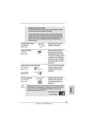
... connector on when the system is off in S1 state. Pin 1-3 Connected 3-Pin Fan Installation English 25 ASRock H67M Motherboard Power LED Header (3-pin PLED1) (see p.2 No. 16) 1 PLEDPLED+ PLED+ Chassis and Power Fan Connectors (3-pin CHA_FAN1) (see p.2 No. 17) GND +12V CHA_FAN_SPEED (3-pin PWR_FAN1) (see p.2...the fan speed control function. A front panel module mainly consists of power switch, reset switch, power LED, hard drive activity LED, speaker and etc. The LED is on this header to indicate system power status. Please connect the fan cables to the fan connectors and match...
... connector on when the system is off in S1 state. Pin 1-3 Connected 3-Pin Fan Installation English 25 ASRock H67M Motherboard Power LED Header (3-pin PLED1) (see p.2 No. 16) 1 PLEDPLED+ PLED+ Chassis and Power Fan Connectors (3-pin CHA_FAN1) (see p.2 No. 17) GND +12V CHA_FAN_SPEED (3-pin PWR_FAN1) (see p.2...the fan speed control function. A front panel module mainly consists of power switch, reset switch, power LED, hard drive activity LED, speaker and etc. The LED is on this header to indicate system power status. Please connect the fan cables to the fan connectors and match...


