Intel Rapid Storage Guide
Page 13
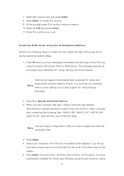
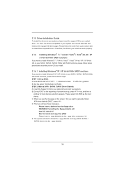
... the Note necessary files. 4. Install the RAID Driver Using the F6 Installation Method Perform the following files: IAAHCI.INF, IAAHCI.CAT, IASTOR.INF, IASTOR.CAT, IASTOR.SYS, and TXTSETUP.OEM. This message appears at the beginning of available SCSI adapters. Use the Floppy Configuration Utility to create a floppy disk with a screen asking you need to confirm your controller from the list of Windows XP* setup (during operating system...
... the Note necessary files. 4. Install the RAID Driver Using the F6 Installation Method Perform the following files: IAAHCI.INF, IAAHCI.CAT, IASTOR.INF, IASTOR.CAT, IASTOR.SYS, and TXTSETUP.OEM. This message appears at the beginning of available SCSI adapters. Use the Floppy Configuration Utility to create a floppy disk with a screen asking you need to confirm your controller from the list of Windows XP* setup (during operating system...

User Manual
Page 3
...Motherboard Layout 12 1.4 I/O Panel 13 2 Installation 15 2.1 Screw Holes 15 2.2 Pre-installation Precautions 15 2.3 CPU Installation 16 2.4 Installation of Heatsink and CPU fan 18 2.5 Installation of Memory Modules (DIMM 19 2.6 Expansion Slots (PCI and PCI Express Slots 20 2.7 Dual Monitor and Surround Display Features 21 2.9 Jumpers Setup 24 2.9 Onboard Headers and Connectors 25 2.10 Serial ATA (SATA) / Serial ATAII (SATAII) Hard Disks Installation 30 2.11 Serial ATA3 (SATA3) Hard Disks Installation 30 2.12 Hot Plug and Hot Swap Functions for SATA / SATAII HDDs 31 2.13 Hot Plug...
...Motherboard Layout 12 1.4 I/O Panel 13 2 Installation 15 2.1 Screw Holes 15 2.2 Pre-installation Precautions 15 2.3 CPU Installation 16 2.4 Installation of Heatsink and CPU fan 18 2.5 Installation of Memory Modules (DIMM 19 2.6 Expansion Slots (PCI and PCI Express Slots 20 2.7 Dual Monitor and Surround Display Features 21 2.9 Jumpers Setup 24 2.9 Onboard Headers and Connectors 25 2.10 Serial ATA (SATA) / Serial ATAII (SATAII) Hard Disks Installation 30 2.11 Serial ATA3 (SATA3) Hard Disks Installation 30 2.12 Hot Plug and Hot Swap Functions for SATA / SATAII HDDs 31 2.13 Hot Plug...

User Manual
Page 9
... press key to BIOS setup menu to overclock CPU frequency for proper installation. 3. In Fan Control, it shows the major readings of the three monitors only. Please visit our website for proper connection. 8. Just launch this utility, you to use two of your friends. CAUTION! 1. Deep Color mode will be enabled at the same time. Please check Intel® website for you implement Dual Channel Memory Technology, make sure to -HDMI...
... press key to BIOS setup menu to overclock CPU frequency for proper installation. 3. In Fan Control, it shows the major readings of the three monitors only. Please visit our website for proper connection. 8. Just launch this utility, you to use two of your friends. CAUTION! 1. Deep Color mode will be enabled at the same time. Please check Intel® website for you implement Dual Channel Memory Technology, make sure to -HDMI...
User Manual
Page 12
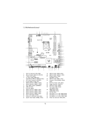
... Power Connector (ATX12V1) 3 1155-Pin CPU Socket 4 2 x 240-pin DDR3 DIMM Slots (Dual Channel: DDR3_A1, DDR3_B1, Blue) 5 ATX Power Connector (ATXPWR1) 6 Infrared Module Header (IR1) 7 SATA3 Connector (SATA3_0, White) 8 SATA3 Connector (SATA3_1, White) 9 Clear CMOS Jumper (CLRCMOS1) 10 64Mb SPI Flash 11 Intel H67 Chipset 12 SATA2 Connector (SATA2_3, Blue) 13 SATA2 Connector (SATA2_2, Blue) 14 SATA2 Connector (SATA2_4, Blue) 15 SATA2 Connector (SATA2_5, Blue) 16 Power LED Header (PLED1) 17 Chassis Fan Connector (CHA_FAN1) 18 System Panel Header (PANEL1, White) 19 USB 2.0 Header...
... Power Connector (ATX12V1) 3 1155-Pin CPU Socket 4 2 x 240-pin DDR3 DIMM Slots (Dual Channel: DDR3_A1, DDR3_B1, Blue) 5 ATX Power Connector (ATXPWR1) 6 Infrared Module Header (IR1) 7 SATA3 Connector (SATA3_0, White) 8 SATA3 Connector (SATA3_1, White) 9 Clear CMOS Jumper (CLRCMOS1) 10 64Mb SPI Flash 11 Intel H67 Chipset 12 SATA2 Connector (SATA2_3, Blue) 13 SATA2 Connector (SATA2_2, Blue) 14 SATA2 Connector (SATA2_4, Blue) 15 SATA2 Connector (SATA2_5, Blue) 16 Power LED Header (PLED1) 17 Chassis Fan Connector (CHA_FAN1) 18 System Panel Header (PANEL1, White) 19 USB 2.0 Header...

User Manual
Page 21
... computer. You can drive same or different display contents. Connect DVI-D monitor cable to VGA/DVI-D port on the I/O panel, connect D-Sub monitor cable to VGA/D-Sub port on the I/O panel, or connect HDMI monitor cable to HDMI port on VGA card to your system and restart your system boots. To enable dual monitor feature, please follow the below steps: 1. 2.7 Dual Monitor and Surround Display Features Dual Monitor Feature This motherboard supports dual monitor feature. If you haven't installed onboard VGA driver yet, please install onboard VGA driver from our support CD to your...
... computer. You can drive same or different display contents. Connect DVI-D monitor cable to VGA/DVI-D port on the I/O panel, connect D-Sub monitor cable to VGA/D-Sub port on the I/O panel, or connect HDMI monitor cable to HDMI port on VGA card to your system and restart your system boots. To enable dual monitor feature, please follow the below steps: 1. 2.7 Dual Monitor and Surround Display Features Dual Monitor Feature This motherboard supports dual monitor feature. If you haven't installed onboard VGA driver yet, please install onboard VGA driver from our support CD to your...

User Manual
Page 22
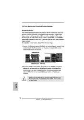
Surround Display Feature This motherboard supports surround display upgrade. With the internal VGA output support (DVI-D, D-Sub and HDMI) and external add-on PCI Express VGA cards, you can adjust the parameters of the add-on PCI Express VGA card on PCI Express VGA card driver to your system. Install the PCI Express VGA card on the I/O panel. Boot your system. If you can easily enjoy the bene ts of "Onboard VGA Share Memory", [Auto], will be Primary, and all additional monitors will disable VGA/D-Sub function...
Surround Display Feature This motherboard supports surround display upgrade. With the internal VGA output support (DVI-D, D-Sub and HDMI) and external add-on PCI Express VGA cards, you can adjust the parameters of the add-on PCI Express VGA card on PCI Express VGA card driver to your system. Install the PCI Express VGA card on the I/O panel. Boot your system. If you can easily enjoy the bene ts of "Onboard VGA Share Memory", [Auto], will be Primary, and all additional monitors will disable VGA/D-Sub function...
User Manual
Page 34
... SATA / SATAII / SATA3 HDDs with RAID functions, please follow below steps. Enter BIOS SETUP UTILITY Advanced screen SATA Con guration. Then, the drivers compatible to your SATA / SATAII / SATA3 HDDs with RAID functions, please follow the order from up to bottom side to boot your optical drive rst. Therefore, the drivers you install can be auto-detected and listed on your system can work properly. 2.16 Installing Windows® 7 / 7 64-bit / VistaTM / VistaTM 64-bit...
... SATA / SATAII / SATA3 HDDs with RAID functions, please follow below steps. Enter BIOS SETUP UTILITY Advanced screen SATA Con guration. Then, the drivers compatible to your SATA / SATAII / SATA3 HDDs with RAID functions, please follow the order from up to bottom side to boot your optical drive rst. Therefore, the drivers you install can be auto-detected and listed on your system can work properly. 2.16 Installing Windows® 7 / 7 64-bit / VistaTM / VistaTM 64-bit...

User Manual
Page 35
... Support CD, "Guide to SATA Hard Disks Installation and RAID Con guration", which is located in the folder at the following path: .. \ RAID Installation Guide and the document in the support CD, "Guide to Intel Rapid Storage", which is located in Windows® environment, please install "SATAII driver" from the installation CD. 4. The following path: .. \ RAID Installation Guide STEP 4: Install Windows® XP / XP 64-bit OS on your system. At the beginning of Windows® setup...
... Support CD, "Guide to SATA Hard Disks Installation and RAID Con guration", which is located in the folder at the following path: .. \ RAID Installation Guide and the document in the support CD, "Guide to Intel Rapid Storage", which is located in Windows® environment, please install "SATAII driver" from the installation CD. 4. The following path: .. \ RAID Installation Guide STEP 4: Install Windows® XP / XP 64-bit OS on your system. At the beginning of Windows® setup...

User Manual
Page 36
... the serial number of the next section to migrate the system to RAID 0, RAID 1 or RAID 5. 2.16.3 Migrating a "RAID Ready" System to extend any data on the destination hard drive will need another SATA / SATAII hard drive with your motherboard or after downloading it as prompted. Boot Windows®, install the Intel(R) Rapid Storage software, if not already installed, using the setup package obtained from a CD-ROM or from Existing Hard Drive Wizard...
... the serial number of the next section to migrate the system to RAID 0, RAID 1 or RAID 5. 2.16.3 Migrating a "RAID Ready" System to extend any data on the destination hard drive will need another SATA / SATAII hard drive with your motherboard or after downloading it as prompted. Boot Windows®, install the Intel(R) Rapid Storage software, if not already installed, using the setup package obtained from a CD-ROM or from Existing Hard Drive Wizard...
User Manual
Page 37
... installed to your system. B. STEP 2: Use "RAID Installation Guide" to [RAID]. Please refer to the document in the Support CD, "Guide to SATA Hard Disks Installation and RAID Con guration", which is located in the folder at the following path: .. \ Intel Rapid Storage Information If you need to use both "RAID Installation Guide" and "Intel Rapid Storage Information" for proper con guration. Enter BIOS SETUP UTILITY Advanced screen SATA Con guration. After the installation of Windows® 7 / 7 64-bit...
... installed to your system. B. STEP 2: Use "RAID Installation Guide" to [RAID]. Please refer to the document in the Support CD, "Guide to SATA Hard Disks Installation and RAID Con guration", which is located in the folder at the following path: .. \ Intel Rapid Storage Information If you need to use both "RAID Installation Guide" and "Intel Rapid Storage Information" for proper con guration. Enter BIOS SETUP UTILITY Advanced screen SATA Con guration. After the installation of Windows® 7 / 7 64-bit...

User Manual
Page 52
... enable or disable the onboard serial port. Con guration options: [Auto], [3F8 / IRQ4], [2F8 / IRQ3], [3E8 / IRQ4], [2E8 / IRQ3]. Change Settings Use this item to change the Printer Port mode. 52 Device Mode Use this item to select an optional setting for Super IO device. 3.3.8 Super IO Configuration OnBoard Floppy Controller Use this item to enable or disable the onboard parallel port. Con guration options: [Auto], [3F8 / IRQ4], [2F8 / IRQ3], [3E8 / IRQ4], [2E8 / IRQ3]. Parallel Port Use this item to enable or disable oppy drive controller...
... enable or disable the onboard serial port. Con guration options: [Auto], [3F8 / IRQ4], [2F8 / IRQ3], [3E8 / IRQ4], [2E8 / IRQ3]. Change Settings Use this item to change the Printer Port mode. 52 Device Mode Use this item to select an optional setting for Super IO device. 3.3.8 Super IO Configuration OnBoard Floppy Controller Use this item to enable or disable the onboard parallel port. Con guration options: [Auto], [3F8 / IRQ4], [2F8 / IRQ3], [3E8 / IRQ4], [2E8 / IRQ3]. Parallel Port Use this item to enable or disable oppy drive controller...
User Manual
Page 55
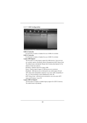
... for legacy USB. [Auto] - Enables support for the details of these four options: [Enabled] - The default value is [Enabled]. There are connected. [Disabled] - USB devices are allowed to use of USB 2.0 controller. Legacy USB 3.0 Support Use this item to enable or disable the use under UEFI setup and Windows / Linux OS. USB devices are not allowed to use of USB 3.0 controller. If you have USB compatibility issue, it is selected. 3.3.11 USB Configuration USB 2.0 Controller Use this option to enable or disable legacy support for USB 3.0 devices. Legacy USB Support Use this...
... for legacy USB. [Auto] - Enables support for the details of these four options: [Enabled] - The default value is [Enabled]. There are connected. [Disabled] - USB devices are allowed to use of USB 2.0 controller. Legacy USB 3.0 Support Use this item to enable or disable the use under UEFI setup and Windows / Linux OS. USB devices are not allowed to use of USB 3.0 controller. If you have USB compatibility issue, it is selected. 3.3.11 USB Configuration USB 2.0 Controller Use this option to enable or disable legacy support for USB 3.0 devices. Legacy USB Support Use this...
User Manual
Page 60
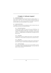
....asrock.com; Because motherboard settings and hardware options vary, use the setup procedures in the Support CD to activate the devices. 4.2.3 Utilities Menu The Utilities Menu shows the applications software that enhance the motherboard features. 4.2.1 Running The Support CD To begin using the support CD, insert the CD into your computer. The CD automatically displays the Main Menu if "AUTORUN" is enabled in your CD-ROM drive. Please install the necessary drivers to display the menus. 4.2.2 Drivers Menu...
....asrock.com; Because motherboard settings and hardware options vary, use the setup procedures in the Support CD to activate the devices. 4.2.3 Utilities Menu The Utilities Menu shows the applications software that enhance the motherboard features. 4.2.1 Running The Support CD To begin using the support CD, insert the CD into your computer. The CD automatically displays the Main Menu if "AUTORUN" is enabled in your CD-ROM drive. Please install the necessary drivers to display the menus. 4.2.2 Drivers Menu...

Quick Installation Guide
Page 2
... Power Connector (ATX12V1) 3 1155-Pin CPU Socket 4 2 x 240-pin DDR3 DIMM Slots (Dual Channel: DDR3_A1, DDR3_B1, Blue) 5 ATX Power Connector (ATXPWR1) 6 Infrared Module Header (IR1) 7 SATA3 Connector (SATA3_0, White) 8 SATA3 Connector (SATA3_1, White) 9 Clear CMOS Jumper (CLRCMOS1) 10 64Mb SPI Flash 11 Intel H67 Chipset 12 SATA2 Connector (SATA2_3, Blue) 13 SATA2 Connector (SATA2_2, Blue) 14 SATA2 Connector (SATA2_4, Blue) 15 SATA2 Connector (SATA2_5, Blue) 16 Power LED Header (PLED1) 17 Chassis Fan Connector (CHA_FAN1) 18 System Panel Header (PANEL1, White) 19 USB 2.0 Header...
... Power Connector (ATX12V1) 3 1155-Pin CPU Socket 4 2 x 240-pin DDR3 DIMM Slots (Dual Channel: DDR3_A1, DDR3_B1, Blue) 5 ATX Power Connector (ATXPWR1) 6 Infrared Module Header (IR1) 7 SATA3 Connector (SATA3_0, White) 8 SATA3 Connector (SATA3_1, White) 9 Clear CMOS Jumper (CLRCMOS1) 10 64Mb SPI Flash 11 Intel H67 Chipset 12 SATA2 Connector (SATA2_3, Blue) 13 SATA2 Connector (SATA2_2, Blue) 14 SATA2 Connector (SATA2_4, Blue) 15 SATA2 Connector (SATA2_5, Blue) 16 Power LED Header (PLED1) 17 Chassis Fan Connector (CHA_FAN1) 18 System Panel Header (PANEL1, White) 19 USB 2.0 Header...
Quick Installation Guide
Page 8
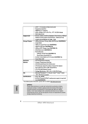
...see CAUTION 8) - CPU Fan Multi-Speed Control - ACPI 1.1 Compliance Wake Up Events - IGPU, DRAM, PCH, CPU PLL, VTT, VCCSA Voltage Multi-adjustment Support CD - ASRock Extreme Tuning Utility (AXTU) (see CAUTION 12) - Instant Boot - Combo Cooler Option (C.C.O.) (see CAUTION 10) - CPU/Chassis/Power Fan Tachometer - CPU/Chassis Quiet Fan (Allow Chassis Fan Speed Auto-Adjust by overclocking. FCC, CE, WHQL - Drivers, Utilities, AntiVirus Software (Trial Version), ASRock Software Suite (CyberLink DVD Suite - Boot Failure Guard (B.F.G.) - Overclocking may affect your...
...see CAUTION 8) - CPU Fan Multi-Speed Control - ACPI 1.1 Compliance Wake Up Events - IGPU, DRAM, PCH, CPU PLL, VTT, VCCSA Voltage Multi-adjustment Support CD - ASRock Extreme Tuning Utility (AXTU) (see CAUTION 12) - Instant Boot - Combo Cooler Option (C.C.O.) (see CAUTION 10) - CPU/Chassis/Power Fan Tachometer - CPU/Chassis Quiet Fan (Allow Chassis Fan Speed Auto-Adjust by overclocking. FCC, CE, WHQL - Drivers, Utilities, AntiVirus Software (Trial Version), ASRock Software Suite (CyberLink DVD Suite - Boot Failure Guard (B.F.G.) - Overclocking may affect your...
Quick Installation Guide
Page 9
.... In Hardware Monitor, it shows the fan speed and temperature for you implement Dual Channel Memory Technology, make sure to use two of memory modules on page 3 for the latest information. 5. For audio output, this motherboard supports both stereo and mono modes. This convenient BIOS update tool allows you can press key during the POST or press key to BIOS setup menu to change. xvYCC and Deep Color are idle without entering operating systems...
.... In Hardware Monitor, it shows the fan speed and temperature for you implement Dual Channel Memory Technology, make sure to use two of memory modules on page 3 for the latest information. 5. For audio output, this motherboard supports both stereo and mono modes. This convenient BIOS update tool allows you can press key during the POST or press key to BIOS setup menu to change. xvYCC and Deep Color are idle without entering operating systems...
Quick Installation Guide
Page 18
... I /O panel. With the internal VGA output support (DVI-D, D-Sub and HDMI), you can drive same or different display contents. Connect DVI-D monitor cable to VGA/DVI-D port on the I/O panel, connect D-Sub monitor cable to VGA/D-Sub port on VGA card to your system and restart your system boots. You can easily enjoy the benefits of dual monitor function after your computer. If you have installed onboard VGA driver from our support CD to this motherboard. To enable dual monitor...
... I /O panel. With the internal VGA output support (DVI-D, D-Sub and HDMI), you can drive same or different display contents. Connect DVI-D monitor cable to VGA/DVI-D port on the I/O panel, connect D-Sub monitor cable to VGA/D-Sub port on VGA card to your system and restart your system boots. You can easily enjoy the benefits of dual monitor function after your computer. If you have installed onboard VGA driver from our support CD to this motherboard. To enable dual monitor...

Quick Installation Guide
Page 19
... PCI Express VGA cards, you do not adjust the BIOS setup, the default value of the multi-monitor according to the steps below. G. Boot your card, one , two, three and four 19 ASRock H67M Motherboard English Set up a surround display environment: 1. D. With the internal VGA output support (DVI-D, D-Sub and HDMI) and external add-on each monitor. Please refer to the following steps to HDMI port on the I /O panel. C. Surround Display Feature This motherboard supports surround display upgrade. Connect...
... PCI Express VGA cards, you do not adjust the BIOS setup, the default value of the multi-monitor according to the steps below. G. Boot your card, one , two, three and four 19 ASRock H67M Motherboard English Set up a surround display environment: 1. D. With the internal VGA output support (DVI-D, D-Sub and HDMI) and external add-on each monitor. Please refer to the following steps to HDMI port on the I /O panel. C. Surround Display Feature This motherboard supports surround display upgrade. Connect...
Quick Installation Guide
Page 29
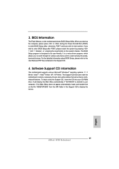
... BIOS Setup Utility. The BIOS Setup program is a menu-driven program, which allows you wish to display the menus. 29 ASRock H67M Motherboard English If you to scroll through its test routines. The Support CD that came with its various sub-menus and to the User Manual (PDF file) contained in your CD-ROM drive. Software Support CD information This motherboard supports various Microsoft® Windows® operating systems: 7 / 7 64-bit...
... BIOS Setup Utility. The BIOS Setup program is a menu-driven program, which allows you wish to display the menus. 29 ASRock H67M Motherboard English If you to scroll through its test routines. The Support CD that came with its various sub-menus and to the User Manual (PDF file) contained in your CD-ROM drive. Software Support CD information This motherboard supports various Microsoft® Windows® operating systems: 7 / 7 64-bit...
RAID Installation Guide
Page 7
... RAID configuration. The following path: .. \ RAID Installation Guide and the document in the support CD, "Guide to Intel Rapid Storage", which is located in the folder at a later date by booting from the Support CD again so that "Intel Rapid Storage" will be presented. When done, exit Setup. 3. Select the driver to install according to install Windows® XP / XP 64-bit on your system. After reading the floppy disk...
... RAID configuration. The following path: .. \ RAID Installation Guide and the document in the support CD, "Guide to Intel Rapid Storage", which is located in the folder at a later date by booting from the Support CD again so that "Intel Rapid Storage" will be presented. When done, exit Setup. 3. Select the driver to install according to install Windows® XP / XP 64-bit on your system. After reading the floppy disk...


