
User Manual
Page 4
... 41 3.1 Introduction 41 3.1.1 UEFI Menu Bar 41 3.1.2 Navigation Keys 42 3.2 Main Screen 42 3.3 Advanced Screen 43 3.3.1 CPU Con guration 44 3.3.2 Intel IGD SWSCI OpRegion Con guration........... 46 3.3.3 Integrated Clock ...
... 41 3.1 Introduction 41 3.1.1 UEFI Menu Bar 41 3.1.2 Navigation Keys 42 3.2 Main Screen 42 3.3 Advanced Screen 43 3.3.1 CPU Con guration 44 3.3.2 Intel IGD SWSCI OpRegion Con guration........... 46 3.3.3 Integrated Clock ...

User Manual
Page 7
... Ef cient Ethernet 802.3az I /O SATA3 USB3.0 Connector BIOS Feature - CPU/Chassis/Power FAN connector - 24 pin ATX power connector - 8 pin 12V power connector - AMI UEFI Legal BIOS with LED (ACT/LINK LED and SPEED LED) - Supports "Plug and Play" 7 Supports Wake-On-LAN - LAN Rear Panel I /O Panel - 1 x PS/2 Keyboard Port...
... Ef cient Ethernet 802.3az I /O SATA3 USB3.0 Connector BIOS Feature - CPU/Chassis/Power FAN connector - 24 pin ATX power connector - 8 pin 12V power connector - AMI UEFI Legal BIOS with LED (ACT/LINK LED and SPEED LED) - Supports "Plug and Play" 7 Supports Wake-On-LAN - LAN Rear Panel I /O Panel - 1 x PS/2 Keyboard Port...

User Manual
Page 41
... is constantly being updated, the following selections: Main To set up the system time/date information Advanced To set up the advanced UEFI features H/W Monitor To display current hardware status Boot To set up the default system device to locate and load the Operating System Security To set ...up the computer. You may run the UEFI SETUP UTILITY when you see on your screen. 3.1.1 UEFI Menu Bar The top of the screen has a menu bar with its test routines. You can also use the...
... is constantly being updated, the following selections: Main To set up the system time/date information Advanced To set up the advanced UEFI features H/W Monitor To display current hardware status Boot To set up the default system device to locate and load the Operating System Security To set ...up the computer. You may run the UEFI SETUP UTILITY when you see on your screen. 3.1.1 UEFI Menu Bar The top of the screen has a menu bar with its test routines. You can also use the...

User Manual
Page 42
... UTILITY To jump to the Exit Screen or exit the current screen 3.2 Main Screen When you enter the UEFI SETUP UTILITY, the Main screen will appear and display the system overview. 42 Navigation Key(s) Function Description / / + / Moves cursor left or right to select Screens ...
... UTILITY To jump to the Exit Screen or exit the current screen 3.2 Main Screen When you enter the UEFI SETUP UTILITY, the Main screen will appear and display the system overview. 42 Navigation Key(s) Function Description / / + / Moves cursor left or right to select Screens ...

User Manual
Page 43
...16/12 le system. 3.3 Advanced Screen In this section, you execute ASRock Instant Flash utility, the utility will show the UEFI les and their respective information. Select the proper UEFI le to update your UEFI, and reboot your UEFI only in a few clicks without entering operating systems rst like MS-.... Setting wrong values in Flash ROM. ASRock Instant Flash ASRock Instant Flash is a UEFI flash utility embedded in this tool and save the new UEFI le to your USB ash drive, oppy disk or hard drive, then you to malfunction. This convenient UEFI update tool allows you can update your...
...16/12 le system. 3.3 Advanced Screen In this section, you execute ASRock Instant Flash utility, the utility will show the UEFI les and their respective information. Select the proper UEFI le to update your UEFI, and reboot your UEFI only in a few clicks without entering operating systems rst like MS-.... Setting wrong values in Flash ROM. ASRock Instant Flash ASRock Instant Flash is a UEFI flash utility embedded in this tool and save the new UEFI le to your USB ash drive, oppy disk or hard drive, then you to malfunction. This convenient UEFI update tool allows you can update your...

User Manual
Page 56
... use of USB 2.0 controller. The default value is [Enabled]. 56 Enables legacy support if USB devices are four con guration options: [Enabled], [Auto], [Disabled] and [UEFI Setup Only]. The default value is [Enabled]. 3.3.11 USB Configuration USB 2.0 Controller Use this item to select legacy support for USB devices. Legacy USB 3.0 Support...USB. [Auto] - USB devices are allowed to use of these four options: [Enabled] - USB devices are not allowed to use only under legacy OS and UEFI setup when [Disabled] is recommended to select [Disabled] to enable or disable the use under...
... use of USB 2.0 controller. The default value is [Enabled]. 56 Enables legacy support if USB devices are four con guration options: [Enabled], [Auto], [Disabled] and [UEFI Setup Only]. The default value is [Enabled]. 3.3.11 USB Configuration USB 2.0 Controller Use this item to select legacy support for USB devices. Legacy USB 3.0 Support...USB. [Auto] - USB devices are allowed to use of these four options: [Enabled] - USB devices are not allowed to use only under legacy OS and UEFI setup when [Disabled] is recommended to select [Disabled] to enable or disable the use under...

User Manual
Page 60
...changes and exit setup?" Discard Changes and Exit When you are allowed to load and save the changes and exit the UEFI SETUP UTILITY. Load UEFI Defaults Load UEFI default values for this operation. Launch EFI Shell from one of the available lesystem devices. 60 Select [OK] to Launch... EFI Shell application (Shell64.efi) from filesystem device Attempts to exit the UEFI SETUP UTILITY without saving any changes. Discard Changes When you select this option, you select this option, it will pop-out the following ...
...changes and exit setup?" Discard Changes and Exit When you are allowed to load and save the changes and exit the UEFI SETUP UTILITY. Load UEFI Defaults Load UEFI default values for this operation. Launch EFI Shell from one of the available lesystem devices. 60 Select [OK] to Launch... EFI Shell application (Shell64.efi) from filesystem device Attempts to exit the UEFI SETUP UTILITY without saving any changes. Discard Changes When you select this option, you select this option, it will pop-out the following ...
User Manual
Page 62
... Utility > Boot > Boot Option #1. ("xxx" is adopting UEFI BIOS that allows Windows® OS to boot. 4. Please install the hot&#... can also press to launch boot menu at system POST. Press or at system POST and choose the item "UEFI:xxx" to be formatted by GPT (GUID Partition Table). Please follow below procedure to use Windows® VistaTM ...is the device which contains your Windows® installation files. Choose the item "UEFI:xxx" to boot in UEFI Setup Utility > Advanced > Storage Configuration > SATA Mode. 3. Installing OS on a large size HDD (>2TB...
... Utility > Boot > Boot Option #1. ("xxx" is adopting UEFI BIOS that allows Windows® OS to boot. 4. Please install the hot&#... can also press to launch boot menu at system POST. Press or at system POST and choose the item "UEFI:xxx" to be formatted by GPT (GUID Partition Table). Please follow below procedure to use Windows® VistaTM ...is the device which contains your Windows® installation files. Choose the item "UEFI:xxx" to boot in UEFI Setup Utility > Advanced > Storage Configuration > SATA Mode. 3. Installing OS on a large size HDD (>2TB...
Quick Installation Guide
Page 7
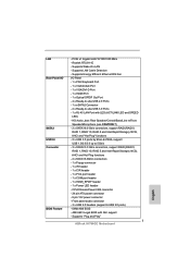
... pin ATX power connector - 8 pin 12V power connector - Supports "Plug and Play" 7 ASRock H67M-GE Motherboard English Realtek RTL8111E - PCIE x1 Gigabit LAN 10/100/1000 Mb/s - Front panel audio connector - 3 x USB 2.0 headers (support 6 USB 2.0 ports) - 64Mb AMI BIOS - AMI UEFI Legal BIOS with LED (ACT/LINK LED and SPEED LED) - Supports LAN Cable...
... pin ATX power connector - 8 pin 12V power connector - Supports "Plug and Play" 7 ASRock H67M-GE Motherboard English Realtek RTL8111E - PCIE x1 Gigabit LAN 10/100/1000 Mb/s - Front panel audio connector - 3 x USB 2.0 headers (support 6 USB 2.0 ports) - 64Mb AMI BIOS - AMI UEFI Legal BIOS with LED (ACT/LINK LED and SPEED LED) - Supports LAN Cable...

Quick Installation Guide
Page 169
CPU 24 핀 ATX 8 핀 ATX 12V USB 2.0 헤더 3 개 (6 USB 2.0 2개 ) - 64Mb AMI BIOS - GUI AMI UEFI 적합형 BIOS ACPI 1.1 SMBIOS 2.3.1 지원 169 ASRock H67M-GE Motherboard 한 국 어 후면판 I/O SATA3 USB 3.0 BIOS I/O Panel - 1 개 PS/2 1 개의 VGA/D-Sub 포트 - 1 개의 VGA/DVI-D 포...
CPU 24 핀 ATX 8 핀 ATX 12V USB 2.0 헤더 3 개 (6 USB 2.0 2개 ) - 64Mb AMI BIOS - GUI AMI UEFI 적합형 BIOS ACPI 1.1 SMBIOS 2.3.1 지원 169 ASRock H67M-GE Motherboard 한 국 어 후면판 I/O SATA3 USB 3.0 BIOS I/O Panel - 1 개 PS/2 1 개의 VGA/D-Sub 포트 - 1 개의 VGA/DVI-D 포...

Quick Installation Guide
Page 253
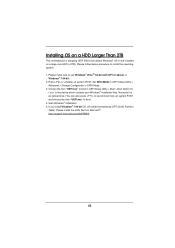
...64257;les. If you install Windows® 7 64-bit OS, OS will be installed on a large size HDD (>2TB). Choose the item "UEFI:xxx" to boot in UEFI Setup Utility > Advanced > Storage Configuration > SATA Mode. 3. Normally it is an optical drive.) You can also press to launch boot... make sure to install the operating system. 1. Start Windows® installation. 5. Installing OS on a HDD Larger Than 2TB This motherboard is adopting UEFI BIOS that allows Windows® OS to be formatted by GPT (GUID Partition Table). Please follow below procedure to use Windows® VistaTM 64-bit...
...64257;les. If you install Windows® 7 64-bit OS, OS will be installed on a large size HDD (>2TB). Choose the item "UEFI:xxx" to boot in UEFI Setup Utility > Advanced > Storage Configuration > SATA Mode. 3. Normally it is an optical drive.) You can also press to launch boot... make sure to install the operating system. 1. Start Windows® installation. 5. Installing OS on a HDD Larger Than 2TB This motherboard is adopting UEFI BIOS that allows Windows® OS to be formatted by GPT (GUID Partition Table). Please follow below procedure to use Windows® VistaTM 64-bit...

