
User Manual
Page 3
Contents 1 Introduction 5 1.1 Package Contents 5 1.2 Speci cations 6 1.3 Motherboard Layout 12 1.4 I/O Panel 13 2 Installation 15 2.1 Screw Holes 15 2.2 Pre-installation Precautions 15 2.3 CPU Installation 16 2.4 Installation of Heatsink and CPU fan 18 2.5 Installation of Memory Modules (DIMM 19 2.6 Expansion Slots (PCI and PCI Express Slots 21 2.7 Dual Monitor and Surround Display Features 22 2.9 Jumpers Setup...
Contents 1 Introduction 5 1.1 Package Contents 5 1.2 Speci cations 6 1.3 Motherboard Layout 12 1.4 I/O Panel 13 2 Installation 15 2.1 Screw Holes 15 2.2 Pre-installation Precautions 15 2.3 CPU Installation 16 2.4 Installation of Heatsink and CPU fan 18 2.5 Installation of Memory Modules (DIMM 19 2.6 Expansion Slots (PCI and PCI Express Slots 21 2.7 Dual Monitor and Surround Display Features 22 2.9 Jumpers Setup...

User Manual
Page 4
3 UEFI SETUP UTILITY 41 3.1 Introduction 41 3.1.1 UEFI Menu Bar 41 3.1.2 Navigation Keys 42 3.2 Main Screen 42 3.3 Advanced Screen 43 3.3.1 CPU Con guration 44 3.3.2 Intel IGD SWSCI OpRegion Con guration........... 46 3.3.3 Integrated Clock Chip Con guration 47 3.3.4 DRAM Con guration 48 3.3.5 North Bridge Con guration 50 3.3.6 ...
3 UEFI SETUP UTILITY 41 3.1 Introduction 41 3.1.1 UEFI Menu Bar 41 3.1.2 Navigation Keys 42 3.2 Main Screen 42 3.3 Advanced Screen 43 3.3.1 CPU Con guration 44 3.3.2 Intel IGD SWSCI OpRegion Con guration........... 46 3.3.3 Integrated Clock Chip Con guration 47 3.3.4 DRAM Con guration 48 3.3.5 North Bridge Con guration 50 3.3.6 ...

User Manual
Page 5
...ASRock H67M-GE Quick Installation Guide ASRock H67M-GE Support CD 2 x Serial ATA (SATA) Data Cables (Optional) 1 x I/O Panel Shield 1 x 3D Red/Cyan Anaglyph Glasses (Optional) ASRock Reminds You... Chapter 3 and 4 contain the con guration guide to quality and endurance. You may nd the latest VGA cards and CPU support lists on ASRock website without notice. ASRock website http://www.asrock... to the "User Manual" in our support CD for purchasing ASRock H67M-GE motherboard, a reliable motherboard produced under ASRock's consistently stringent quality control. In case any modi cations of ...
...ASRock H67M-GE Quick Installation Guide ASRock H67M-GE Support CD 2 x Serial ATA (SATA) Data Cables (Optional) 1 x I/O Panel Shield 1 x 3D Red/Cyan Anaglyph Glasses (Optional) ASRock Reminds You... Chapter 3 and 4 contain the con guration guide to quality and endurance. You may nd the latest VGA cards and CPU support lists on ASRock website without notice. ASRock website http://www.asrock... to the "User Manual" in our support CD for purchasing ASRock H67M-GE motherboard, a reliable motherboard produced under ASRock's consistently stringent quality control. In case any modi cations of ...
User Manual
Page 6
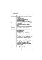
...Audio with max. Premium Blu-ray audio support 6 Supports HDMI 1.4a Technology with Content Protection (Realtek ALC892 Audio Codec) - 1.2 Specifications Platform CPU Chipset Memory Expansion Slot Graphics * Audio - shared memory 1759MB (see CAUTION 3) - 1 x PCI Express 2.0 x16 slot (blue @ x16 ... Factor: 9.6-in x 9.6-in LGA1155 Package - 4 + 1 Power Phase Design - Intel® HD Graphics 2000/3000 - Supports K-Series unlocked CPU - Dual Channel DDR3 Memory Technology (see CAUTION 5) - resolution up to 2048x1536 @ 75Hz - resolution up to 1920x1200 @ 60Hz - Max. Pixel...
...Audio with max. Premium Blu-ray audio support 6 Supports HDMI 1.4a Technology with Content Protection (Realtek ALC892 Audio Codec) - 1.2 Specifications Platform CPU Chipset Memory Expansion Slot Graphics * Audio - shared memory 1759MB (see CAUTION 3) - 1 x PCI Express 2.0 x16 slot (blue @ x16 ... Factor: 9.6-in x 9.6-in LGA1155 Package - 4 + 1 Power Phase Design - Intel® HD Graphics 2000/3000 - Supports K-Series unlocked CPU - Dual Channel DDR3 Memory Technology (see CAUTION 5) - resolution up to 2048x1536 @ 75Hz - resolution up to 1920x1200 @ 60Hz - Max. Pixel...

User Manual
Page 7
CPU/Chassis/Power FAN connector - 24 pin ATX power connector - 8 pin 12V power connector - AMI UEFI Legal BIOS with LED (ACT/LINK LED and SPEED LED) - ...
CPU/Chassis/Power FAN connector - 24 pin ATX power connector - 8 pin 12V power connector - AMI UEFI Legal BIOS with LED (ACT/LINK LED and SPEED LED) - ...
User Manual
Page 8
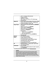
... Up Events - SMBIOS 2.3.1 Support - Drivers, Utilities, AntiVirus Software (Trial Version), ASRock Software Suite (CyberLink DVD Suite - ASRock Extreme Tuning Utility (AXTU) (see CAUTION 13) - ASRock APP Charger (see CAUTION 14) - Combo Cooler Option (C.C.O.) (see CAUTION 11) - CPU Temperature Sensing Monitor - CPU/Chassis/Power Fan Tachometer - CPU/Chassis Quiet Fan (Allow Chassis Fan Speed Auto-Adjust by...
... Up Events - SMBIOS 2.3.1 Support - Drivers, Utilities, AntiVirus Software (Trial Version), ASRock Software Suite (CyberLink DVD Suite - ASRock Extreme Tuning Utility (AXTU) (see CAUTION 13) - ASRock APP Charger (see CAUTION 14) - Combo Cooler Option (C.C.O.) (see CAUTION 11) - CPU Temperature Sensing Monitor - CPU/Chassis/Power Fan Tachometer - CPU/Chassis Quiet Fan (Allow Chassis Fan Speed Auto-Adjust by...
User Manual
Page 9
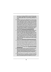
...the operating system limitation, the actual memory size may be less than 4GB for the reservation for you to improve efficiency when the CPU cores are idle without entering operating systems rst like MS-DOS or Windows®. In OC DNA, you implement Dual Channel Memory... functions in -one tool to read the installation guide of "Hyper Threading Technology", please check page 44. 2. Before you can choose to access ASRock Instant Flash. ASRock Extreme Tuning Utility (AXTU) is an all-in a user-friendly interface, which is supported under Windows® 7 64-bit / 7. CAUTION!...
...the operating system limitation, the actual memory size may be less than 4GB for the reservation for you to improve efficiency when the CPU cores are idle without entering operating systems rst like MS-DOS or Windows®. In OC DNA, you implement Dual Channel Memory... functions in -one tool to read the installation guide of "Hyper Threading Technology", please check page 44. 2. Before you can choose to access ASRock Instant Flash. ASRock Extreme Tuning Utility (AXTU) is an all-in a user-friendly interface, which is supported under Windows® 7 64-bit / 7. CAUTION!...
User Manual
Page 10
...easily enjoy the marvelous charging experience than before. drive, then you resume the system, please check if the CPU fan on -the-go. ASRock website: http://www.asrock.com/Feature/AppCharger/index.asp 12. Before you can be noticed that the USB ash drive or hard drive... all the 775 and 1156 CPU Fan can update your iPhone/iPod touch as iPhone/iPod/iPad Touch, ASRock has prepared a wonderful solution for a more personal Internet experience. ASRock website: http://www.asrock.com/Feature/Aiwi/index.asp 11. ASRock APP Charger. ASRock motherboards are exclusively equipped with ...
...easily enjoy the marvelous charging experience than before. drive, then you resume the system, please check if the CPU fan on -the-go. ASRock website: http://www.asrock.com/Feature/AppCharger/index.asp 12. Before you can be noticed that the USB ash drive or hard drive... all the 775 and 1156 CPU Fan can update your iPhone/iPod touch as iPhone/iPod/iPad Touch, ASRock has prepared a wonderful solution for a more personal Internet experience. ASRock website: http://www.asrock.com/Feature/Aiwi/index.asp 11. ASRock APP Charger. ASRock motherboards are exclusively equipped with ...
User Manual
Page 12
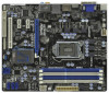
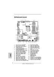
...34 Dual Channel USB 3.0 T: USB4 Top: B: USB5 RJ-45 CHA_FAN1 CHA_FAN2 LAN PHY 8 Top: CTR BASS Center: REAR SPK Bottom: Optical SPDIF SATA3_1 SATA3_0 CMOS H67M-GE Battery 9 Top: LINE IN Center: FRONT Bottom: MIC IN USB 3.0 33 PCIE1 10 32 DX10.1 PCI Express 2.0 ErP/EuP Ready Super I/O PCIE2 31 PCIE3 Intel... RESET 15 16 28 27 26 25 24 23 22 21 20 19 18 17 1 Power Fan Connector (PWR_FAN1) 19 Power LED Header (PLED1) 2 CPU Fan Connector (CPU_FAN1) 20 USB 2.0 Header (USB8_9, Blue) 3 ATX 12V Power Connector (ATX12V1) 21 USB 2.0 Header (USB10_11, Blue) 4 1155-Pin...
...34 Dual Channel USB 3.0 T: USB4 Top: B: USB5 RJ-45 CHA_FAN1 CHA_FAN2 LAN PHY 8 Top: CTR BASS Center: REAR SPK Bottom: Optical SPDIF SATA3_1 SATA3_0 CMOS H67M-GE Battery 9 Top: LINE IN Center: FRONT Bottom: MIC IN USB 3.0 33 PCIE1 10 32 DX10.1 PCI Express 2.0 ErP/EuP Ready Super I/O PCIE2 31 PCIE3 Intel... RESET 15 16 28 27 26 25 24 23 22 21 20 19 18 17 1 Power Fan Connector (PWR_FAN1) 19 Power LED Header (PLED1) 2 CPU Fan Connector (CPU_FAN1) 20 USB 2.0 Header (USB8_9, Blue) 3 ATX 12V Power Connector (ATX12V1) 21 USB 2.0 Header (USB10_11, Blue) 4 1155-Pin...

User Manual
Page 16
...cap. 2. It is recommended to use the cap tab to fully open position at approximately 135 degrees. Step 1-2. Step 1-3. Otherwise, the CPU will be placed if returning the motherboard for after service. 16 This cap must be seriously damaged. Do not force to clear retention tab.... Disengaging the lever by depressing down and out on the socket. Remove PnP Cap (Pick and Place Cap). 1. 2.3 CPU Installation For the installation of Intel 1155-Pin CPU, please follow the steps below. Rotate the load plate to fully open position at approximately 100 degrees. Load Plate Load ...
...cap. 2. It is recommended to use the cap tab to fully open position at approximately 135 degrees. Step 1-2. Step 1-3. Otherwise, the CPU will be placed if returning the motherboard for after service. 16 This cap must be seriously damaged. Do not force to clear retention tab.... Disengaging the lever by depressing down and out on the socket. Remove PnP Cap (Pick and Place Cap). 1. 2.3 CPU Installation For the installation of Intel 1155-Pin CPU, please follow the steps below. Rotate the load plate to fully open position at approximately 100 degrees. Load Plate Load ...

User Manual
Page 17
... load plate onto the IHS. Step 4-2. Step 3. black line Step 3-2. Step 3-3. Verify that the CPU is marked with IHS (Integrated Heat Sink) up. Orient the CPU with black line. Carefully place the CPU into the socket by the edge where is within the socket and properly mated to match the... two orientation key notches of the CPU with the two alignment keys of the socket. Insert the 1155-Pin CPU: Step 3-1. Step 4. orientation key notch alignment key Pin1 Pin1 orientation key notch 1155-Pin CPU alignment key 1155-Pin Socket For proper inserting, please ensure...
... load plate onto the IHS. Step 4-2. Step 3. black line Step 3-2. Step 3-3. Verify that the CPU is marked with IHS (Integrated Heat Sink) up. Orient the CPU with black line. Carefully place the CPU into the socket by the edge where is within the socket and properly mated to match the... two orientation key notches of the CPU with the two alignment keys of the socket. Insert the 1155-Pin CPU: Step 3-1. Step 4. orientation key notch alignment key Pin1 Pin1 orientation key notch 1155-Pin CPU alignment key 1155-Pin Socket For proper inserting, please ensure...

User Manual
Page 18
... fastener clockwise, then press down the fasteners without rotating them clockwise, the heatsink cannot be noticed that supports Intel 1155-Pin CPU. Then connect the CPU fan to ensure cable does not interfere with tie-wrap to the CPU_FAN connector (CPU_FAN1, see page 12, No. 2). ...slots pointing straight out Press Down (4 Places) If you need to spray thermal interface material between the CPU and the heatsink to the instruction manuals of your CPU fan and heatsink. Below is equipped with the motherboard throughholes. Apply Thermal Interface Material Step 2. Fan ...
... fastener clockwise, then press down the fasteners without rotating them clockwise, the heatsink cannot be noticed that supports Intel 1155-Pin CPU. Then connect the CPU fan to ensure cable does not interfere with tie-wrap to the CPU_FAN connector (CPU_FAN1, see page 12, No. 2). ...slots pointing straight out Press Down (4 Places) If you need to spray thermal interface material between the CPU and the heatsink to the instruction manuals of your CPU fan and heatsink. Below is equipped with the motherboard throughholes. Apply Thermal Interface Material Step 2. Fan ...

User Manual
Page 29
... connector on when the system is reading or writing data. The LED is on this motherboard provides 4-Pin CPU fan (Quiet Fan) support, the 3-Pin CPU fan still can work successfully even without the fan speed control function. Power LED Header (3-pin PLED1) (see p.12 No. 19) 1 PLEDPLED+ ...match the black wire to the hard drive activity LED on when the hard drive is operating. CPU Fan Connectors (4-pin CPU_FAN1) (see p.12 No. 2) FAN_SPEED_CONTROL CPU_FAN_SPEED +12V GND 1 2 3 4 Please connect the CPU fan cable to the connector and match the black wire to this header, make sure the ...
... connector on when the system is reading or writing data. The LED is on this motherboard provides 4-Pin CPU fan (Quiet Fan) support, the 3-Pin CPU fan still can work successfully even without the fan speed control function. Power LED Header (3-pin PLED1) (see p.12 No. 19) 1 PLEDPLED+ ...match the black wire to the hard drive activity LED on when the hard drive is operating. CPU Fan Connectors (4-pin CPU_FAN1) (see p.12 No. 2) FAN_SPEED_CONTROL CPU_FAN_SPEED +12V GND 1 2 3 4 Please connect the CPU fan cable to the connector and match the black wire to this header, make sure the ...

User Manual
Page 43
ASRock Instant Flash ASRock Instant Flash is a UEFI flash utility embedded in this section may set the con gurations for the following items: CPU Con guration, Intel IGD SWSCI OpRegion Con guration, Integrated Clock Chip Con guration, DRAM Con guration, North Bridge Con guration, South Bridge Con ...UEFI only in a few clicks without entering operating systems rst like MS-DOS or Windows®. This convenient UEFI update tool allows you execute ASRock Instant Flash utility, the utility will show the UEFI les and their respective information. Please be noted that the USB ash drive or hard...
ASRock Instant Flash ASRock Instant Flash is a UEFI flash utility embedded in this section may set the con gurations for the following items: CPU Con guration, Intel IGD SWSCI OpRegion Con guration, Integrated Clock Chip Con guration, DRAM Con guration, North Bridge Con guration, South Bridge Con ...UEFI only in a few clicks without entering operating systems rst like MS-DOS or Windows®. This convenient UEFI update tool allows you execute ASRock Instant Flash utility, the utility will show the UEFI les and their respective information. Please be noted that the USB ash drive or hard...

User Manual
Page 44
... this item to enable or disable Intel Turbo Boost Technology. The default value is [Enabled]. This item will be hidden if the current CPU does not support Intel SpeedStep technology. The default value is [Enabled]. Intel Hyper Threading Technology To enable this feature, it requires a computer...that enabling this motherboard. Intel Turbo Boost Technology Use this item to change the ratio value of this function may reduce CPU voltage and lead to add voltage when CPU is Intel's new power saving technology. Con guration options: [Auto] and [Manual]. Core Current Limit Use this ...
... this item to enable or disable Intel Turbo Boost Technology. The default value is [Enabled]. This item will be hidden if the current CPU does not support Intel SpeedStep technology. The default value is [Enabled]. Intel Hyper Threading Technology To enable this feature, it requires a computer...that enabling this motherboard. Intel Turbo Boost Technology Use this item to change the ratio value of this function may reduce CPU voltage and lead to add voltage when CPU is Intel's new power saving technology. Con guration options: [Auto] and [Manual]. Core Current Limit Use this ...

User Manual
Page 45
...processor package. No-Excute Memory Protection No-Execution (NX) Memory Protection Technology is [All]. This option will be hidden if the current CPU does not support No-Excute Memory Protection. Enhance Halt State (C1E) All processors support the Halt State (C1). Package C State Support... Selected option will be hidden if the installed CPU does not support Intel Virtualization Technology. The default value is supported through the native processor instructions HLT and MWAIT and requires no hardware...
...processor package. No-Excute Memory Protection No-Execution (NX) Memory Protection Technology is [All]. This option will be hidden if the current CPU does not support No-Excute Memory Protection. Enhance Halt State (C1E) All processors support the Halt State (C1). Package C State Support... Selected option will be hidden if the installed CPU does not support Intel Virtualization Technology. The default value is supported through the native processor instructions HLT and MWAIT and requires no hardware...

User Manual
Page 54
... Voltage Use this to select VTT Voltage. VTT Voltage Use this to select CPU PLL Voltage. Con guration options: [Auto], [0.815V] to select CPU Core Voltage Offset. The default value is [Auto]. 3.3.9 Voltage Configuration CPU Core Voltage Offset Use this to [1.634V]. PCH Voltage Use this to [2.310V]. Con guration options: [Auto], [1.548V...
... Voltage Use this to select VTT Voltage. VTT Voltage Use this to select CPU PLL Voltage. Con guration options: [Auto], [0.815V] to select CPU Core Voltage Offset. The default value is [Auto]. 3.3.9 Voltage Configuration CPU Core Voltage Offset Use this to [1.634V]. PCH Voltage Use this to [2.310V]. Con guration options: [Auto], [1.548V...

User Manual
Page 57
...Con guration options: [Full On] and [Automatic Mode]. Con guration options: [Full On] and [Automatic Mode]. The default is value [Full On]. CPU Fan Setting This allows you to set the power fan speed. Chassis Fan 1 Setting This allows you to set the chassis fan 2 speed. Over ... [Full On]. Power Fan Setting This allows you to monitor the status of the hardware on your system, including the parameters of the CPU temperature, motherboard temperature, CPU fan speed, chassis fan speed, and the critical voltage. The default is value [Full On]. The default is value [Full On]. ...
...Con guration options: [Full On] and [Automatic Mode]. Con guration options: [Full On] and [Automatic Mode]. The default is value [Full On]. CPU Fan Setting This allows you to set the power fan speed. Chassis Fan 1 Setting This allows you to set the chassis fan 2 speed. Over ... [Full On]. Power Fan Setting This allows you to monitor the status of the hardware on your system, including the parameters of the CPU temperature, motherboard temperature, CPU fan speed, chassis fan speed, and the critical voltage. The default is value [Full On]. The default is value [Full On]. ...
Quick Installation Guide
Page 2
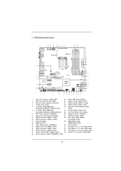
... 22 21 20 19 18 17 1 Power Fan Connector (PWR_FAN1) 19 Power LED Header (PLED1) 2 CPU Fan Connector (CPU_FAN1) 20 USB 2.0 Header (USB8_9, Blue) 3 ATX 12V Power Connector (ATX12V1) 21 USB 2.0 Header (USB10_11,... Blue) 4 1155-Pin CPU Socket 22 USB 2.0 Header (USB6_7, Blue) 5 2 x 240-pin DDR3 DIMM Slots 23 Consumer Infrared Module Header (Dual Channel: DDR3_A1... (PANEL1, White) 34 Chassis Fan Connector (CHA_FAN2) 18 Chassis Speaker Header (SPEAKER 1, White) 2 ASRock H67M-GE Motherboard English
... 22 21 20 19 18 17 1 Power Fan Connector (PWR_FAN1) 19 Power LED Header (PLED1) 2 CPU Fan Connector (CPU_FAN1) 20 USB 2.0 Header (USB8_9, Blue) 3 ATX 12V Power Connector (ATX12V1) 21 USB 2.0 Header (USB10_11,... Blue) 4 1155-Pin CPU Socket 22 USB 2.0 Header (USB6_7, Blue) 5 2 x 240-pin DDR3 DIMM Slots 23 Consumer Infrared Module Header (Dual Channel: DDR3_A1... (PANEL1, White) 34 Chassis Fan Connector (CHA_FAN2) 18 Chassis Speaker Header (SPEAKER 1, White) 2 ASRock H67M-GE Motherboard English

Quick Installation Guide
Page 5
... support CD for purchasing ASRock H67M-GE motherboard, a reliable motherboard produced under ASRock's consistently stringent quality control. More detailed information of the motherboard and step-bystep installation guide. For the BIOS setup, please refer to change without further notice. 1. You may find the latest VGA cards and CPU support lists on ASRock website without notice...
... support CD for purchasing ASRock H67M-GE motherboard, a reliable motherboard produced under ASRock's consistently stringent quality control. More detailed information of the motherboard and step-bystep installation guide. For the BIOS setup, please refer to change without further notice. 1. You may find the latest VGA cards and CPU support lists on ASRock website without notice...


