User Manual
Page 11
...power supply manufacturer for Energy Using Product, was a provision regulated by European Union to adopt three different CPU cooler types, Socket LGA 775, LGA 1155 and LGA 1156. Combo Cooler Option (C.C.O.) provides the exible option to de ne the power consumption for the completed system. EuP, stands for more... details. 11 According to Intel's suggestion, the EuP ready power supply must meet EuP standard, an EuP ready motherboard and an EuP ready power supply are required. 16. Please be noticed that not all the 775 and 1156 CPU Fan can be under 100...
...power supply manufacturer for Energy Using Product, was a provision regulated by European Union to adopt three different CPU cooler types, Socket LGA 775, LGA 1155 and LGA 1156. Combo Cooler Option (C.C.O.) provides the exible option to de ne the power consumption for the completed system. EuP, stands for more... details. 11 According to Intel's suggestion, the EuP ready power supply must meet EuP standard, an EuP ready motherboard and an EuP ready power supply are required. 16. Please be noticed that not all the 775 and 1156 CPU Fan can be under 100...
User Manual
Page 12
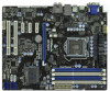
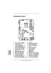
1.3 Motherboard Layout PS2 Keyboard USB 2.0 T: USB0 B: USB1 1 2 3 21.1cm (8.3 in) 4 5 PWR_FAN1 ATX12V1 ...: LINE IN Center: FRONT Bottom: MIC IN Designed in Taipei CHA_FAN1 CPU_FAN2 CPU_FAN1 34 CHA_FAN3 CHA_FAN2 33 LAN PHY H67DE3 7 8 32 PCIE1 PCI Express 2.0 CMOS ErP/EuP Ready 31 PCIE2 Battery USB 3.0 30 Super I/O PCIE3 Intel...15 1 Power Fan Connector (PWR_FAN1) 19 64Mb SPI Flash 2 ATX 12V Power Connector (ATX12V1) 20 Clear CMOS Jumper (CLRCMOS1) 3 1155-Pin CPU Socket 21 USB 2.0 Header (USB8_9, Blue) 4 2 x 240-pin DDR3 DIMM Slots 22 USB 2.0 Header (USB6_7,...
1.3 Motherboard Layout PS2 Keyboard USB 2.0 T: USB0 B: USB1 1 2 3 21.1cm (8.3 in) 4 5 PWR_FAN1 ATX12V1 ...: LINE IN Center: FRONT Bottom: MIC IN Designed in Taipei CHA_FAN1 CPU_FAN2 CPU_FAN1 34 CHA_FAN3 CHA_FAN2 33 LAN PHY H67DE3 7 8 32 PCIE1 PCI Express 2.0 CMOS ErP/EuP Ready 31 PCIE2 Battery USB 3.0 30 Super I/O PCIE3 Intel...15 1 Power Fan Connector (PWR_FAN1) 19 64Mb SPI Flash 2 ATX 12V Power Connector (ATX12V1) 20 Clear CMOS Jumper (CLRCMOS1) 3 1155-Pin CPU Socket 21 USB 2.0 Header (USB8_9, Blue) 4 2 x 240-pin DDR3 DIMM Slots 22 USB 2.0 Header (USB6_7,...
User Manual
Page 16
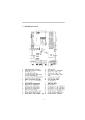
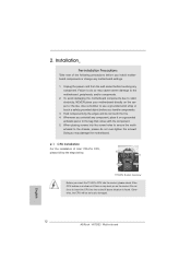
... to clear retention tab. This cap must be seriously damaged. 2.3 CPU Installation For the installation of Intel 1155-Pin CPU, please follow the steps below. Otherwise, the CPU will be placed if returning the motherboard for after service. 16 Step 1-2. Disengaging the lever by depressing down and out on the socket. It...
... to clear retention tab. This cap must be seriously damaged. 2.3 CPU Installation For the installation of Intel 1155-Pin CPU, please follow the steps below. Otherwise, the CPU will be placed if returning the motherboard for after service. 16 Step 1-2. Disengaging the lever by depressing down and out on the socket. It...
User Manual
Page 18
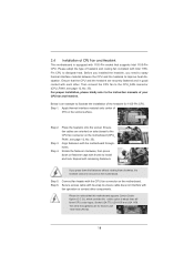
Ensure that this motherboard supports Combo Cooler Option (C.C.O.), which provides the exible option to adopt three different CPU cooler types, Socket LGA 775, LGA 1155 and LGA 1156. Step 1. Step 6. Connect fan header with thumb to install and lock. The white throughholes are for 1155-Pin CPU. Ensure fan cables are securely fastened and...
Ensure that this motherboard supports Combo Cooler Option (C.C.O.), which provides the exible option to adopt three different CPU cooler types, Socket LGA 775, LGA 1155 and LGA 1156. Step 1. Step 6. Connect fan header with thumb to install and lock. The white throughholes are for 1155-Pin CPU. Ensure fan cables are securely fastened and...
Quick Installation Guide
Page 2
...: LINE IN Center: FRONT Bottom: MIC IN Designed in Taipei CHA_FAN1 CPU_FAN2 CPU_FAN1 34 CHA_FAN3 CHA_FAN2 33 LAN PHY H67DE3 7 8 32 PCIE1 PCI Express 2.0 CMOS ErP/EuP Ready 31 PCIE2 Battery USB 3.0 30 Super I/O PCIE3 Intel...15 1 Power Fan Connector (PWR_FAN1) 19 64Mb SPI Flash 2 ATX 12V Power Connector (ATX12V1) 20 Clear CMOS Jumper (CLRCMOS1) 3 1155-Pin CPU Socket 21 USB 2.0 Header (USB8_9, Blue) 4 2 x 240-pin DDR3 DIMM Slots 22 USB 2.0 Header (USB6_7,... 18 Chassis Speaker Header (SPEAKER 1, White) 35 CPU Fan Connector (CPU_FAN1) 2 ASRock H67DE3 Motherboard English
...: LINE IN Center: FRONT Bottom: MIC IN Designed in Taipei CHA_FAN1 CPU_FAN2 CPU_FAN1 34 CHA_FAN3 CHA_FAN2 33 LAN PHY H67DE3 7 8 32 PCIE1 PCI Express 2.0 CMOS ErP/EuP Ready 31 PCIE2 Battery USB 3.0 30 Super I/O PCIE3 Intel...15 1 Power Fan Connector (PWR_FAN1) 19 64Mb SPI Flash 2 ATX 12V Power Connector (ATX12V1) 20 Clear CMOS Jumper (CLRCMOS1) 3 1155-Pin CPU Socket 21 USB 2.0 Header (USB8_9, Blue) 4 2 x 240-pin DDR3 DIMM Slots 22 USB 2.0 Header (USB6_7,... 18 Chassis Speaker Header (SPEAKER 1, White) 35 CPU Fan Connector (CPU_FAN1) 2 ASRock H67DE3 Motherboard English

Quick Installation Guide
Page 11
... recommend you checking with the power supply manufacturer for the completed system. According to de ne the power consumption for more details. 11 ASRock H67DE3 Motherboard English To meet the standard of the completed system shall be used. 17. Please be noticed that not all the 775 and 1156 CPU... Fan can be under 100 mA current consumption. 16. According to adopt three different CPU cooler types, Socket LGA 775, LGA 1155 and LGA 1156. Combo Cooler Option (C.C.O.) provides the exible option to Intel's suggestion, the EuP ready power supply must meet EuP standard, ...
... recommend you checking with the power supply manufacturer for the completed system. According to de ne the power consumption for more details. 11 ASRock H67DE3 Motherboard English To meet the standard of the completed system shall be used. 17. Please be noticed that not all the 775 and 1156 CPU... Fan can be under 100 mA current consumption. 16. According to adopt three different CPU cooler types, Socket LGA 775, LGA 1155 and LGA 1156. Combo Cooler Option (C.C.O.) provides the exible option to Intel's suggestion, the EuP ready power supply must meet EuP standard, ...
Quick Installation Guide
Page 12
... or the like. Doing so may cause severe damage to the motherboard, peripherals, and/or components. 2. Load Plate Contact Array Load Lever Socket Body 1155-Pin Socket Overview Before you install motherboard components or change any bent pin on the socket. English 12 ASRock H67DE3 Motherboard Whenever you handle components. 3. When placing screws into the socket...
... or the like. Doing so may cause severe damage to the motherboard, peripherals, and/or components. 2. Load Plate Contact Array Load Lever Socket Body 1155-Pin Socket Overview Before you install motherboard components or change any bent pin on the socket. English 12 ASRock H67DE3 Motherboard Whenever you handle components. 3. When placing screws into the socket...
Quick Installation Guide
Page 13
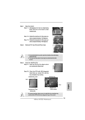
...cap tab to match the two orientation key notches of the CPU with the two alignment keys of the socket. 13 ASRock H67DE3 Motherboard English Step 1-2. Step 1-3. Insert the 1155-Pin CPU: Step 3-1. Locate Pin1 and the two orientation key notches. Step 2. This cap must be placed if... returning the motherboard for after service. Step 1. Rotate the load plate to fully open position at approximately 100 degrees. Remove PnP Cap (Pick and Place Cap). 1. orientation key notch alignment key Pin1 Pin1 orientation key notch 1155-Pin CPU alignment key 1155-Pin Socket For ...
...cap tab to match the two orientation key notches of the CPU with the two alignment keys of the socket. 13 ASRock H67DE3 Motherboard English Step 1-2. Step 1-3. Insert the 1155-Pin CPU: Step 3-1. Locate Pin1 and the two orientation key notches. Step 2. This cap must be placed if... returning the motherboard for after service. Step 1. Rotate the load plate to fully open position at approximately 100 degrees. Remove PnP Cap (Pick and Place Cap). 1. orientation key notch alignment key Pin1 Pin1 orientation key notch 1155-Pin CPU alignment key 1155-Pin Socket For ...

Quick Installation Guide
Page 14
... you press down lightly on the motherboard. Step 4. Step 3. Repeat with the motherboard throughholes. Please be secured on load plate, engage the load lever. 2.2 Installation of the heatsink for Socket LGA 1155/1156 CPU fan. 14 ASRock H67DE3 Motherboard English Apply thermal interface material onto ...center of your CPU fan and heatsink. Secure excess cable with tie-wrap to the instruction manuals of IHS on the motherboard. Connect fan header with...
... you press down lightly on the motherboard. Step 4. Step 3. Repeat with the motherboard throughholes. Please be secured on load plate, engage the load lever. 2.2 Installation of the heatsink for Socket LGA 1155/1156 CPU fan. 14 ASRock H67DE3 Motherboard English Apply thermal interface material onto ...center of your CPU fan and heatsink. Secure excess cable with tie-wrap to the instruction manuals of IHS on the motherboard. Connect fan header with...

Quick Installation Guide
Page 172
... EuP 5V 100 mA 50 ASRock H67DE3 Motherboard asrock.com/Feature/AppCharger/index.asp 12 SmartView IE ASRock SmartView SmartView OS 버전이 Windows® 7 / 7 64 비트 / VistaTM / VistaTM 64 IE8 ASRock http://www.asrock.com/ Feature/SmartView/index.asp 13 CPU PC CPU 14 C.C.O.) 은 3 CPU LGA 775, LGA 1155 와 LGA 1156 775 와...
... EuP 5V 100 mA 50 ASRock H67DE3 Motherboard asrock.com/Feature/AppCharger/index.asp 12 SmartView IE ASRock SmartView SmartView OS 버전이 Windows® 7 / 7 64 비트 / VistaTM / VistaTM 64 IE8 ASRock http://www.asrock.com/ Feature/SmartView/index.asp 13 CPU PC CPU 14 C.C.O.) 은 3 CPU LGA 775, LGA 1155 와 LGA 1156 775 와...
Quick Installation Guide
Page 173
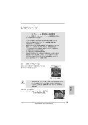
EuP 2 1 2 3 IC 4 5 2.1 CPU 설치 Intel 1155 핀 CPU 장착판 Load Plate Load Lever Contact Array Socket Body 1155 1155 핀 CPU CPU CPU CPU 한국어 173 ASRock H67DE3 Motherboard
EuP 2 1 2 3 IC 4 5 2.1 CPU 설치 Intel 1155 핀 CPU 장착판 Load Plate Load Lever Contact Array Socket Body 1155 1155 핀 CPU CPU CPU CPU 한국어 173 ASRock H67DE3 Motherboard

Quick Installation Guide
Page 174
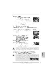
IHS 1 니다 . 정렬 키 Pin1 174 Pin1 1155 핀 CPU 정렬 키 1155 핀 소켓 CPU 3-3 단계 . 3-4 단계 . CPU CPU ASRock H67DE3 Motherboard 1 1-1 1-2 단계 . 1-3 단계 . 135 100 2 단계 . PnP 흑색 선 한 국 어 1 PnP 2 오. 3 단계 . 1156 핀 CPU 3-1 CPU 3-2 단계 .
IHS 1 니다 . 정렬 키 Pin1 174 Pin1 1155 핀 CPU 정렬 키 1155 핀 소켓 CPU 3-3 단계 . 3-4 단계 . CPU CPU ASRock H67DE3 Motherboard 1 1-1 1-2 단계 . 1-3 단계 . 135 100 2 단계 . PnP 흑색 선 한 국 어 1 PnP 2 오. 3 단계 . 1156 핀 CPU 3-1 CPU 3-2 단계 .

Quick Installation Guide
Page 175
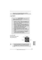
4 4-1 IHS 4-2 4-3 2.2 CPU CPU 1155 1 IHS Apply Thermal Interface Material 2 CPU CPU_FAN1, 2 35 Fan cables on side closest to MB header 3 Fastener slots pointing straight out 4 Press Down (4 Places) 4 곳 ).) 5 CPU 6 3 CPU LGA 775, LGA 1155 와 LGA 1156 C.C.O LGA 1155/1156 CPU 한국어 175 ASRock H67DE3 Motherboard
4 4-1 IHS 4-2 4-3 2.2 CPU CPU 1155 1 IHS Apply Thermal Interface Material 2 CPU CPU_FAN1, 2 35 Fan cables on side closest to MB header 3 Fastener slots pointing straight out 4 Press Down (4 Places) 4 곳 ).) 5 CPU 6 3 CPU LGA 775, LGA 1155 와 LGA 1156 C.C.O LGA 1155/1156 CPU 한국어 175 ASRock H67DE3 Motherboard
Quick Installation Guide
Page 195
IC 4. 2.1 CPU Intel 1155-LAND CPU Load Plate Load Lever Contact Array Socket Body 1155 1155-LAND CPU CPU CPU CPU 1 1-1 日本語 195 ASRock H67DE3 Motherboard 1. 2. 3.
IC 4. 2.1 CPU Intel 1155-LAND CPU Load Plate Load Lever Contact Array Socket Body 1155 1155-LAND CPU CPU CPU CPU 1 1-1 日本語 195 ASRock H67DE3 Motherboard 1. 2. 3.

Quick Installation Guide
Page 196
PnP 黒い線 日本語 1. CPU を HIS 1 の 2 ピン 1 196 ピン 1 1155-LAND CPU 1155 CPU の 2 2 3-3 CPU 3-4. PnP 2. 3. 1155-LAND CPU 3-1 CPU 3-2. 1-2 135 1-3 100 2. CPU ASRock H67DE3 Motherboard
PnP 黒い線 日本語 1. CPU を HIS 1 の 2 ピン 1 196 ピン 1 1155-LAND CPU 1155 CPU の 2 2 3-3 CPU 3-4. PnP 2. 3. 1155-LAND CPU 3-1 CPU 3-2. 1-2 135 1-3 100 2. CPU ASRock H67DE3 Motherboard
Quick Installation Guide
Page 197
4 4-1 HIS 4-2 4-3 2.2 CPU CPU 以下は、1155-LAND CPU 1 HIS Apply Thermal Interface Material 2 CPU_FAN1、2 No. 35 CPU 3 4 Fan cables on side closest to MB header Fastener slots pointing straight out Press Down (4 Places) 5 CPU 6 C.C.O Socket LGA 775、LGA 1155 と LGA 1156 の 3 CPU Socket LGA 1155/1156 CPU 日本語 197 ASRock H67DE3 Motherboard
4 4-1 HIS 4-2 4-3 2.2 CPU CPU 以下は、1155-LAND CPU 1 HIS Apply Thermal Interface Material 2 CPU_FAN1、2 No. 35 CPU 3 4 Fan cables on side closest to MB header Fastener slots pointing straight out Press Down (4 Places) 5 CPU 6 C.C.O Socket LGA 775、LGA 1155 と LGA 1156 の 3 CPU Socket LGA 1155/1156 CPU 日本語 197 ASRock H67DE3 Motherboard
Quick Installation Guide
Page 216
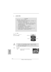
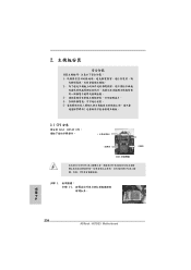
2 安全防范 1 2 3 4 5 2.1 CPU 安裝 要安裝 Intel 1155 針 CPU Load Plate Contact Array Load Lever Socket Body 1155 在您將 1155 針 CPU CPU CPU CPU 步驟 1. 1-1 簡體中文 216 ASRock H67DE3 Motherboard
2 安全防范 1 2 3 4 5 2.1 CPU 安裝 要安裝 Intel 1155 針 CPU Load Plate Contact Array Load Lever Socket Body 1155 在您將 1155 針 CPU CPU CPU CPU 步驟 1. 1-1 簡體中文 216 ASRock H67DE3 Motherboard

Quick Installation Guide
Page 217
步驟 1-2 135 步驟 1-3 100 步驟 2 1 2 步驟 3. 插入 1155 針 CPU: 步驟 3-1. 拿著 CPU 黑線 步驟 3-2. 將有 IHS (Integrated Heat Sink 1 基準標誌 第1針 1155 針 CPU 1155 針插槽 第1針 CPU 步驟 3-3 CPU 步驟 3-4. 檢查 CPU 217 ASRock H67DE3 Motherboard 簡體中文
步驟 1-2 135 步驟 1-3 100 步驟 2 1 2 步驟 3. 插入 1155 針 CPU: 步驟 3-1. 拿著 CPU 黑線 步驟 3-2. 將有 IHS (Integrated Heat Sink 1 基準標誌 第1針 1155 針 CPU 1155 針插槽 第1針 CPU 步驟 3-3 CPU 步驟 3-4. 檢查 CPU 217 ASRock H67DE3 Motherboard 簡體中文

Quick Installation Guide
Page 218
步驟 4. 4-1 IHS 4-2 4-3 2.2 CPU CPU 1155 針 CPU 1 IHS Apply Thermal Interface Material 步驟 2. 步驟 3. 步驟 4. CPU C.C.O CPU LGA775,LGA1155 與 LGA1156 LGA1155/1156 CPU 簡體中文 218 ASRock H67DE3 Motherboard CPU CPU_FAN1 2 頁 第 35 項)。 Fan cables on side closest to MB header Fastener slots pointing...
步驟 4. 4-1 IHS 4-2 4-3 2.2 CPU CPU 1155 針 CPU 1 IHS Apply Thermal Interface Material 步驟 2. 步驟 3. 步驟 4. CPU C.C.O CPU LGA775,LGA1155 與 LGA1156 LGA1155/1156 CPU 簡體中文 218 ASRock H67DE3 Motherboard CPU CPU_FAN1 2 頁 第 35 項)。 Fan cables on side closest to MB header Fastener slots pointing...
Quick Installation Guide
Page 238
2 安全防範 1 2 3 4 5 2.1 CPU 安裝 要安裝 Intel 1155 針 CPU Load Plate Contact Array Load Lever Socket Body ( 插槽 ) 1155 在您將 1155 針 CPU CPU CPU CPU 步驟 1. 1-1 繁體中文 238 ASRock H67DE3 Motherboard
2 安全防範 1 2 3 4 5 2.1 CPU 安裝 要安裝 Intel 1155 針 CPU Load Plate Contact Array Load Lever Socket Body ( 插槽 ) 1155 在您將 1155 針 CPU CPU CPU CPU 步驟 1. 1-1 繁體中文 238 ASRock H67DE3 Motherboard

