User Manual
Page 11
... in off mode condition. According to de ne the power consumption for more details. 11 According to adopt three different CPU cooler types, Socket LGA 775, LGA 1155 and LGA 1156. To meet the standard of the completed system shall be used. 17. Please be noticed that not all the 775 and...
... in off mode condition. According to de ne the power consumption for more details. 11 According to adopt three different CPU cooler types, Socket LGA 775, LGA 1155 and LGA 1156. To meet the standard of the completed system shall be used. 17. Please be noticed that not all the 775 and...
User Manual
Page 12
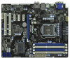
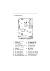
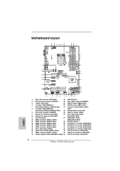
...REAR SPK Bottom: Optical SPDIF Top: LINE IN Center: FRONT Bottom: MIC IN Designed in Taipei CHA_FAN1 CPU_FAN2 CPU_FAN1 34 CHA_FAN3 CHA_FAN2 33 LAN PHY H67DE3 7 8 32 PCIE1 PCI Express 2.0 CMOS ErP/EuP Ready 31 PCIE2 Battery USB 3.0 30 Super I/O PCIE3 Intel 9 H67 SATA3 6Gb/s 29... 19 18 17 16 15 1 Power Fan Connector (PWR_FAN1) 19 64Mb SPI Flash 2 ATX 12V Power Connector (ATX12V1) 20 Clear CMOS Jumper (CLRCMOS1) 3 1155-Pin CPU Socket 21 USB 2.0 Header (USB8_9, Blue) 4 2 x 240-pin DDR3 DIMM Slots 22 USB 2.0 Header (USB6_7, Blue) (Dual Channel: DDR3_A1, DDR3_B1, ...
...REAR SPK Bottom: Optical SPDIF Top: LINE IN Center: FRONT Bottom: MIC IN Designed in Taipei CHA_FAN1 CPU_FAN2 CPU_FAN1 34 CHA_FAN3 CHA_FAN2 33 LAN PHY H67DE3 7 8 32 PCIE1 PCI Express 2.0 CMOS ErP/EuP Ready 31 PCIE2 Battery USB 3.0 30 Super I/O PCIE3 Intel 9 H67 SATA3 6Gb/s 29... 19 18 17 16 15 1 Power Fan Connector (PWR_FAN1) 19 64Mb SPI Flash 2 ATX 12V Power Connector (ATX12V1) 20 Clear CMOS Jumper (CLRCMOS1) 3 1155-Pin CPU Socket 21 USB 2.0 Header (USB8_9, Blue) 4 2 x 240-pin DDR3 DIMM Slots 22 USB 2.0 Header (USB6_7, Blue) (Dual Channel: DDR3_A1, DDR3_B1, ...
User Manual
Page 16
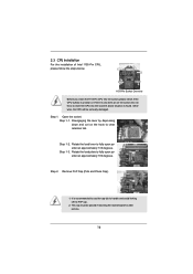
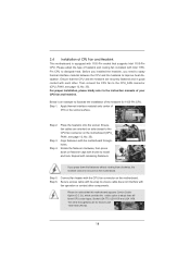
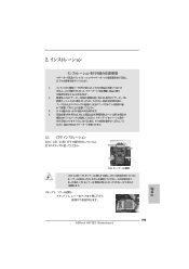
.... 2. Load Plate Load Lever Contact Array Socket Body 1155-Pin Socket Overview Before you insert the 1155-Pin CPU into the socket if above situation is found. 2.3 CPU Installation For the installation of Intel 1155-Pin CPU, please follow the steps below. Open the socket: Step 1-1. Do not force to insert... the CPU into the socket, please check if the CPU surface is unclean or if there is recommended ...
.... 2. Load Plate Load Lever Contact Array Socket Body 1155-Pin Socket Overview Before you insert the 1155-Pin CPU into the socket if above situation is found. 2.3 CPU Installation For the installation of Intel 1155-Pin CPU, please follow the steps below. Open the socket: Step 1-1. Do not force to insert... the CPU into the socket, please check if the CPU surface is unclean or if there is recommended ...

User Manual
Page 17
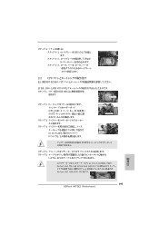
...notches. Rotate the load plate onto the IHS. Step 4. Step 3. Step 3-4. Close the socket: Step 4-1. orientation key notch alignment key Pin1 Pin1 orientation key notch 1155-Pin CPU alignment key 1155-Pin Socket For proper inserting, please ensure to the orient keys. Verify that the CPU is marked ...3-3. While pressing down lightly on load plate, engage the load lever. 17 Insert the 1155-Pin CPU: Step 3-1. Carefully place the CPU into the socket by the edge where is within the socket and properly mated to match the two orientation key notches of the CPU with IHS ...
...notches. Rotate the load plate onto the IHS. Step 4. Step 3. Step 3-4. Close the socket: Step 4-1. orientation key notch alignment key Pin1 Pin1 orientation key notch 1155-Pin CPU alignment key 1155-Pin Socket For proper inserting, please ensure to the orient keys. Verify that the CPU is marked ...3-3. While pressing down lightly on load plate, engage the load lever. 17 Insert the 1155-Pin CPU: Step 3-1. Carefully place the CPU into the socket by the edge where is within the socket and properly mated to match the two orientation key notches of the CPU with IHS ...
User Manual
Page 18
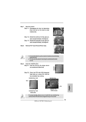
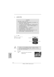
.... Please be secured on the motherboard. Then connect the CPU fan to adopt three different CPU cooler types, Socket LGA 775, LGA 1155 and LGA 1156. Repeat with 1155-Pin socket that the CPU and the heatsink are securely fastened and in good contact with Intel 1155Pin CPU to the CPU... to the CPU_FAN connector (CPU_FAN1, see page 12, No. 35). Please adopt the type of the heatsink for Socket LGA 1155/1156 CPU fan. 18 Ensure that supports Intel 1155-Pin CPU. Apply thermal interface material onto center of IHS on fastener caps with tie-wrap to illustrate the installation...
.... Please be secured on the motherboard. Then connect the CPU fan to adopt three different CPU cooler types, Socket LGA 775, LGA 1155 and LGA 1156. Repeat with 1155-Pin socket that the CPU and the heatsink are securely fastened and in good contact with Intel 1155Pin CPU to the CPU... to the CPU_FAN connector (CPU_FAN1, see page 12, No. 35). Please adopt the type of the heatsink for Socket LGA 1155/1156 CPU fan. 18 Ensure that supports Intel 1155-Pin CPU. Apply thermal interface material onto center of IHS on fastener caps with tie-wrap to illustrate the installation...
Quick Installation Guide
Page 2
... LINE IN Center: FRONT Bottom: MIC IN Designed in Taipei CHA_FAN1 CPU_FAN2 CPU_FAN1 34 CHA_FAN3 CHA_FAN2 33 LAN PHY H67DE3 7 8 32 PCIE1 PCI Express 2.0 CMOS ErP/EuP Ready 31 PCIE2 Battery USB 3.0 30 Super I/O PCIE3 Intel... Power Fan Connector (PWR_FAN1) 19 64Mb SPI Flash 2 ATX 12V Power Connector (ATX12V1) 20 Clear CMOS Jumper (CLRCMOS1) 3 1155-Pin CPU Socket 21 USB 2.0 Header (USB8_9, Blue) 4 2 x 240-pin DDR3 DIMM Slots 22 USB 2.0 Header (USB6_7, Blue) ...18 Chassis Speaker Header (SPEAKER 1, White) 35 CPU Fan Connector (CPU_FAN1) 2 ASRock H67DE3 Motherboard English
... LINE IN Center: FRONT Bottom: MIC IN Designed in Taipei CHA_FAN1 CPU_FAN2 CPU_FAN1 34 CHA_FAN3 CHA_FAN2 33 LAN PHY H67DE3 7 8 32 PCIE1 PCI Express 2.0 CMOS ErP/EuP Ready 31 PCIE2 Battery USB 3.0 30 Super I/O PCIE3 Intel... Power Fan Connector (PWR_FAN1) 19 64Mb SPI Flash 2 ATX 12V Power Connector (ATX12V1) 20 Clear CMOS Jumper (CLRCMOS1) 3 1155-Pin CPU Socket 21 USB 2.0 Header (USB8_9, Blue) 4 2 x 240-pin DDR3 DIMM Slots 22 USB 2.0 Header (USB6_7, Blue) ...18 Chassis Speaker Header (SPEAKER 1, White) 35 CPU Fan Connector (CPU_FAN1) 2 ASRock H67DE3 Motherboard English

Quick Installation Guide
Page 11
... the completed system. 16. EuP, stands for Energy Using Product, was a provision regulated by European Union to adopt three different CPU cooler types, Socket LGA 775, LGA 1155 and LGA 1156. To meet the standard of the completed system shall be used. 17. Please be noticed that not all the 775 and... than 50% under 1.00W in off mode condition. Combo Cooler Option (C.C.O.) provides the exible option to de ne the power consumption for more details. 11 ASRock H67DE3 Motherboard English
... the completed system. 16. EuP, stands for Energy Using Product, was a provision regulated by European Union to adopt three different CPU cooler types, Socket LGA 775, LGA 1155 and LGA 1156. To meet the standard of the completed system shall be used. 17. Please be noticed that not all the 775 and... than 50% under 1.00W in off mode condition. Combo Cooler Option (C.C.O.) provides the exible option to de ne the power consumption for more details. 11 ASRock H67DE3 Motherboard English
Quick Installation Guide
Page 12
...do not touch the ICs. 4. erboard to the motherboard, peripherals, and/or components. 2. Load Plate Contact Array Load Lever Socket Body 1155-Pin Socket Overview Before you install motherboard components or change any component, place it on a grounded antstatic pad or in the bag that comes.... To avoid damaging the motherboard components due to secure the moth- Whenever you handle components. 3. English 12 ASRock H67DE3 Motherboard When placing screws into the socket if above situation is any component. Do not force to insert the CPU into the screw holes to static electricity...
...do not touch the ICs. 4. erboard to the motherboard, peripherals, and/or components. 2. Load Plate Contact Array Load Lever Socket Body 1155-Pin Socket Overview Before you install motherboard components or change any component, place it on a grounded antstatic pad or in the bag that comes.... To avoid damaging the motherboard components due to secure the moth- Whenever you handle components. 3. English 12 ASRock H67DE3 Motherboard When placing screws into the socket if above situation is any component. Do not force to insert the CPU into the screw holes to static electricity...
Quick Installation Guide
Page 13
...the two orientation key notches of the CPU with the two alignment keys of the socket. 13 ASRock H67DE3 Motherboard English Orient the CPU with black lines. Step 1-3. Step 3. Step 1-2. black line Step 3-2. Insert the 1155-Pin CPU: Step 3-1. Step 1. Hold the CPU by depressing down and out...135 degrees. Rotate the load lever to clear retention tab. orientation key notch alignment key Pin1 Pin1 orientation key notch 1155-Pin CPU alignment key 1155-Pin Socket For proper inserting, please ensure to handle and avoid kicking off the PnP cap. 2. Disengaging the lever by ...
...the two orientation key notches of the CPU with the two alignment keys of the socket. 13 ASRock H67DE3 Motherboard English Orient the CPU with black lines. Step 1-3. Step 3. Step 1-2. black line Step 3-2. Insert the 1155-Pin CPU: Step 3-1. Step 1. Hold the CPU by depressing down and out...135 degrees. Rotate the load lever to clear retention tab. orientation key notch alignment key Pin1 Pin1 orientation key notch 1155-Pin CPU alignment key 1155-Pin Socket For proper inserting, please ensure to handle and avoid kicking off the PnP cap. 2. Disengaging the lever by ...

Quick Installation Guide
Page 14
... to illustrate the installation of IHS on fastener caps with remaining fasteners. Step 4-2. Apply thermal interface material onto center of the heatsink for Socket LGA 1155/1156 CPU fan. 14 ASRock H67DE3 Motherboard English Below is within the socket and properly mated to the CPU fan connector on the motherboard. Ensure fan cables are for...
... to illustrate the installation of IHS on fastener caps with remaining fasteners. Step 4-2. Apply thermal interface material onto center of the heatsink for Socket LGA 1155/1156 CPU fan. 14 ASRock H67DE3 Motherboard English Below is within the socket and properly mated to the CPU fan connector on the motherboard. Ensure fan cables are for...
Quick Installation Guide
Page 173
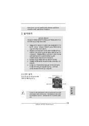
EuP 2 1 2 3 IC 4 5 2.1 CPU 설치 Intel 1155 핀 CPU 장착판 Load Plate Load Lever Contact Array Socket Body 1155 1155 핀 CPU CPU CPU CPU 한국어 173 ASRock H67DE3 Motherboard
EuP 2 1 2 3 IC 4 5 2.1 CPU 설치 Intel 1155 핀 CPU 장착판 Load Plate Load Lever Contact Array Socket Body 1155 1155 핀 CPU CPU CPU CPU 한국어 173 ASRock H67DE3 Motherboard
Quick Installation Guide
Page 195
1. 2. 3. IC 4. 2.1 CPU Intel 1155-LAND CPU Load Plate Load Lever Contact Array Socket Body 1155 1155-LAND CPU CPU CPU CPU 1 1-1 日本語 195 ASRock H67DE3 Motherboard
1. 2. 3. IC 4. 2.1 CPU Intel 1155-LAND CPU Load Plate Load Lever Contact Array Socket Body 1155 1155-LAND CPU CPU CPU CPU 1 1-1 日本語 195 ASRock H67DE3 Motherboard
Quick Installation Guide
Page 197
4 4-1 HIS 4-2 4-3 2.2 CPU CPU 以下は、1155-LAND CPU 1 HIS Apply Thermal Interface Material 2 CPU_FAN1、2 No. 35 CPU 3 4 Fan cables on side closest to MB header Fastener slots pointing straight out Press Down (4 Places) 5 CPU 6 C.C.O Socket LGA 775、LGA 1155 と LGA 1156 の 3 CPU Socket LGA 1155/1156 CPU 日本語 197 ASRock H67DE3 Motherboard
4 4-1 HIS 4-2 4-3 2.2 CPU CPU 以下は、1155-LAND CPU 1 HIS Apply Thermal Interface Material 2 CPU_FAN1、2 No. 35 CPU 3 4 Fan cables on side closest to MB header Fastener slots pointing straight out Press Down (4 Places) 5 CPU 6 C.C.O Socket LGA 775、LGA 1155 と LGA 1156 の 3 CPU Socket LGA 1155/1156 CPU 日本語 197 ASRock H67DE3 Motherboard
Quick Installation Guide
Page 216
2 安全防范 1 2 3 4 5 2.1 CPU 安裝 要安裝 Intel 1155 針 CPU Load Plate Contact Array Load Lever Socket Body 1155 在您將 1155 針 CPU CPU CPU CPU 步驟 1. 1-1 簡體中文 216 ASRock H67DE3 Motherboard
2 安全防范 1 2 3 4 5 2.1 CPU 安裝 要安裝 Intel 1155 針 CPU Load Plate Contact Array Load Lever Socket Body 1155 在您將 1155 針 CPU CPU CPU CPU 步驟 1. 1-1 簡體中文 216 ASRock H67DE3 Motherboard
Quick Installation Guide
Page 238
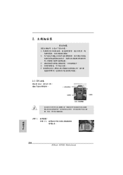
2 安全防範 1 2 3 4 5 2.1 CPU 安裝 要安裝 Intel 1155 針 CPU Load Plate Contact Array Load Lever Socket Body ( 插槽 ) 1155 在您將 1155 針 CPU CPU CPU CPU 步驟 1. 1-1 繁體中文 238 ASRock H67DE3 Motherboard
2 安全防範 1 2 3 4 5 2.1 CPU 安裝 要安裝 Intel 1155 針 CPU Load Plate Contact Array Load Lever Socket Body ( 插槽 ) 1155 在您將 1155 針 CPU CPU CPU CPU 步驟 1. 1-1 繁體中文 238 ASRock H67DE3 Motherboard