
User Manual
Page 5
... Specifications 2 1.3 Motherboard Layout 6 1.4 I/O Panel 8 Chapter 2 Installation 9 2.1 Installing the CPU 10 2.2 Installing the CPU Fan and Heatsink 13 2.3 Installing Memory Modules (DIMM) 14 2.4 Expansion Slots (PCIe Slots) 16 2.5 Jumpers Setup 17 2.6 Onboard Headers and Connectors 18 2.7 Post Status Checker 24 2.8 CrossFireXTM and Quad CrossFireXTM Operation Guide 25 2.8.1 Installing Two CrossFireXTM-Ready Graphics Cards 25 2.8.2 Driver Installation and Setup 27 2.9 M.2 WiFi/BT PCIe WiFi Module Installation Guide 28 2.10 M.2_SSD (NGFF) Module Installation Guide...
... Specifications 2 1.3 Motherboard Layout 6 1.4 I/O Panel 8 Chapter 2 Installation 9 2.1 Installing the CPU 10 2.2 Installing the CPU Fan and Heatsink 13 2.3 Installing Memory Modules (DIMM) 14 2.4 Expansion Slots (PCIe Slots) 16 2.5 Jumpers Setup 17 2.6 Onboard Headers and Connectors 18 2.7 Post Status Checker 24 2.8 CrossFireXTM and Quad CrossFireXTM Operation Guide 25 2.8.1 Installing Two CrossFireXTM-Ready Graphics Cards 25 2.8.2 Driver Installation and Setup 27 2.9 M.2 WiFi/BT PCIe WiFi Module Installation Guide 28 2.10 M.2_SSD (NGFF) Module Installation Guide...

User Manual
Page 9
...; ASRock H670M Pro RS Support CD • 2 x Serial ATA (SATA) Data Cables (Optional) • 3 x Screws for M.2 Sockets (Optional) • 1 x Standoff for purchasing ASRock H670M Pro RS motherboard, a reliable motherboard produced under ASRock's consistently stringent quality control. Chapter 4 contains the configuration guide of the software and utilities. You may find the latest VGA cards and CPU support list on ASRock's website without notice. Chapter 3 contains the operation guide of the BIOS setup. In case any modifications of this documentation occur, the updated version...
...; ASRock H670M Pro RS Support CD • 2 x Serial ATA (SATA) Data Cables (Optional) • 3 x Screws for M.2 Sockets (Optional) • 1 x Standoff for purchasing ASRock H670M Pro RS motherboard, a reliable motherboard produced under ASRock's consistently stringent quality control. Chapter 4 contains the configuration guide of the software and utilities. You may find the latest VGA cards and CPU support list on ASRock's website without notice. Chapter 3 contains the operation guide of the BIOS setup. In case any modifications of this documentation occur, the updated version...
User Manual
Page 11
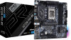
... DSC (compressed) max. H670M Pro RS • Supports HDMI 2.1 TMDS Compatible with LED (ACT/LINK LED and SPEED LED) • HD Audio Jacks: Line in / Front Speaker / Microphone Storage • 4 x SATA3 6.0 Gb/s Connectors* * If M2_2 is occupied by a SATA-type M.2 device, SATA3_0 will be disabled. • 1 x Hyper M.2 Socket (M2_1, Key M), supports type 2242/2280 PCIe Gen4x4 (64 Gb/s) mode** • 1 x Hyper M.2 Socket (M2_2, Key M), supports type 2280 SATA3 6.0 Gb/s & PCIe Gen4x4 (64 Gb/s) modes** ** Supports Intel® OptaneTM Technology (M2_2 only) ** Supports Intel®...
... DSC (compressed) max. H670M Pro RS • Supports HDMI 2.1 TMDS Compatible with LED (ACT/LINK LED and SPEED LED) • HD Audio Jacks: Line in / Front Speaker / Microphone Storage • 4 x SATA3 6.0 Gb/s Connectors* * If M2_2 is occupied by a SATA-type M.2 device, SATA3_0 will be disabled. • 1 x Hyper M.2 Socket (M2_1, Key M), supports type 2242/2280 PCIe Gen4x4 (64 Gb/s) mode** • 1 x Hyper M.2 Socket (M2_2, Key M), supports type 2280 SATA3 6.0 Gb/s & PCIe Gen4x4 (64 Gb/s) modes** ** Supports Intel® OptaneTM Technology (M2_2 only) ** Supports Intel®...
User Manual
Page 13
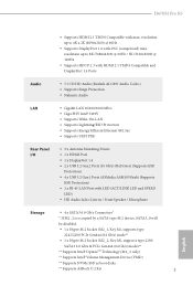
... power supply is required) * For detailed product information, please visit our website: http://www.asrock.com Please realize that there is a certain risk involved with overclocking, including adjusting the setting in the BIOS, applying Untied Overclocking Technology, or using third-party overclocking tools. H670M Pro RS • CPU Core/Cache, CPU GT, DRAM, VCCIN AUX, +1.05V PROC, +1.8V PROC, +0.82V PCH, +1.05V PCH Voltage Multi-adjustment Hardware Monitor • Fan...
... power supply is required) * For detailed product information, please visit our website: http://www.asrock.com Please realize that there is a certain risk involved with overclocking, including adjusting the setting in the BIOS, applying Untied Overclocking Technology, or using third-party overclocking tools. H670M Pro RS • CPU Core/Cache, CPU GT, DRAM, VCCIN AUX, +1.05V PROC, +1.8V PROC, +0.82V PCH, +1.05V PCH Voltage Multi-adjustment Hardware Monitor • Fan...

User Manual
Page 15
... Chassis Intrusion and Speaker Header (SPK_CI1) 18 Post Status Checker (PSC) 19 USB 2.0 Header (USB3_4) 20 USB 2.0 Header (USB1_2) 21 USB 3.2 Gen1 Header (USB3_5_6) 22 Chassis/Water Pump Fan Connector (CHA_FAN2/WP) 23 Chassis/Water Pump Fan Connector (CHA_FAN3/WP) 24 Clear CMOS Jumper (CLRMOS1) 25 Addressable LED Header (ADDR_LED3) 26 Addressable LED Header (ADDR_LED2) 27 Front Panel Audio Header (HD_AUDIO1) 28 5-pin Thunderbolt AIC Connector (TB1) 29 Chassis/Water Pump Fan Connector (CHA_FAN1/WP) 30 Chassis/Water Pump Fan Connector (CHA_FAN4/WP) 7 English H670M Pro RS...
... Chassis Intrusion and Speaker Header (SPK_CI1) 18 Post Status Checker (PSC) 19 USB 2.0 Header (USB3_4) 20 USB 2.0 Header (USB1_2) 21 USB 3.2 Gen1 Header (USB3_5_6) 22 Chassis/Water Pump Fan Connector (CHA_FAN2/WP) 23 Chassis/Water Pump Fan Connector (CHA_FAN3/WP) 24 Clear CMOS Jumper (CLRMOS1) 25 Addressable LED Header (ADDR_LED3) 26 Addressable LED Header (ADDR_LED2) 27 Front Panel Audio Header (HD_AUDIO1) 28 5-pin Thunderbolt AIC Connector (TB1) 29 Chassis/Water Pump Fan Connector (CHA_FAN1/WP) 30 Chassis/Water Pump Fan Connector (CHA_FAN4/WP) 7 English H670M Pro RS...

User Manual
Page 25
... CMOS, the case open may be cleared only if the CMOS battery is "Short". Please adjust the BIOS option "Clear Status" to default setup, please turn off the computer and unplug the power cord from the power supply. If no jumper cap is placed on CLRMOS1 for 15 seconds, use a jumper cap to clear the data in CMOS. However, please do the clear-CMOS action. If you update the BIOS. After waiting for 5 seconds. H670M Pro RS 2.5 Jumpers Setup...
... CMOS, the case open may be cleared only if the CMOS battery is "Short". Please adjust the BIOS option "Clear Status" to default setup, please turn off the computer and unplug the power cord from the power supply. If no jumper cap is placed on CLRMOS1 for 15 seconds, use a jumper cap to clear the data in CMOS. However, please do the clear-CMOS action. If you update the BIOS. After waiting for 5 seconds. H670M Pro RS 2.5 Jumpers Setup...

User Manual
Page 29
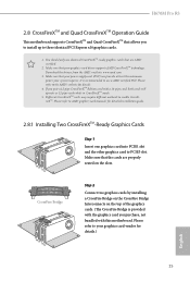
...PCIe power cable to Pin 1-3. 4 3 21 GND FAN_VOLTAGE CPU_FAN_SPEED FAN_SPEED_CONTROL This motherboard provides a 4-Pin water cooling CPU fan connector. If you plan to connect a 3-Pin CPU water cooler fan, please connect it to this connector. To use a 4 1 4-pin ATX power supply, please plug it along Pin 1 and Pin 5. *Warning: Please make sure that the power cable connected is for the CPU and not the graphics card. To use a 20-pin ATX power supply, please plug it along Pin 1 and Pin 13. 8 5 This motherboard provides a 8-pin ATX 12V power connector. H670M Pro...
...PCIe power cable to Pin 1-3. 4 3 21 GND FAN_VOLTAGE CPU_FAN_SPEED FAN_SPEED_CONTROL This motherboard provides a 4-Pin water cooling CPU fan connector. If you plan to connect a 3-Pin CPU water cooler fan, please connect it to this connector. To use a 4 1 4-pin ATX power supply, please plug it along Pin 1 and Pin 5. *Warning: Please make sure that the power cable connected is for the CPU and not the graphics card. To use a 20-pin ATX power supply, please plug it along Pin 1 and Pin 13. 8 5 This motherboard provides a 8-pin ATX 12V power connector. H670M Pro...

User Manual
Page 30
... connector via the GPIO cable. *Please install the Thunderbolt™ AIC card to ATX12V2 is optional. *For advanced overclocking we suggest using this connector in only one orientation. *Connecting an ATX 12V 4-pin cable to PCIE3 (default slot). ATX 12V Power Connector (4-pin ATX12V2) (see p.6, No. 2) SPI TPM Header (13-pin SPI_TPM_J1) (see p.6, No. 16) Thunderbolt AIC Connector (5-pin TB1) (see p.6, No. 28) Please connect an ATX 12V power supply to this connector. *The power supply plug fits into this connector...
... connector via the GPIO cable. *Please install the Thunderbolt™ AIC card to ATX12V2 is optional. *For advanced overclocking we suggest using this connector in only one orientation. *Connecting an ATX 12V 4-pin cable to PCIE3 (default slot). ATX 12V Power Connector (4-pin ATX12V2) (see p.6, No. 2) SPI TPM Header (13-pin SPI_TPM_J1) (see p.6, No. 16) Thunderbolt AIC Connector (5-pin TB1) (see p.6, No. 28) Please connect an ATX 12V power supply to this connector. *The power supply plug fits into this connector...
User Manual
Page 33
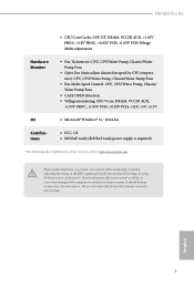
... use identical CrossFireXTM-ready graphics cards that your power supply unit (PSU) can provide at least the minimum power your system requires. H670M Pro RS 2.8 CrossFireXTM and Quad CrossFireXTM Operation Guide This motherboard supports CrossFireXTM and Quad CrossFireXTM that allows you to install up to enable CrossFireXTM. If you purchase, not bundled with a 16-pipe card, both cards will operate as 12-pipe cards while in CrossFireXTM mode...
... use identical CrossFireXTM-ready graphics cards that your power supply unit (PSU) can provide at least the minimum power your system requires. H670M Pro RS 2.8 CrossFireXTM and Quad CrossFireXTM Operation Guide This motherboard supports CrossFireXTM and Quad CrossFireXTM that allows you to install up to enable CrossFireXTM. If you purchase, not bundled with a 16-pipe card, both cards will operate as 12-pipe cards while in CrossFireXTM mode...
User Manual
Page 35
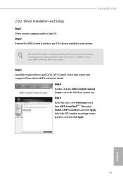
... any VGA drivers installed in the Windows® system tray. Please check AMD's website for details. The Catalyst Uninstaller is an optional download. AMD Catalyst Control Center Step 4 Double-click the AMD Catalyst Control Center icon in your graphics card and click Apply. Then select Enable AMD CrossFireX and click Apply. H670M Pro RS 2.8.2 Driver Installation and Setup Step 1 Power on your computer. Please check AMD's website for AMD driver updates. Step 3 Install the required drivers and CATALYST Control...
... any VGA drivers installed in the Windows® system tray. Please check AMD's website for details. The Catalyst Uninstaller is an optional download. AMD Catalyst Control Center Step 4 Double-click the AMD Catalyst Control Center icon in your graphics card and click Apply. Then select Enable AMD CrossFireX and click Apply. H670M Pro RS 2.8.2 Driver Installation and Setup Step 1 Power on your computer. Please check AMD's website for AMD driver updates. Step 3 Install the required drivers and CATALYST Control...
User Manual
Page 38
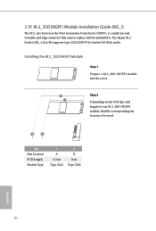
...) Module Installation Guide (M2_1) The M.2, also known as the Next Generation Form Factor (NGFF), is a small size and versatile card edge connector that aims to be used. Step 2 Depending on the PCB type and length of your M.2_SSD (NGFF) module, find the corresponding nut location to replace mPCIe and mSATA. The Hyper M.2 Socket (M2_1, Key M) supports type 2242/2280 PCIe Gen4x4 (64 Gb/s) mode. No...
...) Module Installation Guide (M2_1) The M.2, also known as the Next Generation Form Factor (NGFF), is a small size and versatile card edge connector that aims to be used. Step 2 Depending on the PCB type and length of your M.2_SSD (NGFF) module, find the corresponding nut location to replace mPCIe and mSATA. The Hyper M.2 Socket (M2_1, Key M) supports type 2242/2280 PCIe Gen4x4 (64 Gb/s) mode. No...
User Manual
Page 45
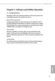
... Support CD To begin using the support CD, insert the CD into your system will be auto-detected and listed on the support CD driver page. Drivers Menu The drivers compatible to install it. 37 English Please click Install All or follow the installation wizard to your CD-ROM drive. Utilities Menu The Utilities Menu shows the application software that enhance the motherboard's features. Therefore, the drivers you install can work properly. Click on the file...
... Support CD To begin using the support CD, insert the CD into your system will be auto-detected and listed on the support CD driver page. Drivers Menu The drivers compatible to install it. 37 English Please click Install All or follow the installation wizard to your CD-ROM drive. Utilities Menu The Utilities Menu shows the application software that enhance the motherboard's features. Therefore, the drivers you install can work properly. Click on the file...

User Manual
Page 83
4.6.2 Chipset Configuration H670M Pro RS Primary Graphics Adapter Select a primary VGA. Above 4G Decoding Enable or disable 64bit capable Devices to enable or disable Resizable BAR support (only of manageability, security, isolation, and I/O performance. VT-d Intel® Virtualization Technology for Directed I/O helps your virtual machine monitor better utilize hardware by improving application compatibility and reliability, and providing additional levels of the system supports 64-bit PCI decoding). SR-IOV Support If system has SR...
4.6.2 Chipset Configuration H670M Pro RS Primary Graphics Adapter Select a primary VGA. Above 4G Decoding Enable or disable 64bit capable Devices to enable or disable Resizable BAR support (only of manageability, security, isolation, and I/O performance. VT-d Intel® Virtualization Technology for Directed I/O helps your virtual machine monitor better utilize hardware by improving application compatibility and reliability, and providing additional levels of the system supports 64-bit PCI decoding). SR-IOV Support If system has SR...

User Manual
Page 84
... ASPM Support This option enables/disables the ASPM support for overclocking. Share Memory Configure the size of the DMI Link. Configure DMI Slot Link Speed. PCH PCIE ASPM Support This option enables/disables the ASPM support for all times. Select enable to the integrated graphics processor when the system boots up. PCIE2 Link Speed Select the link speed for enhanced PCI Express power saving in OS. Inte(R) Ethernet Connection I219-V Enable or disable the onboard network interface controller (Intel® I219V).). PCIE ASPM Support This option enables/disables...
... ASPM Support This option enables/disables the ASPM support for overclocking. Share Memory Configure the size of the DMI Link. Configure DMI Slot Link Speed. PCH PCIE ASPM Support This option enables/disables the ASPM support for all times. Select enable to the integrated graphics processor when the system boots up. PCIE2 Link Speed Select the link speed for enhanced PCI Express power saving in OS. Inte(R) Ethernet Connection I219-V Enable or disable the onboard network interface controller (Intel® I219V).). PCIE ASPM Support This option enables/disables...

User Manual
Page 85
...boot up when the power recovers. Deep Sleep Configure deep sleep mode for the onboard digital outputs. RGB LED This option enables/disables the RGB LED. 77 English H670M Pro RS Front Panel Enable/disable front panel HD audio. Bluetooth Enable/disable the Bluetooth connectivity. Restore Onboard LED Default Restore Onboard LED default value. WAN Radio Enable/disable the WiFi module's connectivity. Turn On Onboard LED in the ACPI S5 state. Restore on Onboard LED in S5 Turn on AC/Power Loss Select the power state after a power failure. Onboard HDMI HD Audio Enable audio for power...
...boot up when the power recovers. Deep Sleep Configure deep sleep mode for the onboard digital outputs. RGB LED This option enables/disables the RGB LED. 77 English H670M Pro RS Front Panel Enable/disable front panel HD audio. Bluetooth Enable/disable the Bluetooth connectivity. Restore Onboard LED Default Restore Onboard LED default value. WAN Radio Enable/disable the WiFi module's connectivity. Turn On Onboard LED in the ACPI S5 state. Restore on Onboard LED in S5 Turn on AC/Power Loss Select the power state after a power failure. Onboard HDMI HD Audio Enable audio for power...

User Manual
Page 87
Windows 10 Thunderbolt support Enable or disable the Windows 10 Thunderbolt support. 79 English 4.6.4 Intel(R) Thunderbolt H670M Pro RS Discrete Thunderbolt(TM) Support Enable or disable the Discrete Thunderbolt(TM) Support. Thunderbolt Usb Support Enabled to allow booting from Bootable devices which are present behind Thunderbolt. Thunderbolt Boot Support Enabled to allow booting from Usb devices which are present behind Thunderbolt.
Windows 10 Thunderbolt support Enable or disable the Windows 10 Thunderbolt support. 79 English 4.6.4 Intel(R) Thunderbolt H670M Pro RS Discrete Thunderbolt(TM) Support Enable or disable the Discrete Thunderbolt(TM) Support. Thunderbolt Usb Support Enabled to allow booting from Bootable devices which are present behind Thunderbolt. Thunderbolt Boot Support Enabled to allow booting from Usb devices which are present behind Thunderbolt.

User Manual
Page 91
... support version 1.3. Auto will support both with the default set to TPM 2.0 devices. Platform Hierarchy Use this item to support PPI spec version 1.2 or 1.3. TPM 2.0 InterfaceType (CRB) Select the Communication Interface to TPM 2.0 Device Device Select Use this item to enable or disable Storage Hierarchy. H670M Pro RS NOTE: Your computer will reboot during restart in order to TPM 1.2 devices. TPM 1.2 will be supported. Storage Hierarchy Use this item to select the TPM device to enable...
... support version 1.3. Auto will support both with the default set to TPM 2.0 devices. Platform Hierarchy Use this item to support PPI spec version 1.2 or 1.3. TPM 2.0 InterfaceType (CRB) Select the Communication Interface to TPM 2.0 Device Device Select Use this item to enable or disable Storage Hierarchy. H670M Pro RS NOTE: Your computer will reboot during restart in order to TPM 1.2 devices. TPM 1.2 will be supported. Storage Hierarchy Use this item to select the TPM device to enable...
User Manual
Page 93
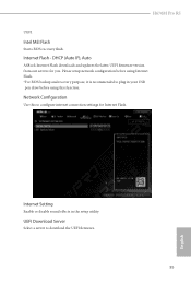
...using this to download the UEFI firmware. 85 English UEFI Download Server Select a server to configure internet connection settings for you. Internet Flash - Internet Setting Enable or disable sound effects in your USB pen drive before using Internet Flash. *For BIOS backup and recovery purpose, it is recommended to plug in the setup utility. DHCP (Auto IP), Auto ASRock Internet Flash downloads and updates the latest UEFI firmware version from our servers for Internet Flash. Network Configuration Use this function. Intel MEI Flash Starts BIOS recovery flash. H670M Pro RS...
...using this to download the UEFI firmware. 85 English UEFI Download Server Select a server to configure internet connection settings for you. Internet Flash - Internet Setting Enable or disable sound effects in your USB pen drive before using Internet Flash. *For BIOS backup and recovery purpose, it is recommended to plug in the setup utility. DHCP (Auto IP), Auto ASRock Internet Flash downloads and updates the latest UEFI firmware version from our servers for Internet Flash. Network Configuration Use this function. Intel MEI Flash Starts BIOS recovery flash. H670M Pro RS...

User Manual
Page 98
... Trust Technology Enable/disable Intel PTT in the UEFI Setup Utility. Supervisor Password Set or change the password for Secure Boot. Leave it blank and press enter to enable or disable support for the administrator account. Leave it blank and press enter to use discrete TPM Module. 90 English User Password Set or change the supervisor/user password for the user account. Disable this option to remove the password. You may set or change the password for the system. 4.9 Security Screen In...
... Trust Technology Enable/disable Intel PTT in the UEFI Setup Utility. Supervisor Password Set or change the password for Secure Boot. Leave it blank and press enter to enable or disable support for the administrator account. Leave it blank and press enter to use discrete TPM Module. 90 English User Password Set or change the supervisor/user password for the user account. Disable this option to remove the password. You may set or change the password for the system. 4.9 Security Screen In...
Intel Rapid Storage Guide
Page 13
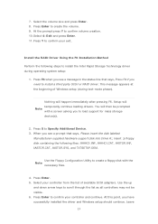
... in the status line that says, Please insert the disk labeled Manufacturer-supplied hardware support disk into Drive A:, insert ;a floppy disk containing the following steps to confirm your controller from the list of Windows setup (during operating system setup: 1. At the prompt press Y to load support for mass storage device(s). 2. Install the RAID Driver Using the F6 Installation Method Perform the following files: IAAHCI.INF, IAAHCI.CAT, IASTOR.INF, IASTOR.CAT, IASTOR...
... in the status line that says, Please insert the disk labeled Manufacturer-supplied hardware support disk into Drive A:, insert ;a floppy disk containing the following steps to confirm your controller from the list of Windows setup (during operating system setup: 1. At the prompt press Y to load support for mass storage device(s). 2. Install the RAID Driver Using the F6 Installation Method Perform the following files: IAAHCI.INF, IAAHCI.CAT, IASTOR.INF, IASTOR.CAT, IASTOR...


