User Manual
Page 2
...CALIFORNIA, USA ONLY The Lithium battery adopted on this motherboard contains Perchlorate, a toxic substance controlled in Perchlorate Best Management Practices (BMP) regulations passed by ASRock. With respect to the contents of this manual, ASRock does not provide warranty of any kind, either expressed...for informational use only and subject to the implied warranties or conditions of merchantability or itness for a particular purpose. ASRock assumes no event shall ASRock, its directors, oficers, employees, or agents be liable for any indirect, special, incidental, or consequential damages (...
...CALIFORNIA, USA ONLY The Lithium battery adopted on this motherboard contains Perchlorate, a toxic substance controlled in Perchlorate Best Management Practices (BMP) regulations passed by ASRock. With respect to the contents of this manual, ASRock does not provide warranty of any kind, either expressed...for informational use only and subject to the implied warranties or conditions of merchantability or itness for a particular purpose. ASRock assumes no event shall ASRock, its directors, oficers, employees, or agents be liable for any indirect, special, incidental, or consequential damages (...
User Manual
Page 3
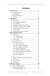
Contents 1 Introduction 4 1.1 Package Contents 4 1.2 Speciications 5 1.3 Motherboard Layout 8 1.4 I/O Panel 9 2 Installation 10 2.1 Screw Holes 10 2.2 Pre-installation Precautions 10 2.3 CPU Installation 11 2.4 Installation of Heatsink and CPU fan 13 2.5 Installation of Memory Modules (...
Contents 1 Introduction 4 1.1 Package Contents 4 1.2 Speciications 5 1.3 Motherboard Layout 8 1.4 I/O Panel 9 2 Installation 10 2.1 Screw Holes 10 2.2 Pre-installation Precautions 10 2.3 CPU Installation 11 2.4 Installation of Heatsink and CPU fan 13 2.5 Installation of Memory Modules (...
User Manual
Page 5
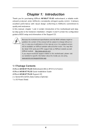
... subject to BIOS setup and information of the motherboard and stepby-step guide to quality and endurance. www.asrock.com/support/index.asp 1.1 Package Contents ASRock H61M-XT PLUS Motherboard (Micro ATX Form Factor) ASRock H61M-XT PLUS Quick Installation Guide ASRock H61M-XT PLUS Support CD 2 x Serial ATA (SATA) Data Cables (Optional) 1 x I/O Panel Shield 4 ASRock website http://www.asrock.com If you are using. You may...
... subject to BIOS setup and information of the motherboard and stepby-step guide to quality and endurance. www.asrock.com/support/index.asp 1.1 Package Contents ASRock H61M-XT PLUS Motherboard (Micro ATX Form Factor) ASRock H61M-XT PLUS Quick Installation Guide ASRock H61M-XT PLUS Support CD 2 x Serial ATA (SATA) Data Cables (Optional) 1 x I/O Panel Shield 4 ASRock website http://www.asrock.com If you are using. You may...
User Manual
Page 9
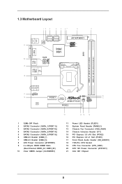
1.3 Motherboard Layout 12 3 4 5 67 8 9 SATA_0 (PORT 0) SATA_2 (PORT 4) PS2 Mouse PS2 Keyboard 32Mb BIOS SATA_1 (PORT 1) SATA_3 (PORT 5) 21 Intel H61 VGA1 RoHS 20 CPU_FAN1 USB 2.0 T: ... bit, 240-pin module) Top: LINE IN Center: FRONT Bottom: MIC IN 17 HD_AUDIO1 1 16 PCIE1 CMOS BATTERY CI1 1 1 CLRCMOS1 PLED1 1 PLED PWRBTN 10 11 H61M-XT PLUS CHA_FAN1 1 HDLED RESET PANEL1 AUDIO CODEC PCIE2 15 14 13 12 1 32Mb SPI Flash 2 SATA2 Connector (SATA_1 (PORT 1)) 3 SATA2 Connector (SATA_0 (PORT 0)) 4 SATA2 Connector (SATA_2...
1.3 Motherboard Layout 12 3 4 5 67 8 9 SATA_0 (PORT 0) SATA_2 (PORT 4) PS2 Mouse PS2 Keyboard 32Mb BIOS SATA_1 (PORT 1) SATA_3 (PORT 5) 21 Intel H61 VGA1 RoHS 20 CPU_FAN1 USB 2.0 T: ... bit, 240-pin module) Top: LINE IN Center: FRONT Bottom: MIC IN 17 HD_AUDIO1 1 16 PCIE1 CMOS BATTERY CI1 1 1 CLRCMOS1 PLED1 1 PLED PWRBTN 10 11 H61M-XT PLUS CHA_FAN1 1 HDLED RESET PANEL1 AUDIO CODEC PCIE2 15 14 13 12 1 32Mb SPI Flash 2 SATA2 Connector (SATA_1 (PORT 1)) 3 SATA2 Connector (SATA_0 (PORT 0)) 4 SATA2 Connector (SATA_2...
User Manual
Page 11
...grounded antistatic pad or in the bag that comes with the component. Failure to do so may cause physical injuries to you and damages to motherboard components. 2.1 Screw Holes Place screws into the holes indicated by the edges and do so may cause severe damage to unplug the power cord... electricity, NEVER place your chassis to the chassis. Hold components by circles to secure the motherboard to ensure that the power is switched off or the power cord is a Micro ATX form factor motherboard. Unplug the power cord from the power supply. Before you install or remove any component,...
...grounded antistatic pad or in the bag that comes with the component. Failure to do so may cause physical injuries to you and damages to motherboard components. 2.1 Screw Holes Place screws into the holes indicated by the edges and do so may cause severe damage to unplug the power cord... electricity, NEVER place your chassis to the chassis. Hold components by circles to secure the motherboard to ensure that the power is switched off or the power cord is a Micro ATX form factor motherboard. Unplug the power cord from the power supply. Before you install or remove any component,...
User Manual
Page 12
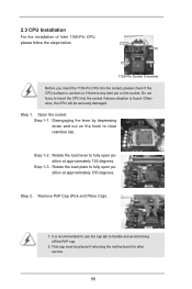
Otherwise, the CPU will be placed if returning the motherboard for after service. 11 Open the socket: Step 1-1. Disengaging the lever by depressing down and out on the socket. Rotate the load plate to clear ...
Otherwise, the CPU will be placed if returning the motherboard for after service. 11 Open the socket: Step 1-1. Disengaging the lever by depressing down and out on the socket. Rotate the load plate to clear ...

User Manual
Page 14
...wrap to ensure cable does not interfere with the CPU fan connector on the socket surface. 2.4 Installation of CPU Fan and Heatsink This motherboard is an example to illustrate the installation of the heatsink for 1155-Pin CPU. Then connect the CPU fan to the CPU_FAN connector (...securely fastened and in good contact with thumb to improve heat dissipation. Step 5. Before you installed the heatsink, you press down on the motherboard. Step 1. Rotate the fastener clockwise, then press down the fasteners without rotating them clockwise, the heatsink cannot be secured on fastener caps with...
...wrap to ensure cable does not interfere with the CPU fan connector on the socket surface. 2.4 Installation of CPU Fan and Heatsink This motherboard is an example to illustrate the installation of the heatsink for 1155-Pin CPU. Then connect the CPU fan to the CPU_FAN connector (...securely fastened and in good contact with thumb to improve heat dissipation. Step 5. Before you installed the heatsink, you press down on the motherboard. Step 1. Rotate the fastener clockwise, then press down the fasteners without rotating them clockwise, the heatsink cannot be secured on fastener caps with...
User Manual
Page 15
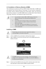
...removing DIMMs or the system components. Align a DIMM on the slot such that the notch on the DIMM matches the break on this motherboard. notch break notch break The DIMM only its in one memory module or two non-identical memory modules, it will cause permanent damage... will operate at incorrect orientation. Some DDR3 1GB double-sided DIMMs with 16 chips may be damaged. 2. 2.5 Installation of Memory Modules (DIMM) This motherboard provides two 240-pin DDR3 (Double Data Rate 3) DIMM slots, and supports Dual Channel Memory Technology. Installing a DIMM Please make sure to install them...
...removing DIMMs or the system components. Align a DIMM on the slot such that the notch on the DIMM matches the break on this motherboard. notch break notch break The DIMM only its in one memory module or two non-identical memory modules, it will cause permanent damage... will operate at incorrect orientation. Some DDR3 1GB double-sided DIMMs with 16 chips may be damaged. 2. 2.5 Installation of Memory Modules (DIMM) This motherboard provides two 240-pin DDR3 (Double Data Rate 3) DIMM slots, and supports Dual Channel Memory Technology. Installing a DIMM Please make sure to install them...

User Manual
Page 16
If you start the installation. Step 2. Keep the Step 4. Remove the system unit cover (if your motherboard is already installed in Gen 3 speed, please install an Ivy Bridge CPU. Fasten the card to use . Remove the bracket facing the slot that the ...power supply is switched off or the power cord is completely seated on this motherboard. Step 3. To run only at PCI Express Gen 2 speed. Replace the system cover. 15 Please read the documentation of the expansion card and make sure...
If you start the installation. Step 2. Keep the Step 4. Remove the system unit cover (if your motherboard is already installed in Gen 3 speed, please install an Ivy Bridge CPU. Fasten the card to use . Remove the bracket facing the slot that the ...power supply is switched off or the power cord is completely seated on this motherboard. Step 3. To run only at PCI Express Gen 2 speed. Replace the system cover. 15 Please read the documentation of the expansion card and make sure...
User Manual
Page 18
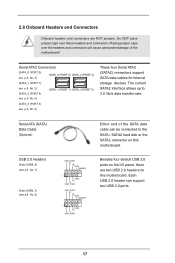
...support two USB 2.0 ports. 17 The current SATA2 interface allows up to the SATA / SATA2 hard disk or the SATA2 connector on this motherboard. Each USB 2.0 header can be connected to 3.0 Gb/s data transfer rate. Serial ATA2 Connectors (SATA_0 (PORT 0): see p.8, No. ...(SATA_3 (PORT 5): see p.8 No. 6) USB_PWR -B +B GND DUMMY 1 GND +A -A USB_PWR USB_PWR -B +B GND DUMMY 1 GND +A -A USB_PWR Either end of the motherboard! Placing jumper caps over these headers and connectors. Besides four default USB 2.0 ports on the I/O panel, there are NOT jumpers. Serial ATA (SATA) Data Cable...
...support two USB 2.0 ports. 17 The current SATA2 interface allows up to the SATA / SATA2 hard disk or the SATA2 connector on this motherboard. Each USB 2.0 header can be connected to 3.0 Gb/s data transfer rate. Serial ATA2 Connectors (SATA_0 (PORT 0): see p.8, No. ...(SATA_3 (PORT 5): see p.8 No. 6) USB_PWR -B +B GND DUMMY 1 GND +A -A USB_PWR USB_PWR -B +B GND DUMMY 1 GND +A -A USB_PWR Either end of the motherboard! Placing jumper caps over these headers and connectors. Besides four default USB 2.0 ports on the I/O panel, there are NOT jumpers. Serial ATA (SATA) Data Cable...
User Manual
Page 20
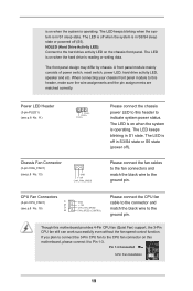
... and match the black wire to this header, make sure the wire assignments and the pin assign-ments are matched correctly. is on this motherboard, please connect it to Pin 1-3. If you plan to connect the 3-Pin CPU fan to the CPU fan connector on when the system ... system power status. CPU Fan Connectors (4-pin CPU_FAN1) 1 2 (see p.8 No. 13) GND + 12V CHA_ FAN_SPEED Please connect the chassis power LED to this motherboard provides 4-Pin CPU fan (Quiet Fan) support, the 3-Pin CPU fan still can work successfully even without the fan speed control function. A front panel module...
... and match the black wire to this header, make sure the wire assignments and the pin assign-ments are matched correctly. is on this motherboard, please connect it to Pin 1-3. If you plan to connect the 3-Pin CPU fan to the CPU fan connector on when the system ... system power status. CPU Fan Connectors (4-pin CPU_FAN1) 1 2 (see p.8 No. 13) GND + 12V CHA_ FAN_SPEED Please connect the chassis power LED to this motherboard provides 4-Pin CPU fan (Quiet Fan) support, the 3-Pin CPU fan still can work successfully even without the fan speed control function. A front panel module...
User Manual
Page 21
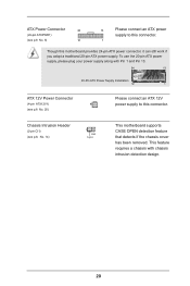
..., please plug your power supply along with chassis intrusion detection design. 20 Chassis Intrusion Header (2-pin CI1) (see p.8, No. 14) 1 GND Signal This motherboard supports CASE OPEN detection feature that detects if the chassis cover has been removed. This feature requires a chassis with Pin 1 and Pin 13. 24 13... ATX Power Supply Installation 12 1 ATX 12V Power Connector (4-pin ATX12V1) (see p.8 No. 8) 12 13 Please connect an ATX power supply to this motherboard provides 24-pin ATX power connector, it can still work if you adopt a traditional 20-pin ATX power supply.
..., please plug your power supply along with chassis intrusion detection design. 20 Chassis Intrusion Header (2-pin CI1) (see p.8, No. 14) 1 GND Signal This motherboard supports CASE OPEN detection feature that detects if the chassis cover has been removed. This feature requires a chassis with Pin 1 and Pin 13. 24 13... ATX Power Supply Installation 12 1 ATX 12V Power Connector (4-pin ATX12V1) (see p.8 No. 8) 12 13 Please connect an ATX power supply to this motherboard provides 24-pin ATX power connector, it can still work if you adopt a traditional 20-pin ATX power supply.
User Manual
Page 22
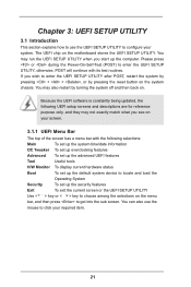
... by turning the system off and then back on the system chassis. The UEFI chip on your required item. 21 If you see on the motherboard stores the UEFI SETUP UTILITY. Please press or during the Power-On-Self-Test (POST) to conigure your system. Because the UEFI software is constantly...
... by turning the system off and then back on the system chassis. The UEFI chip on your required item. 21 If you see on the motherboard stores the UEFI SETUP UTILITY. Please press or during the Power-On-Self-Test (POST) to conigure your system. Because the UEFI software is constantly...
User Manual
Page 24
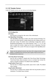
... Turbo Boost Mode Technology. Turbo Boost Mode allows processor cores to conigure long duration power limit in speciic conditions. Long Duration Power Limit Use this motherboard. Coniguration options: [Enabled] and [Disabled]. CPU Coniguration CPU Ratio Use this item to change the ratio value of this item to run faster than marked...
... Turbo Boost Mode Technology. Turbo Boost Mode allows processor cores to conigure long duration power limit in speciic conditions. Long Duration Power Limit Use this motherboard. Coniguration options: [Enabled] and [Disabled]. CPU Coniguration CPU Ratio Use this item to change the ratio value of this item to run faster than marked...
User Manual
Page 25
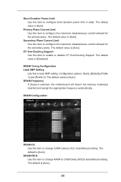
... Use this item to conigure the maximum instantaneous current allowed for the primary plane. The default value is [Auto]. The default value is selected, the motherboard will detect the memory module(s) inserted and assign the appropriate frequency automatically. Short Duration Power Limit Use this item to conigure the maximum instantaneous current...
... Use this item to conigure the maximum instantaneous current allowed for the primary plane. The default value is [Auto]. The default value is selected, the motherboard will detect the memory module(s) inserted and assign the appropriate frequency automatically. Short Duration Power Limit Use this item to conigure the maximum instantaneous current...
User Manual
Page 36
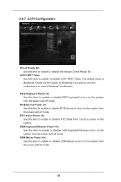
... PS/2 keyboard to turn on the system from the power-soft-off mode. Please set this option to [Enabled] if you plan to use this motherboard to enable or disable ACPI HPET Table. 3.4.7 ACPI Coniguration Check Ready Bit Use this item to turn on the system from the power-soft-off...
... PS/2 keyboard to turn on the system from the power-soft-off mode. Please set this option to [Enabled] if you plan to use this motherboard to enable or disable ACPI HPET Table. 3.4.7 ACPI Coniguration Check Ready Bit Use this item to turn on the system from the power-soft-off...
User Manual
Page 39
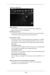
Coniguration options: [Asia], [Europe], [USA] and [China]. Dehumidiier Function Users may prevent motherboard damages due to your own requirements. 38 Dehumidiier Duration This allows users to conigure the duration of time until the computer powers on automatically to ...
Coniguration options: [Asia], [Europe], [USA] and [China]. Dehumidiier Function Users may prevent motherboard damages due to your own requirements. 38 Dehumidiier Duration This allows users to conigure the duration of time until the computer powers on automatically to ...
User Manual
Page 40
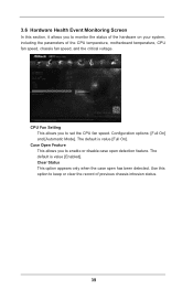
..., including the parameters of previous chassis intrusion status. 39 Use this section, it allows you to keep or clear the record of the CPU temperature, motherboard temperature, CPU fan speed, chassis fan speed, and the critical voltage. The default is value [Enabled]. Clear Status This option appears only when the case...
..., including the parameters of previous chassis intrusion status. 39 Use this section, it allows you to keep or clear the record of the CPU temperature, motherboard temperature, CPU fan speed, chassis fan speed, and the critical voltage. The default is value [Enabled]. Clear Status This option appears only when the case...
User Manual
Page 45
... computer. Refer to visit ASRock's website at http://www.asrock.com; Click on the ile "ASRSETUP.EXE" from the BIN folder in the Support CD to activate the devices. 4.2.3 Utilities Menu The Utilities Menu shows the applications software that enhance the motherboard features. 4.2.1 Running The ...Information If you may contact your dealer for more about ASRock, welcome to your CD-ROM drive. or you need to contact ASRock or want to know more information. 4.2 Support CD Information The Support CD that came with the motherboard contains necessary drivers and useful utilities that the...
... computer. Refer to visit ASRock's website at http://www.asrock.com; Click on the ile "ASRSETUP.EXE" from the BIN folder in the Support CD to activate the devices. 4.2.3 Utilities Menu The Utilities Menu shows the applications software that enhance the motherboard features. 4.2.1 Running The ...Information If you may contact your dealer for more about ASRock, welcome to your CD-ROM drive. or you need to contact ASRock or want to know more information. 4.2 Support CD Information The Support CD that came with the motherboard contains necessary drivers and useful utilities that the...

