
User Manual
Page 3
Contents 1 Introduction 5 1.1 Package Contents 5 1.2 Specifications 6 1.3 Motherboard Layout (H61M-VGS R2.0 / H61M-VS R2.0 11 1.4 I/O Panel (H61M-VGS R2.0 12 1.5 I/O Panel (H61M-VS R2.0 13 2 Installation 14 2.1 Screw Holes 14 2.2 Pre-installation Precautions 14 2.3 CPU Installation 15 2.4 Installation of Heatsink and CPU fan 17 2.5 Installation of Memory Modules (DIMM 18 2.6 Expansion Slots (PCI Express Slots 19 2.7 Multi Monitor Feature 20 2.8 Jumpers Setup...
Contents 1 Introduction 5 1.1 Package Contents 5 1.2 Specifications 6 1.3 Motherboard Layout (H61M-VGS R2.0 / H61M-VS R2.0 11 1.4 I/O Panel (H61M-VGS R2.0 12 1.5 I/O Panel (H61M-VS R2.0 13 2 Installation 14 2.1 Screw Holes 14 2.2 Pre-installation Precautions 14 2.3 CPU Installation 15 2.4 Installation of Heatsink and CPU fan 17 2.5 Installation of Memory Modules (DIMM 18 2.6 Expansion Slots (PCI Express Slots 19 2.7 Multi Monitor Feature 20 2.8 Jumpers Setup...
User Manual
Page 4
3 UEFI SETUP UTILITY 32 3.1 Introduction 32 3.1.1 UEFI Menu Bar 32 3.1.2 Navigation Keys 33 3.2 Main Screen 33 3.3 OC Tweaker Screen 35 3.4 Advanced Screen 38 3.4.1 CPU Configuration 39 3.4.2 North Bridge Configuration 41 3.4.3 South Bridge Configuration 43 3.4.4 Storage Configuration 44 3.4.5 Super IO Confi...
3 UEFI SETUP UTILITY 32 3.1 Introduction 32 3.1.1 UEFI Menu Bar 32 3.1.2 Navigation Keys 33 3.2 Main Screen 33 3.3 OC Tweaker Screen 35 3.4 Advanced Screen 38 3.4.1 CPU Configuration 39 3.4.2 North Bridge Configuration 41 3.4.3 South Bridge Configuration 43 3.4.4 Storage Configuration 44 3.4.5 Super IO Confi...

User Manual
Page 5
... VGA cards and CPU support lists on ASRock website without notice. It delivers excellent performance with robust design conforming to ASRock's commitment to BIOS setup and information of this motherboard, please visit our website for details. 5 ASRock website http://www.asrock.com If you for purchasing ASRock H61M-VGS R2.0 / H61M-VS R2.0 motherboard, a reliable motherboard produced under ASRock's consistently stringent quality...
... VGA cards and CPU support lists on ASRock website without notice. It delivers excellent performance with robust design conforming to ASRock's commitment to BIOS setup and information of this motherboard, please visit our website for details. 5 ASRock website http://www.asrock.com If you for purchasing ASRock H61M-VGS R2.0 / H61M-VS R2.0 motherboard, a reliable motherboard produced under ASRock's consistently stringent quality...
User Manual
Page 6
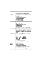
... 1) - resolution up to -Use USB 2.0 Ports - 1 x RJ-45 LAN Port with LED (ACT/LINK LED and SPEED LED) 6 Solid Capacitor for CPU power - Supports D-Sub with Intel® Sandy Bridge CPU - H61M-VS R2.0 Realtek PCIE x1 LAN RTL8105E, speed 10/100 Mb/s - Supports Hyper-Threading Technology (see CAUTION 4) - Max. Max. Dual Channel DDR3 Memory...
... 1) - resolution up to -Use USB 2.0 Ports - 1 x RJ-45 LAN Port with LED (ACT/LINK LED and SPEED LED) 6 Solid Capacitor for CPU power - Supports D-Sub with Intel® Sandy Bridge CPU - H61M-VS R2.0 Realtek PCIE x1 LAN RTL8105E, speed 10/100 Mb/s - Supports Hyper-Threading Technology (see CAUTION 4) - Max. Max. Dual Channel DDR3 Memory...
User Manual
Page 7
... 2.0 ports) - 32Mb AMI BIOS - Creative Sound Blaster X-Fi MB - ASRock APP Charger (see CAUTION 8) - ASRock SmartView (see CAUTION 7) - Boot Failure Guard (B.F.G.) - CPU/Chassis Quiet Fan (Allow Chassis Fan Speed Auto-Adjust by CPU Temperature) - HD Audio Jack: Line in/Front Speaker/Microphone - 4 x ...header - AMI UEFI Legal BIOS with GUI support - IGPU, DRAM, PCH, CPU PLL, VTT, VCCSA Voltage Multi-adjustment - ASRock Instant Flash (see CAUTION 9) - ASRock XFast USB (see CAUTION 6) - Good Night LED - CPU/Chassis Fan Multi-Speed Control - Supports "Plug and Play" - ACPI 1.1...
... 2.0 ports) - 32Mb AMI BIOS - Creative Sound Blaster X-Fi MB - ASRock APP Charger (see CAUTION 8) - ASRock SmartView (see CAUTION 7) - Boot Failure Guard (B.F.G.) - CPU/Chassis Quiet Fan (Allow Chassis Fan Speed Auto-Adjust by CPU Temperature) - HD Audio Jack: Line in/Front Speaker/Microphone - 4 x ...header - AMI UEFI Legal BIOS with GUI support - IGPU, DRAM, PCH, CPU PLL, VTT, VCCSA Voltage Multi-adjustment - ASRock Instant Flash (see CAUTION 9) - ASRock XFast USB (see CAUTION 6) - Good Night LED - CPU/Chassis Fan Multi-Speed Control - Supports "Plug and Play" - ACPI 1.1...

User Manual
Page 8
.... The maximum shared memory size is defined by overclocking. ASRock website: http://www.asrock.com 8 Your friends then can save your OC settings as a profile and share with 64-bit CPU, there is a certain risk involved with overclocking, including adjusting the ...EuP Ready (ErP/EuP ready power supply is required) (see CAUTION 13) * For detailed product information, please visit our website: http://www.asrock.com WARNING Please realize that there is no such limitation. 4. We are allowed to change. CAUTION! 1. This motherboard supports Dual Channel Memory ...
.... The maximum shared memory size is defined by overclocking. ASRock website: http://www.asrock.com 8 Your friends then can save your OC settings as a profile and share with 64-bit CPU, there is a certain risk involved with overclocking, including adjusting the ...EuP Ready (ErP/EuP ready power supply is required) (see CAUTION 13) * For detailed product information, please visit our website: http://www.asrock.com WARNING Please realize that there is no such limitation. 4. We are allowed to change. CAUTION! 1. This motherboard supports Dual Channel Memory ...
User Manual
Page 9
... USB can watch Youtube HD video and download files simultaneously. ASRock XFast LAN provides a faster internet access, which data streams you keep in a few clicks without entering operating systems first like MS-DOS or Windows®. While CPU overheat is IE8. To use FAT32/16/12 file system.... file to your computer and up to RAM (S3), hibernation mode (S4) or power off (S5). ASRock APP Charger allows you resume the system, please check if the CPU fan on the property of Your Data: With the status window, you can press key during the POST or press...
... USB can watch Youtube HD video and download files simultaneously. ASRock XFast LAN provides a faster internet access, which data streams you keep in a few clicks without entering operating systems first like MS-DOS or Windows®. While CPU overheat is IE8. To use FAT32/16/12 file system.... file to your computer and up to RAM (S3), hibernation mode (S4) or power off (S5). ASRock APP Charger allows you resume the system, please check if the CPU fan on the property of Your Data: With the status window, you can press key during the POST or press...
User Manual
Page 10
... can be under 100 mA current consumption. EuP, stands for Energy Using Product, was a provision regulated by European Union to adopt three different CPU cooler types, Socket LGA 775, LGA 1155 and LGA 1156. 12. According to Intel's suggestion, the EuP ready power supply must meet EuP standard, an ...
... can be under 100 mA current consumption. EuP, stands for Energy Using Product, was a provision regulated by European Union to adopt three different CPU cooler types, Socket LGA 775, LGA 1155 and LGA 1156. 12. According to Intel's suggestion, the EuP ready power supply must meet EuP standard, an ...

User Manual
Page 11
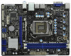
1.3 Motherboard Layout (H61M-VGS R2.0 / H61M-VS R2.0) 1 17.3cm (6.8 in) 23 PS2 Mouse PS2 Keyboard CPU_FAN1 ATX12V1 RoHS VGA1 AT X P W R 1 22.6cm (8.9 in) DDR3_B1 (64 bit, 240-pin module) DDR3_A1 (64 bit, ... 1 CHA_FAN1 8 COM1 USB6_7 PLED PWRBTN 1 1 1 HDLED RESET PANEL1 SATA2_2 SATA2_0 19 18 17 16 15 14 13 12 11 10 9 1 1155-Pin CPU Socket 2 ATX 12V Power Connector (ATX12V1) 3 CPU Fan Connector (CPU_FAN1) 4 ATX Power Connector (ATXPWR1) 5 2 x 240-pin DDR3 DIMM Slots (Dual Channel: DDR3_A1, DDR3_B1, Blue) 6 Intel H61 Chipset 7 32Mb SPI...
1.3 Motherboard Layout (H61M-VGS R2.0 / H61M-VS R2.0) 1 17.3cm (6.8 in) 23 PS2 Mouse PS2 Keyboard CPU_FAN1 ATX12V1 RoHS VGA1 AT X P W R 1 22.6cm (8.9 in) DDR3_B1 (64 bit, 240-pin module) DDR3_A1 (64 bit, ... 1 CHA_FAN1 8 COM1 USB6_7 PLED PWRBTN 1 1 1 HDLED RESET PANEL1 SATA2_2 SATA2_0 19 18 17 16 15 14 13 12 11 10 9 1 1155-Pin CPU Socket 2 ATX 12V Power Connector (ATX12V1) 3 CPU Fan Connector (CPU_FAN1) 4 ATX Power Connector (ATXPWR1) 5 2 x 240-pin DDR3 DIMM Slots (Dual Channel: DDR3_A1, DDR3_B1, Blue) 6 Intel H61 Chipset 7 32Mb SPI...
User Manual
Page 15
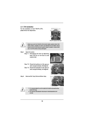
... (Pick and Place Cap). 1. Do not force to fully open position at approximately 100 degrees. Step 1. Open the socket: Step 1-1. Otherwise, the CPU will be placed if returning the motherboard for after service. 15 Load Plate Load Lever Contact Array Socket Body 1155-Pin Socket Overview Before you... insert the 1155-Pin CPU into the socket if above situation is recommended to use the cap tab to clear retention tab. It is found. Step 1-2. This...
... (Pick and Place Cap). 1. Do not force to fully open position at approximately 100 degrees. Step 1. Open the socket: Step 1-1. Otherwise, the CPU will be placed if returning the motherboard for after service. 15 Load Plate Load Lever Contact Array Socket Body 1155-Pin Socket Overview Before you... insert the 1155-Pin CPU into the socket if above situation is recommended to use the cap tab to clear retention tab. It is found. Step 1-2. This...
User Manual
Page 16
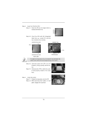
... key 1155-Pin Socket For proper inserting, please ensure to the orient keys. Step 3-4. Carefully place the CPU into the socket by the edge where is within the socket and properly mated to match the two orientation key notches of the socket. Locate ...Pin1 and the two orientation key notches. Step 3-3. Step 4-2. Step 4. While pressing down lightly on load plate, engage the load lever. 16 Orient the CPU with the two alignment keys of the CPU with IHS (Integrated Heat Sink) up. Rotate the load plate onto the IHS. black line Step 3-2. Hold the...
... key 1155-Pin Socket For proper inserting, please ensure to the orient keys. Step 3-4. Carefully place the CPU into the socket by the edge where is within the socket and properly mated to match the two orientation key notches of the socket. Locate ...Pin1 and the two orientation key notches. Step 3-3. Step 4-2. Step 4. While pressing down lightly on load plate, engage the load lever. 16 Orient the CPU with the two alignment keys of the CPU with IHS (Integrated Heat Sink) up. Rotate the load plate onto the IHS. black line Step 3-2. Hold the...

User Manual
Page 17
...1156. Connect fan header with fan operation or contact other . Secure excess cable with tie-wrap to ensure cable does not interfere with the CPU fan connector on the motherboard. Please be secured on the motherboard. Fan cables on the motherboard (CPU_ FAN1, see page 11, No. ...side closest to MB header Fastener slots pointing straight out Press Down (4 Places) If you need to spray thermal interface material between the CPU and the heatsink to improve heat dissipation. For proper installation, please kindly refer to illustrate the installation of the heatsink for Socket LGA...
...1156. Connect fan header with fan operation or contact other . Secure excess cable with tie-wrap to ensure cable does not interfere with the CPU fan connector on the motherboard. Please be secured on the motherboard. Fan cables on the motherboard (CPU_ FAN1, see page 11, No. ...side closest to MB header Fastener slots pointing straight out Press Down (4 Places) If you need to spray thermal interface material between the CPU and the heatsink to improve heat dissipation. For proper installation, please kindly refer to illustrate the installation of the heatsink for Socket LGA...

User Manual
Page 25
... FAN_SPEED_CONTROL (3-pin PWR_FAN1) (see p.11 No. 3) 4 3 2 1 GND +12V CPU_FAN_SPEED FAN_SPEED_CONTROL Please connect the CPU fan cable to the connector and match the black wire to the ground pin. CPU Fan Connectors (4-pin CPU_FAN1) (see p.11 No. 23) Please connect the fan cables to the fan connectors and... provides 24-pin ATX power connector, 12 24 it to this connector. 1 13 Though this motherboard provides 4-Pin CPU fan (Quiet Fan) support, the 3-Pin CPU fan still can still work successfully even without the fan speed control function. A front panel module mainly consists of ...
... FAN_SPEED_CONTROL (3-pin PWR_FAN1) (see p.11 No. 3) 4 3 2 1 GND +12V CPU_FAN_SPEED FAN_SPEED_CONTROL Please connect the CPU fan cable to the connector and match the black wire to the ground pin. CPU Fan Connectors (4-pin CPU_FAN1) (see p.11 No. 23) Please connect the fan cables to the fan connectors and... provides 24-pin ATX power connector, 12 24 it to this connector. 1 13 Though this motherboard provides 4-Pin CPU fan (Quiet Fan) support, the 3-Pin CPU fan still can still work successfully even without the fan speed control function. A front panel module mainly consists of ...

User Manual
Page 35
...and voltage points to run faster than marked frequency in specific condition. Load GPU EZ OC Setting Use this item to [Enabled]. CPU Ratio Setting Use this item to change the ratio value of this item to enable or disable Intel Turbo Boost Technology. Please note that ...overclocking may reduce CPU voltage and lead to system stability or compatibility issue with some power supplies. The default value is Intel's new power saving technology. Intel ...
...and voltage points to run faster than marked frequency in specific condition. Load GPU EZ OC Setting Use this item to [Enabled]. CPU Ratio Setting Use this item to change the ratio value of this item to enable or disable Intel Turbo Boost Technology. Please note that ...overclocking may reduce CPU voltage and lead to system stability or compatibility issue with some power supplies. The default value is Intel's new power saving technology. Intel ...

User Manual
Page 36
...) Use this item to change Command Rate (CR) Auto/Manual setting. The default is [Auto]. Core Current Limit Use this item to add voltage when CPU is in Turbo mode. Row Precharge Time (tRP) Use this item to change Write Recovery Time (tWR) Auto/Manual setting. Write Recovery Time (tWR) Use...
...) Use this item to change Command Rate (CR) Auto/Manual setting. The default is [Auto]. Core Current Limit Use this item to add voltage when CPU is in Turbo mode. Row Precharge Time (tRP) Use this item to change Write Recovery Time (tWR) Auto/Manual setting. Write Recovery Time (tWR) Use...

User Manual
Page 37
... value is [Auto]. ODT WR (CHB) Use this option, you are allowed to load and save three user defaults according to your own requirements. 37 CPU Core Voltage Use this to select PCH Voltage. The default value is [Auto]. PCH Voltage Use this to select... CPU Core Voltage. CPU PLL Voltage Use this to select VCCSA Voltage. The default value is [Auto]. VCCSA Voltage Use this to select CPU PLL Voltage. The default is [Auto]. Voltage Control Power Saving Mode Use this item...
... value is [Auto]. ODT WR (CHB) Use this option, you are allowed to load and save three user defaults according to your own requirements. 37 CPU Core Voltage Use this to select PCH Voltage. The default value is [Auto]. PCH Voltage Use this to select... CPU Core Voltage. CPU PLL Voltage Use this to select VCCSA Voltage. The default value is [Auto]. VCCSA Voltage Use this to select CPU PLL Voltage. The default is [Auto]. Voltage Control Power Saving Mode Use this item...

User Manual
Page 38
...USB flash drive, floppy disk or hard drive, then you execute ASRock Instant Flash utility, the utility will show the UEFI files and their respective information. ASRock Instant Flash ASRock Instant Flash is a UEFI flash utility embedded in a few clicks without entering ...operating systems first like MS-DOS or Windows®. If you can update your UEFI only in Flash ROM. Just launch this section may set the configurations for the following items: CPU...
...USB flash drive, floppy disk or hard drive, then you execute ASRock Instant Flash utility, the utility will show the UEFI files and their respective information. ASRock Instant Flash ASRock Instant Flash is a UEFI flash utility embedded in a few clicks without entering ...operating systems first like MS-DOS or Windows®. If you can update your UEFI only in Flash ROM. Just launch this section may set the configurations for the following items: CPU...
User Manual
Page 39
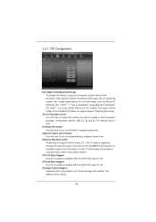
...State package limit register. Configuration options: [All], [1], [2] and [3]. The C1 state is [Auto]. 39 CPU C3 State Support Use this to enable or disable CPU C6 (ACPI C3) report to OS. The default value is supported through the native processor instructions HLT and MWAIT and requires... power state, the processor maintains the context of the system caches. Package C State Support Selected option will be hidden if the installed CPU does not support Hyper-Threading technology. The default value is [All]. Adjacent Cache Line Prefetch Use this item to turn on /off ...
...State package limit register. Configuration options: [All], [1], [2] and [3]. The C1 state is [Auto]. 39 CPU C3 State Support Use this to enable or disable CPU C6 (ACPI C3) report to OS. The default value is supported through the native processor instructions HLT and MWAIT and requires... power state, the processor maintains the context of the system caches. Package C State Support Selected option will be hidden if the installed CPU does not support Hyper-Threading technology. The default value is [All]. Adjacent Cache Line Prefetch Use this item to turn on /off ...

User Manual
Page 40
...by Vanderpool Technology. No-Excute Memory Protection No-Execution (NX) Memory Protection Technology is [Disabled]. Please be hidden if the installed CPU does not support Intel Virtualization Technology. Intel Virtualization Technology When this option is set to [Enabled], a VMM (Virtual Machine Architecture...) can prevent data pages from overheated. This option will be hidden if the current CPU does not support No-Excute Memory Protection. An IA-32 processor with "No Execute (NX) Memory Protection" can utilize the additional ...
...by Vanderpool Technology. No-Excute Memory Protection No-Execution (NX) Memory Protection Technology is [Disabled]. Please be hidden if the installed CPU does not support Intel Virtualization Technology. Intel Virtualization Technology When this option is set to [Enabled], a VMM (Virtual Machine Architecture...) can prevent data pages from overheated. This option will be hidden if the current CPU does not support No-Excute Memory Protection. An IA-32 processor with "No Execute (NX) Memory Protection" can utilize the additional ...

User Manual
Page 48
... Setting This allows you to monitor the status of the hardware on your system, including the parameters of the CPU temperature, motherboard temperature, CPU fan speed, chassis fan speed, and the critical voltage. Chassis Fan Setting This allows you to set the chassis fan speed. The default value is ...
... Setting This allows you to monitor the status of the hardware on your system, including the parameters of the CPU temperature, motherboard temperature, CPU fan speed, chassis fan speed, and the critical voltage. Chassis Fan Setting This allows you to set the chassis fan speed. The default value is ...


