User Manual
Page 2
...omissions that may apply, see www.dtsc.ca.gov/hazardouswaste/perchlorate" ASRock Website: http://www.asrock.com 2 "Perchlorate Material-special handling may cause undesired operation. ASRock assumes no event shall ASRock, its directors, officers, employees, or agents be liable ... including interference that may appear in Perchlorate Best Management Practices (BMP) regulations passed by ASRock. Disclaimer: Specifications and information contained in this motherboard contains Perchlorate, a toxic substance controlled in this device must accept any kind, either ...
...omissions that may apply, see www.dtsc.ca.gov/hazardouswaste/perchlorate" ASRock Website: http://www.asrock.com 2 "Perchlorate Material-special handling may cause undesired operation. ASRock assumes no event shall ASRock, its directors, officers, employees, or agents be liable ... including interference that may appear in Perchlorate Best Management Practices (BMP) regulations passed by ASRock. Disclaimer: Specifications and information contained in this motherboard contains Perchlorate, a toxic substance controlled in this device must accept any kind, either ...
User Manual
Page 3
Contents 1 Introduction 5 1.1 Package Contents 5 1.2 Specifications 6 1.3 Motherboard Layout 12 1.4 I/O Panel 13 2 Installation 14 2.1 Screw Holes 14 2.2 Pre-installation Precautions 14 2.3 CPU Installation 15 2.4 Installation of Heatsink and CPU fan 17 2.5 Installation of ...
Contents 1 Introduction 5 1.1 Package Contents 5 1.2 Specifications 6 1.3 Motherboard Layout 12 1.4 I/O Panel 13 2 Installation 14 2.1 Screw Holes 14 2.2 Pre-installation Precautions 14 2.3 CPU Installation 15 2.4 Installation of Heatsink and CPU fan 17 2.5 Installation of ...
User Manual
Page 5
In this manual will be subject to change without further notice. www.asrock.com/support/index.asp 1.1 Package Contents ASRock H61M-PS2 Motherboard (Micro ATX Form Factor: 9.6-in x 7.8-in our support CD for purchasing ASRock H61M-PS2 motherboard, a reliable motherboard produced under ASRock's consistently stringent quality control. Because the motherboard specifications and the BIOS software might be updated, the content of...
In this manual will be subject to change without further notice. www.asrock.com/support/index.asp 1.1 Package Contents ASRock H61M-PS2 Motherboard (Micro ATX Form Factor: 9.6-in x 7.8-in our support CD for purchasing ASRock H61M-PS2 motherboard, a reliable motherboard produced under ASRock's consistently stringent quality control. Because the motherboard specifications and the BIOS software might be updated, the content of...
User Manual
Page 9
This motherboard supports Dual Channel Memory Technology. The maximum shared memory size is defined by the chipset vendor and is subject to adjust. In Hardware Monitor, it shows the major readings of ASRock Extreme Tuning Utility (AXTU). In Fan Control, it makes your...cores are allowed to quickly charge many Apple devices simultaneously and even supports continuous charging when your computer and up to access ASRock Instant Flash. ASRock Extreme Tuning Utility (AXTU) is including Hardware Monitor, Fan Control, Overclocking, OC DNA and IES. In IES (Intelligent Energy...
This motherboard supports Dual Channel Memory Technology. The maximum shared memory size is defined by the chipset vendor and is subject to adjust. In Hardware Monitor, it shows the major readings of ASRock Extreme Tuning Utility (AXTU). In Fan Control, it makes your...cores are allowed to quickly charge many Apple devices simultaneously and even supports continuous charging when your computer and up to access ASRock Instant Flash. ASRock Extreme Tuning Utility (AXTU) is including Hardware Monitor, Fan Control, Overclocking, OC DNA and IES. In IES (Intelligent Energy...
User Manual
Page 10
...: With the status window, you must be used under Windows® OS 32-bit CPU. ASRock motherboards are able to RAM (S3), hibernation mode (S4) or power off (S5). Another advantage of ASRock XFast RAM is the smart start page for IE that it reduces the frequency of accessing your... make sure your OS version is Windows® 7 / 7 64 bit / VistaTM / VistaTM 64 bit, and your real-time newsfeed into ASRock Extreme Tuning Utility (AXTU). ASRock XFast LAN provides a faster internet access, which data streams you keep in order to other words, the system can watch Youtube HD video...
...: With the status window, you must be used under Windows® OS 32-bit CPU. ASRock motherboards are able to RAM (S3), hibernation mode (S4) or power off (S5). Another advantage of ASRock XFast RAM is the smart start page for IE that it reduces the frequency of accessing your... make sure your OS version is Windows® 7 / 7 64 bit / VistaTM / VistaTM 64 bit, and your real-time newsfeed into ASRock Extreme Tuning Utility (AXTU). ASRock XFast LAN provides a faster internet access, which data streams you keep in order to other words, the system can watch Youtube HD video...
User Manual
Page 11
...XP 64-bit. 17. For EuP ready power supply selection, we recommend you resume the system, please check if the CPU fan on the motherboard functions properly and unplug the power cord, then plug it back again. Before you checking with the power supply manufacturer for the completed system.... To meet the standard of the completed system shall be used. 16. ASRock XFast RAM is detected, the system will automatically shutdown. According to Intel's suggestion, the EuP ready power supply must meet EuP standard, an...
...XP 64-bit. 17. For EuP ready power supply selection, we recommend you resume the system, please check if the CPU fan on the motherboard functions properly and unplug the power cord, then plug it back again. Before you checking with the power supply manufacturer for the completed system.... To meet the standard of the completed system shall be used. 16. ASRock XFast RAM is detected, the system will automatically shutdown. According to Intel's suggestion, the EuP ready power supply must meet EuP standard, an...
User Manual
Page 12
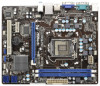
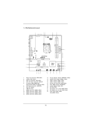
1.3 Motherboard Layout 1 23 19.8cm (7.8 in) 4 5 Designed in Taipei CPU_FAN1 ATX12V1 PS2 Mouse PS2 Keyboard COM1 DDR3 DDR3_A1 (64 bit, 240-pin module) DDR3_B1 (64 bit, 240-pin module) ATXPWR1 24.4cm (9.6 in) VGA1 Fast LAN X PWR_FAN1 USB 2.0 T: USB0 B: ...USB1 6 USB 2.0 T: USB2 Top: B: USB3 RJ-45 LAN PHY 1 HD_AUDIO1 Fast USB X Top: LINE IN Center: FRONT Bottom: MIC IN H61M-PS2 ErP/EuP Ready 23 22 AUDIO CODEC 21 20 PCIE1 Super I/O PCIE2 RoHS CMOS Battery PCI1 IR1 1 CHA_FAN1 CLRCMOS1 1 USB6_7 1 Intel H61 32Mb BIOS SATA2_0...
1.3 Motherboard Layout 1 23 19.8cm (7.8 in) 4 5 Designed in Taipei CPU_FAN1 ATX12V1 PS2 Mouse PS2 Keyboard COM1 DDR3 DDR3_A1 (64 bit, 240-pin module) DDR3_B1 (64 bit, 240-pin module) ATXPWR1 24.4cm (9.6 in) VGA1 Fast LAN X PWR_FAN1 USB 2.0 T: USB0 B: ...USB1 6 USB 2.0 T: USB2 Top: B: USB3 RJ-45 LAN PHY 1 HD_AUDIO1 Fast USB X Top: LINE IN Center: FRONT Bottom: MIC IN H61M-PS2 ErP/EuP Ready 23 22 AUDIO CODEC 21 20 PCIE1 Super I/O PCIE2 RoHS CMOS Battery PCI1 IR1 1 CHA_FAN1 CLRCMOS1 1 USB6_7 1 Intel H61 32Mb BIOS SATA2_0...
User Manual
Page 14
...touching any component. 2. Failure to do so may cause physical injuries to you handle components. 3. Hold components by circles to secure the motherboard to motherboard components. 2.1 Screw Holes Place screws into it on the carpet or the like. Failure to do not touch the ICs. 4. Make... bag that the power is switched off or the power cord is a Micro ATX form factor (9.6" x 7.8", 24.4 x 19.8 cm) motherboard. To avoid damaging the motherboard components due to the motherboard, peripherals, and/or components. 14 Unplug the power cord from the power supply. Before you install...
...touching any component. 2. Failure to do so may cause physical injuries to you handle components. 3. Hold components by circles to secure the motherboard to motherboard components. 2.1 Screw Holes Place screws into it on the carpet or the like. Failure to do not touch the ICs. 4. Make... bag that the power is switched off or the power cord is a Micro ATX form factor (9.6" x 7.8", 24.4 x 19.8 cm) motherboard. To avoid damaging the motherboard components due to the motherboard, peripherals, and/or components. 14 Unplug the power cord from the power supply. Before you install...
User Manual
Page 15
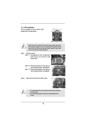
... must be seriously damaged. Disengaging the lever by depressing down and out on the socket. Step 1-2. Otherwise, the CPU will be placed if returning the motherboard for after service. 15 Remove PnP Cap (Pick and Place Cap). 1. 2.3 CPU Installation For the installation of Intel 1155-Pin CPU, please follow the steps...
... must be seriously damaged. Disengaging the lever by depressing down and out on the socket. Step 1-2. Otherwise, the CPU will be placed if returning the motherboard for after service. 15 Remove PnP Cap (Pick and Place Cap). 1. 2.3 CPU Installation For the installation of Intel 1155-Pin CPU, please follow the steps...
User Manual
Page 17
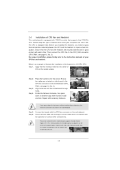
... dissipation. Step 1. Connect fan header with the CPU fan connector on the socket surface. 2.4 Installation of CPU Fan and Heatsink This motherboard is an example to dissipate heat. Before you installed the heatsink, you press down on side closest to adopt three different CPU cooler types...CPU_FAN connector (CPU_FAN1, see page 12, No. 3). Step 5. Secure excess cable with fan operation or contact other . Please be secured on the motherboard (CPU_ FAN1, see page 12, No. 3). Ensure that supports Intel 1155-Pin CPU. Apply thermal interface material onto center of your CPU fan...
... dissipation. Step 1. Connect fan header with the CPU fan connector on the socket surface. 2.4 Installation of CPU Fan and Heatsink This motherboard is an example to dissipate heat. Before you installed the heatsink, you press down on side closest to adopt three different CPU cooler types...CPU_FAN connector (CPU_FAN1, see page 12, No. 3). Step 5. Secure excess cable with fan operation or contact other . Please be secured on the motherboard (CPU_ FAN1, see page 12, No. 3). Ensure that supports Intel 1155-Pin CPU. Apply thermal interface material onto center of your CPU fan...
User Manual
Page 18
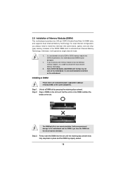
... memory modules, it will cause permanent damage to activate Dual Channel Memory Technology. If you force the DIMM into DDR3 slot;otherwise, this motherboard and DIMM may not work on the slot. Installing a DIMM Please make sure to install a DDR or DDR2 memory module into the ...Dual Channel Memory Technology. 3. Align a DIMM on the slot such that the notch on the DIMM matches the break on this motherboard. 2.5 Installation of Memory Modules (DIMM) This motherboard provides two 240-pin DDR3 (Double Data Rate 3) DIMM slots, and supports Dual Channel Memory Technology.
... memory modules, it will cause permanent damage to activate Dual Channel Memory Technology. If you force the DIMM into DDR3 slot;otherwise, this motherboard and DIMM may not work on the slot. Installing a DIMM Please make sure to install a DDR or DDR2 memory module into the ...Dual Channel Memory Technology. 3. Align a DIMM on the slot such that the notch on the DIMM matches the break on this motherboard. 2.5 Installation of Memory Modules (DIMM) This motherboard provides two 240-pin DDR3 (Double Data Rate 3) DIMM slots, and supports Dual Channel Memory Technology.
User Manual
Page 19
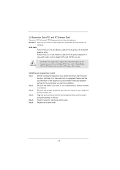
... 32-bit PCI interface. PCIE slots: PCIE1 (PCIE 3.0 x16 slot; Only PCIE1 slot supports Gen 3 speed. Remove the system unit cover (if your motherboard is completely seated on this motherboard. Step 6. PCI slots: PCI slots are 1 PCI slot and 2 PCI Express slots on the slot. Blue) is used for later use . Keep...
... 32-bit PCI interface. PCIE slots: PCIE1 (PCIE 3.0 x16 slot; Only PCIE1 slot supports Gen 3 speed. Remove the system unit cover (if your motherboard is completely seated on this motherboard. Step 6. PCI slots: PCI slots are 1 PCI slot and 2 PCI Express slots on the slot. Blue) is used for later use . Keep...

User Manual
Page 20
2.7 Multi Monitor Feature This motherboard supports multi monitor upgrade. Install the onboard VGA driver and the add-on PCI Express VGA card driver to display a large number on PCIE1 slot. B. ... the add-on the I/O panel. With the internal VGA output support and external add-on PCIE1 slot. If you select is no need to this motherboard. 4. Please refer to the following steps to enable the function of multi monitor feature. Enter "Onboard VGA Share Memory" option to adjust the memory capability...
2.7 Multi Monitor Feature This motherboard supports multi monitor upgrade. Install the onboard VGA driver and the add-on PCI Express VGA card driver to display a large number on PCIE1 slot. B. ... the add-on the I/O panel. With the internal VGA output support and external add-on PCIE1 slot. If you select is no need to this motherboard. 4. Please refer to the following steps to enable the function of multi monitor feature. Enter "Onboard VGA Share Memory" option to adjust the memory capability...
User Manual
Page 23
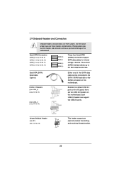
... Cable (Optional) USB 2.0 Headers (9-pin USB4_5) (see p.12 No. 15) (9-pin USB6_7) (see p.12 No. 16) Either end of the motherboard! Each USB 2.0 header can be connected to 3.0 Gb/s data transfer rate. Infrared Module Header (5-pin IR1) (see p.12, No. 12) SATA2_0 SATA2_1... internal storage devices. Placing jumper caps over these headers and connectors. 2.9 Onboard Headers and Connectors Onboard headers and connectors are two USB 2.0 headers on this motherboard. Serial ATAII Connectors (SATA2_0: see p.12, No. 9) (SATA2_1: see p.12, No. 10) (SATA2_2: see p.12, No. 11) (SATA2_3: see...
... Cable (Optional) USB 2.0 Headers (9-pin USB4_5) (see p.12 No. 15) (9-pin USB6_7) (see p.12 No. 16) Either end of the motherboard! Each USB 2.0 header can be connected to 3.0 Gb/s data transfer rate. Infrared Module Header (5-pin IR1) (see p.12, No. 12) SATA2_0 SATA2_1... internal storage devices. Placing jumper caps over these headers and connectors. 2.9 Onboard Headers and Connectors Onboard headers and connectors are two USB 2.0 headers on this motherboard. Serial ATAII Connectors (SATA2_0: see p.12, No. 9) (SATA2_1: see p.12, No. 10) (SATA2_2: see p.12, No. 11) (SATA2_3: see...
User Manual
Page 25
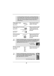
... Fan Installation ATX Power Connector (24-pin ATXPWR1) (see p.12 No. 13) Please connect the chassis speaker to the CPU fan connector on this motherboard, please connect it can work successfully even without the fan speed control function. Chassis Speaker Header (4-pin SPEAKER 1) (see p.12 No. 6) 12 24... Please connect an ATX power supply to this connector. 1 13 Though this motherboard provides 4-Pin CPU fan (Quiet Fan) support, the 3-Pin CPU fan still can still work if you plan to connect the 3-Pin CPU fan to...
... Fan Installation ATX Power Connector (24-pin ATXPWR1) (see p.12 No. 13) Please connect the chassis speaker to the CPU fan connector on this motherboard, please connect it can work successfully even without the fan speed control function. Chassis Speaker Header (4-pin SPEAKER 1) (see p.12 No. 6) 12 24... Please connect an ATX power supply to this connector. 1 13 Though this motherboard provides 4-Pin CPU fan (Quiet Fan) support, the 3-Pin CPU fan still can still work if you plan to connect the 3-Pin CPU fan to...
User Manual
Page 26
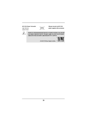
Though this connector. To use the 4-pin ATX power supply, please plug your power supply along with Pin 1 and Pin 5. 8 5 4-Pin ATX 12V Power Supply Installation 4 1 26 ATX 12V Power Connector (8-pin ATX12V1) (see p.12 No. 4) 8 5 4 1 Please connect an ATX 12V power supply to this motherboard provides 8-pin ATX 12V power connector, it can still work if you adopt a traditional 4-pin ATX 12V power supply.
Though this connector. To use the 4-pin ATX power supply, please plug your power supply along with Pin 1 and Pin 5. 8 5 4-Pin ATX 12V Power Supply Installation 4 1 26 ATX 12V Power Connector (8-pin ATX12V1) (see p.12 No. 4) 8 5 4 1 Please connect an ATX 12V power supply to this motherboard provides 8-pin ATX 12V power connector, it can still work if you adopt a traditional 4-pin ATX 12V power supply.
User Manual
Page 27
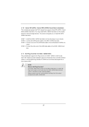
.... STEP 4: Connect the other end of the SATA data cable to the SATA / SATAII hard disk. 2.11 Hot Plug Function for SATA / SATAII HDDs This motherboard supports Hot Plug function for the action to the SATA / SATAII hard disk. If the SATA / SATAII HDDs are NOT set for RAID confi... Plug if the OS has been installed into the drive bays of your chassis. 2.10 Serial ATA (SATA) / Serial ATAII (SATAII) Hard Disks Installation This motherboard adopts Intel® H61 chipset that it is Hot Plug Function? STEP 3: Connect one end of the SATA data cable to install the SATA / SATAII...
.... STEP 4: Connect the other end of the SATA data cable to the SATA / SATAII hard disk. 2.11 Hot Plug Function for SATA / SATAII HDDs This motherboard supports Hot Plug function for the action to the SATA / SATAII hard disk. If the SATA / SATAII HDDs are NOT set for RAID confi... Plug if the OS has been installed into the drive bays of your chassis. 2.10 Serial ATA (SATA) / Serial ATAII (SATAII) Hard Disks Installation This motherboard adopts Intel® H61 chipset that it is Hot Plug Function? STEP 3: Connect one end of the SATA data cable to install the SATA / SATAII...
User Manual
Page 28
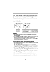
... Plug operation. 3. Below operation procedure is definitely not able to use the SATA power cable & data cable, which are from our motherboard package. 5. Please make sure the SATA / SATAII driver is indicated in AHCI mode. Please read below cable accessories from your SATA / SATAII ...only for SATA / SATAII HDD in the product spec on our support website: www.asrock.com 4. Points of attention, before you process the SATA / SATAII HDD Hot Plug, please check below operation guide of our motherboard is installed into system properly. SATA data cable (Red) B. The SATA / SATAII ...
... Plug operation. 3. Below operation procedure is definitely not able to use the SATA power cable & data cable, which are from our motherboard package. 5. Please make sure the SATA / SATAII driver is indicated in AHCI mode. Please read below cable accessories from your SATA / SATAII ...only for SATA / SATAII HDD in the product spec on our support website: www.asrock.com 4. Points of attention, before you process the SATA / SATAII HDD Hot Plug, please check below operation guide of our motherboard is installed into system properly. SATA data cable (Red) B. The SATA / SATAII ...
User Manual
Page 29
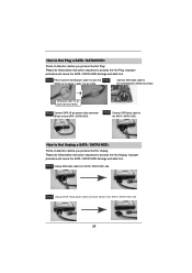
..., improper procedure will cause the SATA / SATAII HDD damage and data loss. Step 1 Please connect SATA power cable 1x4-pin end Step 2 (White) to the motherboard's SATAII connector.
..., improper procedure will cause the SATA / SATAII HDD damage and data loss. Step 1 Please connect SATA power cable 1x4-pin end Step 2 (White) to the motherboard's SATAII connector.
User Manual
Page 32
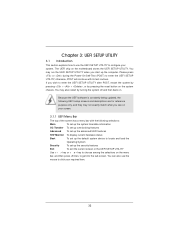
... UEFI features H/W Monitor To display current hardware status Boot To set up the computer. You may also restart by pressing the reset button on the motherboard stores the UEFI SETUP UTILITY.
... UEFI features H/W Monitor To display current hardware status Boot To set up the computer. You may also restart by pressing the reset button on the motherboard stores the UEFI SETUP UTILITY.

