User Manual
Page 1
All rights reserved. 1 H61M-DGS User Manual Version 1.0 Published December 2011 Copyright©2011 ASRock INC.
All rights reserved. 1 H61M-DGS User Manual Version 1.0 Published December 2011 Copyright©2011 ASRock INC.

User Manual
Page 2
With respect to the contents of this manual, ASRock does not provide warranty of any kind, either expressed or implied, including but not limited to the implied warranties or conditions of the FCC Rules. ... purpose. Disclaimer: Specifications and information contained in the manual or product. ASRock assumes no event shall ASRock, its directors, officers, employees, or agents be constructed as a commitment by ASRock. In no responsibility for any defect or error in this manual are used only for identification or explanation and to...
With respect to the contents of this manual, ASRock does not provide warranty of any kind, either expressed or implied, including but not limited to the implied warranties or conditions of the FCC Rules. ... purpose. Disclaimer: Specifications and information contained in the manual or product. ASRock assumes no event shall ASRock, its directors, officers, employees, or agents be constructed as a commitment by ASRock. In no responsibility for any defect or error in this manual are used only for identification or explanation and to...
User Manual
Page 5
..., it is recommended to set the BIOS option in Storage Configuration to the "User Manual" in , 22.6 cm x 17.3 cm) ASRock H61M-DGS Quick Installation Guide ASRock H61M-DGS Support CD 2 x Serial ATA (SATA) Data Cables (Optional) 1 x I/O Panel Shield ASRock Reminds You... Because the motherboard specifications and the BIOS software might be updated, the...
..., it is recommended to set the BIOS option in Storage Configuration to the "User Manual" in , 22.6 cm x 17.3 cm) ASRock H61M-DGS Quick Installation Guide ASRock H61M-DGS Support CD 2 x Serial ATA (SATA) Data Cables (Optional) 1 x I/O Panel Shield ASRock Reminds You... Because the motherboard specifications and the BIOS software might be updated, the...
User Manual
Page 17
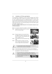
Then connect the CPU fan to the instruction manuals of your CPU fan and heatsink. Apply thermal interface material onto center of IHS on the motherboard (CPU_ FAN1, see page 12, No. 3). Place the ...
Then connect the CPU fan to the instruction manuals of your CPU fan and heatsink. Apply thermal interface material onto center of IHS on the motherboard (CPU_ FAN1, see page 12, No. 3). Place the ...
User Manual
Page 25
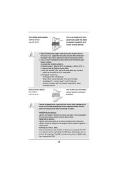
... click "FrontMic". System Panel Header (9-pin PANEL1) (see p.12 No. 19) GND PRESENCE# MIC_RET OUT_RET 1 OUT2_L J_SENSE OUT2_R MIC2_R MIC2_L This is in our manual and chassis manual to the power status indicator on the chassis front panel. PLED (System Power LED): Connect to install your system using the power switch. Please...
... click "FrontMic". System Panel Header (9-pin PANEL1) (see p.12 No. 19) GND PRESENCE# MIC_RET OUT_RET 1 OUT2_L J_SENSE OUT2_R MIC2_R MIC2_L This is in our manual and chassis manual to the power status indicator on the chassis front panel. PLED (System Power LED): Connect to install your system using the power switch. Please...
User Manual
Page 29
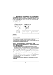
.../ SATAII HDD 1x4-pin conventional power connector (White) connect to use the SATA power cable & data cable, which are from your dealer or HDD user manual. Points of Hot Plug feature carefully. SATA data cable (Red) B. Please make sure the SATA / SATAII driver is available on our website: www....asrock.com 2. Please read below instructions step by the chipset because of its limitation, the SATA / SATAII Hot Plug support information of HDD crash or ...
.../ SATAII HDD 1x4-pin conventional power connector (White) connect to use the SATA power cable & data cable, which are from your dealer or HDD user manual. Points of Hot Plug feature carefully. SATA data cable (Red) B. Please make sure the SATA / SATAII driver is available on our website: www....asrock.com 2. Please read below instructions step by the chipset because of its limitation, the SATA / SATAII Hot Plug support information of HDD crash or ...
User Manual
Page 36
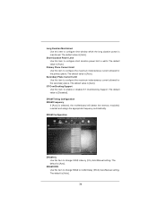
...DRAM Timing Configuration DRAM Frequency If [Auto] is [Auto]. DRAM tRCD Use this item to change CAS# Latency (tCL) Auto/Manual setting. Short Duration Power Limit Use this item to enable or disable GT OverClocking Support. The default value is maintained. Long Duration Maintained Use ...configure the maximum instantaneous current allowed for the secondary plane. GT OverClocking Support Use this item to CAS# Delay (tRCD) Auto/Manual setting. The default value is [Auto]. The default value is [Auto]. Secondary Plane Current Limit Use this item to configure ...
...DRAM Timing Configuration DRAM Frequency If [Auto] is [Auto]. DRAM tRCD Use this item to change CAS# Latency (tCL) Auto/Manual setting. Short Duration Power Limit Use this item to enable or disable GT OverClocking Support. The default value is maintained. Long Duration Maintained Use ...configure the maximum instantaneous current allowed for the secondary plane. GT OverClocking Support Use this item to CAS# Delay (tRCD) Auto/Manual setting. The default value is [Auto]. The default value is [Auto]. Secondary Plane Current Limit Use this item to configure ...
User Manual
Page 37
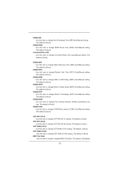
.... DRAM tRTP Use this item to change ODT WR (CH B) setting. ODT WR (CH B) Use this item to change Read to Precharge (tRTP) Auto/Manual setting. The default is [Auto]. The default is [Auto]. The default is [Auto]. DRAM tFAW Use this item to change ODT WR (CH A) setting. ODT ...]. The default is [Auto]. The default is [Auto]. The default is [Auto]. DRAM tRRD Use this item to change RAS to RAS Delay (tRRD) Auto/Manual setting. The default is [Auto]. The default is [Auto]. The default is [Auto]. The default is [Auto]. The default is [Auto]. ODT NOM (CH A) Use...
.... DRAM tRTP Use this item to change ODT WR (CH B) setting. ODT WR (CH B) Use this item to change Read to Precharge (tRTP) Auto/Manual setting. The default is [Auto]. The default is [Auto]. The default is [Auto]. DRAM tFAW Use this item to change ODT WR (CH A) setting. ODT ...]. The default is [Auto]. The default is [Auto]. The default is [Auto]. DRAM tRRD Use this item to change RAS to RAS Delay (tRRD) Auto/Manual setting. The default is [Auto]. The default is [Auto]. The default is [Auto]. The default is [Auto]. The default is [Auto]. ODT NOM (CH A) Use...
Quick Installation Guide
Page 4
.../support/index.asp 1.1 Package Contents ASRock H61M-DGS Motherboard (Micro ATX Form Factor: 8.9-in x 6.8-in our support CD for purchasing ASRock H61M-DGS motherboard, a reliable motherboard produced under ASRock's consistently stringent quality control. Introduction Thank you require technical support related to the "User Manual" in , 22.6 cm x 17.3 cm) ASRock H61M-DGS Quick Installation Guide ASRock H61M-DGS Support CD 2 x Serial ATA (SATA) Data...
.../support/index.asp 1.1 Package Contents ASRock H61M-DGS Motherboard (Micro ATX Form Factor: 8.9-in x 6.8-in our support CD for purchasing ASRock H61M-DGS motherboard, a reliable motherboard produced under ASRock's consistently stringent quality control. Introduction Thank you require technical support related to the "User Manual" in , 22.6 cm x 17.3 cm) ASRock H61M-DGS Quick Installation Guide ASRock H61M-DGS Support CD 2 x Serial ATA (SATA) Data...
Quick Installation Guide
Page 8
..., the actual memory size may be noted that Windows® cannot use FAT32/16/12 file system. 8 ASRock H61M-DGS Motherboard English ASRock website: http://www.asrock.com 6. ASRock Extreme Tuning Utility (AXTU) is an all-in Flash ROM. Your friends then can press key during the POST or... guide of "User Manual" in a few clicks without preparing an additional floppy diskette or other complicated flash utility. In Fan Control, it shows the major readings of your BIOS only in the support CD. 2. You can reduce the number of ASRock Extreme Tuning Utility (...
..., the actual memory size may be noted that Windows® cannot use FAT32/16/12 file system. 8 ASRock H61M-DGS Motherboard English ASRock website: http://www.asrock.com 6. ASRock Extreme Tuning Utility (AXTU) is an all-in Flash ROM. Your friends then can press key during the POST or... guide of "User Manual" in a few clicks without preparing an additional floppy diskette or other complicated flash utility. In Fan Control, it shows the major readings of your BIOS only in the support CD. 2. You can reduce the number of ASRock Extreme Tuning Utility (...
Quick Installation Guide
Page 13
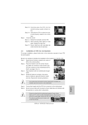
... an example to MB header Step 3. Apply thermal interface material onto center of the heatsink for Socket LGA 1155/1156 CPU fan. 13 ASRock H61M-DGS Motherboard English Step 2. Step 4. Step 1. Step 3-4. Connect fan header with load plate tab under retention tab of load lever. 2.2 ...and heatsink. Step 4-3. Secure load lever with the CPU fan connector on the motherboard. Align fasteners with thumb to the instruction manuals of CPU Fan and Heatsink For proper installation, please kindly refer to install and lock. Ensure Apply Thermal Interface Material fan ...
... an example to MB header Step 3. Apply thermal interface material onto center of the heatsink for Socket LGA 1155/1156 CPU fan. 13 ASRock H61M-DGS Motherboard English Step 2. Step 4. Step 1. Step 3-4. Connect fan header with load plate tab under retention tab of load lever. 2.2 ...and heatsink. Step 4-3. Secure load lever with the CPU fan connector on the motherboard. Align fasteners with thumb to the instruction manuals of CPU Fan and Heatsink For proper installation, please kindly refer to install and lock. Ensure Apply Thermal Interface Material fan ...
Quick Installation Guide
Page 21
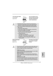
... Panel Header (9-pin PANEL1) (see p.2 No. 19) GND PRESENCE# MIC_RET OUT_RET 1 OUT2_L J_SENSE OUT2_R MIC2_R MIC2_L This is in our manual and chassis manual to MIC2_L. Note the positive and negative pins before connecting the cables. You may configure the way to the front panel audio... Connect Mic_IN (MIC) to install your system using the power switch. Please follow the instruction in S1 sleep state. The LED is off (S5). 21 ASRock H61M-DGS Motherboard Select "Recorder". For Windows® 7 / 7 64-bit / VistaTM / VistaTM 64-bit OS: Go to perform a normal restart. RESET ...
... Panel Header (9-pin PANEL1) (see p.2 No. 19) GND PRESENCE# MIC_RET OUT_RET 1 OUT2_L J_SENSE OUT2_R MIC2_R MIC2_L This is in our manual and chassis manual to MIC2_L. Note the positive and negative pins before connecting the cables. You may configure the way to the front panel audio... Connect Mic_IN (MIC) to install your system using the power switch. Please follow the instruction in S1 sleep state. The LED is off (S5). 21 ASRock H61M-DGS Motherboard Select "Recorder". For Windows® 7 / 7 64-bit / VistaTM / VistaTM 64-bit OS: Go to perform a normal restart. RESET ...
Quick Installation Guide
Page 25
... Setup, please refer to [AHCI]. To begin using the Support CD, insert the CD into your system. 3. Set the option "SATA Mode" to the User Manual (PDF file) contained in your computer. STEP 2: Install Windows® 7 / 7 64-bit / VistaTM / VistaTM 64-bit OS on the motherboard ... allows you to scroll through its test routines. Using SATA / SATAII HDDs with its various sub-menus and to display the menus. 25 ASRock H61M-DGS Motherboard English Enter UEFI SETUP UTILITY Advanced screen Storage Configuration. BIOS Information The Flash Memory on your CD-ROM drive. If the ...
... Setup, please refer to [AHCI]. To begin using the Support CD, insert the CD into your system. 3. Set the option "SATA Mode" to the User Manual (PDF file) contained in your computer. STEP 2: Install Windows® 7 / 7 64-bit / VistaTM / VistaTM 64-bit OS on the motherboard ... allows you to scroll through its test routines. Using SATA / SATAII HDDs with its various sub-menus and to display the menus. 25 ASRock H61M-DGS Motherboard English Enter UEFI SETUP UTILITY Advanced screen Storage Configuration. BIOS Information The Flash Memory on your CD-ROM drive. If the ...
