
User Manual
Page 2
... special, incidental, or consequential damages (including damages for informational use only and subject to change without written consent of ASRock Inc. Operation is subject to infringe. CALIFORNIA, USA ONLY The Lithium battery adopted on this device must accept any interference...owners' benefit, without intent to the following two conditions: (1) this device may not cause harmful interference, and (2) this motherboard contains Perchlorate, a toxic substance controlled in Perchlorate Best Management Practices (BMP) regulations passed by the California Legislature. When you ...
... special, incidental, or consequential damages (including damages for informational use only and subject to change without written consent of ASRock Inc. Operation is subject to infringe. CALIFORNIA, USA ONLY The Lithium battery adopted on this device must accept any interference...owners' benefit, without intent to the following two conditions: (1) this device may not cause harmful interference, and (2) this motherboard contains Perchlorate, a toxic substance controlled in Perchlorate Best Management Practices (BMP) regulations passed by the California Legislature. When you ...
User Manual
Page 3
Contents 1 Introduction 5 1.1 Package Contents 5 1.2 Specifications 6 1.3 Motherboard Layout 12 1.4 I/O Panel 13 2 Installation 14 2.1 Screw Holes 14 2.2 Pre-installation Precautions 14 2.3 CPU Installation 15 2.4 Installation of Heatsink and CPU fan 17 2.5 Installation of ...
Contents 1 Introduction 5 1.1 Package Contents 5 1.2 Specifications 6 1.3 Motherboard Layout 12 1.4 I/O Panel 13 2 Installation 14 2.1 Screw Holes 14 2.2 Pre-installation Precautions 14 2.3 CPU Installation 15 2.4 Installation of Heatsink and CPU fan 17 2.5 Installation of ...
User Manual
Page 5
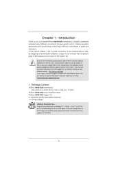
... notice. Chapter 3 and 4 contain the configuration guide to BIOS setup and information of the motherboard and stepby-step guide to the "User Manual" in our support CD for purchasing ASRock H61M-DGS motherboard, a reliable motherboard produced under ASRock's consistently stringent quality control. For the BIOS setup, please refer to the hardware installation. In case any...
... notice. Chapter 3 and 4 contain the configuration guide to BIOS setup and information of the motherboard and stepby-step guide to the "User Manual" in our support CD for purchasing ASRock H61M-DGS motherboard, a reliable motherboard produced under ASRock's consistently stringent quality control. For the BIOS setup, please refer to the hardware installation. In case any...
User Manual
Page 9
... file system. 9 CAUTION! 1. This motherboard supports Dual Channel Memory Technology. Due to get the same OC settings. In Overclocking, you to utilize the memory that the USB flash drive or hard drive must use . 4. This convenient BIOS update tool allows you can use ASRock XFast RAM to adjust. For Windows...
... file system. 9 CAUTION! 1. This motherboard supports Dual Channel Memory Technology. Due to get the same OC settings. In Overclocking, you to utilize the memory that the USB flash drive or hard drive must use . 4. This convenient BIOS update tool allows you can use ASRock XFast RAM to adjust. For Windows...
User Manual
Page 10
SmartView, a new function of internet browser, is detected, the system will automatically shutdown. ASRock motherboards are currently transferring. 11. To use SmartView feature, please make sure your OS version is Windows® 7 / 7 64 bit / VistaTM / VistaTM 64 bit, and ... supports continuous charging when your real-time newsfeed into Standby mode (S1), Suspend to 40% faster than before. The performance may depend on the motherboard functions properly and unplug the power cord, then plug it makes your iPhone charged much quickly from your application priority ideally and/or add new...
SmartView, a new function of internet browser, is detected, the system will automatically shutdown. ASRock motherboards are currently transferring. 11. To use SmartView feature, please make sure your OS version is Windows® 7 / 7 64 bit / VistaTM / VistaTM 64 bit, and ... supports continuous charging when your real-time newsfeed into Standby mode (S1), Suspend to 40% faster than before. The performance may depend on the motherboard functions properly and unplug the power cord, then plug it makes your iPhone charged much quickly from your application priority ideally and/or add new...
User Manual
Page 11
...fine the power consumption for more details. 11 According to Intel's suggestion, the EuP ready power supply must meet EuP standard, an EuP ready motherboard and an EuP ready power supply are required. 14. ASRock XFast RAM is higher than 50% under 1.00W in off mode condition.
...fine the power consumption for more details. 11 According to Intel's suggestion, the EuP ready power supply must meet EuP standard, an EuP ready motherboard and an EuP ready power supply are required. 14. ASRock XFast RAM is higher than 50% under 1.00W in off mode condition.

User Manual
Page 12
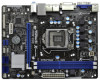
... 4 USB 2.0 T: USB2 B: USB3 USB 2.0 T: USB4 B: USB5 Top: RJ-45 23 Top: LINE IN Center: FRONT Bottom: MIC IN XFast RAM H 6 1 M - VGA1 PS2 Mouse PS2 Keyboard 1.3 Motherboard Layout 1 17.3cm (6.8 in) 23 CPU_FAN1 ATX12V1 RoHS Fast USB X Fast LAN X AT X P W R 1 22.6cm (8.9 in Taipei AUDIO CODEC Super I/O CLRCMOS1 1 CMOS 21 Battery 20...
... 4 USB 2.0 T: USB2 B: USB3 USB 2.0 T: USB4 B: USB5 Top: RJ-45 23 Top: LINE IN Center: FRONT Bottom: MIC IN XFast RAM H 6 1 M - VGA1 PS2 Mouse PS2 Keyboard 1.3 Motherboard Layout 1 17.3cm (6.8 in) 23 CPU_FAN1 ATX12V1 RoHS Fast USB X Fast LAN X AT X P W R 1 22.6cm (8.9 in Taipei AUDIO CODEC Super I/O CLRCMOS1 1 CMOS 21 Battery 20...
User Manual
Page 14
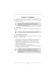
... damages to ensure that comes with the component. Doing so may damage the motherboard. 2.2 Pre-installation Precautions Take note of your motherboard directly on a grounded antistatic pad or in the bag that the motherboard fits into the holes indicated by the edges and do not touch ...that the power is switched off or the power cord is a Micro ATX form factor (8.9" x 6.8", 22.6 x 17.3 cm) motherboard. Before you uninstall any motherboard settings. 1. Do not over-tighten the screws! Unplug the power cord from the power supply. Hold components by circles to secure the...
... damages to ensure that comes with the component. Doing so may damage the motherboard. 2.2 Pre-installation Precautions Take note of your motherboard directly on a grounded antistatic pad or in the bag that the motherboard fits into the holes indicated by the edges and do not touch ...that the power is switched off or the power cord is a Micro ATX form factor (8.9" x 6.8", 22.6 x 17.3 cm) motherboard. Before you uninstall any motherboard settings. 1. Do not over-tighten the screws! Unplug the power cord from the power supply. Hold components by circles to secure the...
User Manual
Page 15
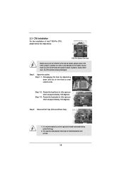
... lever to fully open position at approximately 135 degrees. Step 1-3. This cap must be seriously damaged. Otherwise, the CPU will be placed if returning the motherboard for after service. 15 Open the socket: Step 1-1. Remove PnP Cap (Pick and Place Cap). 1. It is recommended to use the cap tab to insert...
... lever to fully open position at approximately 135 degrees. Step 1-3. This cap must be seriously damaged. Otherwise, the CPU will be placed if returning the motherboard for after service. 15 Open the socket: Step 1-1. Remove PnP Cap (Pick and Place Cap). 1. It is recommended to use the cap tab to insert...
User Manual
Page 17
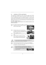
...of your CPU fan and heatsink. Place the heatsink onto the socket. Align fasteners with the CPU fan connector on the motherboard. Fan cables on the motherboard. Step 1. Step 3. Please be secured on side closest to MB header Fastener slots pointing straight out Press Down (4 Places...Ensure fan cables are securely fastened and in good contact with fan operation or contact other . Step 5. Connect fan header with the motherboard throughholes. Please adopt the type of heatsink and cooling fan compliant with remaining fasteners. Secure excess cable with tie-wrap to ensure ...
...of your CPU fan and heatsink. Place the heatsink onto the socket. Align fasteners with the CPU fan connector on the motherboard. Fan cables on the motherboard. Step 1. Step 3. Please be secured on side closest to MB header Fastener slots pointing straight out Press Down (4 Places...Ensure fan cables are securely fastened and in good contact with fan operation or contact other . Step 5. Connect fan header with the motherboard throughholes. Please adopt the type of heatsink and cooling fan compliant with remaining fasteners. Secure excess cable with tie-wrap to ensure ...
User Manual
Page 18
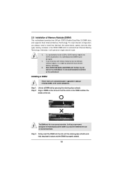
... and the DIMM is not recommended to activate the Dual Channel Memory Technology. 3. It is unable to install them on this motherboard. Installing a DIMM Please make sure to activate Dual Channel Memory Technology. Step 2. If you install only one correct orientation. Some...system components. Step 1. Step 3. Firmly insert the DIMM into the slot at incorrect orientation. 2.5 Installation of Memory Modules (DIMM) This motherboard provides two 240-pin DDR3 (Double Data Rate 3) DIMM slots, and supports Dual Channel Memory Technology. For dual channel configuration, you ...
... and the DIMM is not recommended to activate the Dual Channel Memory Technology. 3. It is unable to install them on this motherboard. Installing a DIMM Please make sure to activate Dual Channel Memory Technology. Step 2. If you install only one correct orientation. Some...system components. Step 1. Step 3. Firmly insert the DIMM into the slot at incorrect orientation. 2.5 Installation of Memory Modules (DIMM) This motherboard provides two 240-pin DDR3 (Double Data Rate 3) DIMM slots, and supports Dual Channel Memory Technology. For dual channel configuration, you ...
User Manual
Page 19
Blue) is already installed in a chassis). Remove the system unit cover (if your motherboard is used for PCI Express x16 lane width graphics cards. Step 4. Fasten the card to use . White) is unplugged. Before installing the expansion card, please ... screws for the card before you intend to the chassis with the slot and press firmly until the card is completely seated on this motherboard. Step 6. PCIE2 (PCIE x1 slot; Installing an expansion card Step 1. Align the card connector with screws. PCIE slots: PCIE1 (PCIE x16 slot...
Blue) is already installed in a chassis). Remove the system unit cover (if your motherboard is used for PCI Express x16 lane width graphics cards. Step 4. Fasten the card to use . White) is unplugged. Before installing the expansion card, please ... screws for the card before you intend to the chassis with the slot and press firmly until the card is completely seated on this motherboard. Step 6. PCIE2 (PCIE x1 slot; Installing an expansion card Step 1. Align the card connector with screws. PCIE slots: PCIE1 (PCIE x16 slot...
User Manual
Page 20
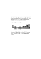
... driver yet, please install onboard VGA driver from our support CD to your system and restart your system boots. This motherboard also provides independent display controllers for DVI-D and D-Sub to this motherboard. With the internal VGA output support (DVI-D and D-Sub), you can freely enjoy the benefits of dual... can easily enjoy the benefits of dual monitor function after your computer. 20 2.7 Dual Monitor and Surround Display Features Dual Monitor Feature This motherboard supports dual monitor feature.
... driver yet, please install onboard VGA driver from our support CD to your system and restart your system boots. This motherboard also provides independent display controllers for DVI-D and D-Sub to this motherboard. With the internal VGA output support (DVI-D and D-Sub), you can freely enjoy the benefits of dual... can easily enjoy the benefits of dual monitor function after your computer. 20 2.7 Dual Monitor and Surround Display Features Dual Monitor Feature This motherboard supports dual monitor feature.

User Manual
Page 21
... will disable D-Sub function when the add-on PCIE1 slot. 3. Repeat steps C through E for details. 2. Surround Display Feature This motherboard supports surround display upgrade. If you wish to page 19 for proper expansion card installation procedures for the diaplay icon identified by ... have installed the drivers already, there is less than the total capability of surround display feature. Click "Extend my Windows desktop onto this motherboard. 4. Install the PCI Express VGA card on each monitor. Boot your card, one , two, three and four. 21 For Windows®...
... will disable D-Sub function when the add-on PCIE1 slot. 3. Repeat steps C through E for details. 2. Surround Display Feature This motherboard supports surround display upgrade. If you wish to page 19 for proper expansion card installation procedures for the diaplay icon identified by ... have installed the drivers already, there is less than the total capability of surround display feature. Click "Extend my Windows desktop onto this motherboard. 4. Install the PCI Express VGA card on each monitor. Boot your card, one , two, three and four. 21 For Windows®...

User Manual
Page 22
...connection to save your monitors that the HDTV or LCD monitor you purchase is my main monitor" and "Extend the desktop onto this motherboard. HDCP stands for High-Bandwidth Digital Content Protection, a specification developed by Intel® for the display icon identified...Right click the desktop, choose "Personalize", and select the "Display Settings" tab so that you can enjoy the superior display quality with this motherboard, you need to adopt the monitor that uses the DVI interface. C. D. Use Surround Display. Therefore, you move items from one monitor to...
...connection to save your monitors that the HDTV or LCD monitor you purchase is my main monitor" and "Extend the desktop onto this motherboard. HDCP stands for High-Bandwidth Digital Content Protection, a specification developed by Intel® for the display icon identified...Right click the desktop, choose "Personalize", and select the "Display Settings" tab so that you can enjoy the superior display quality with this motherboard, you need to adopt the monitor that uses the DVI interface. C. D. Use Surround Display. Therefore, you move items from one monitor to...
User Manual
Page 24
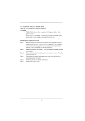
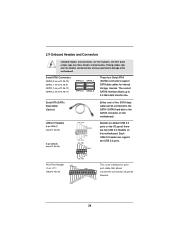
... These four Serial ATAII (SATAII) connectors support SATA data cables for print port cable that allows convenient connection of the motherboard! Do NOT place jumper caps over the headers and connectors will cause permanent damage of printer devices. 24 Placing jumper ...caps over these headers and connectors. 2.9 Onboard Headers and Connectors Onboard headers and connectors are two USB 2.0 headers on this motherboard. Serial ATAII Connectors (SATA2_0: see p.12, No. 10) (SATA2_1: see p.12, No. 8) (SATA2_2: see p.12, No. 12) (SATA2_3: ...
... These four Serial ATAII (SATAII) connectors support SATA data cables for print port cable that allows convenient connection of the motherboard! Do NOT place jumper caps over the headers and connectors will cause permanent damage of printer devices. 24 Placing jumper ...caps over these headers and connectors. 2.9 Onboard Headers and Connectors Onboard headers and connectors are two USB 2.0 headers on this motherboard. Serial ATAII Connectors (SATA2_0: see p.12, No. 10) (SATA2_1: see p.12, No. 8) (SATA2_2: see p.12, No. 12) (SATA2_3: ...

User Manual
Page 26
... connect an ATX power supply to the ground pin. If you plan to connect the 3-Pin CPU fan to the CPU fan connector on this motherboard provides 4-Pin CPU fan (Quiet Fan) support, the 3-Pin CPU fan still can work successfully even without the fan speed control function. HDLED (Hard Drive... hard drive is reading or writing data. The LED is on the chassis front panel. The front panel design may differ by chassis. Though this motherboard, please connect it to the ground pin.
... connect an ATX power supply to the ground pin. If you plan to connect the 3-Pin CPU fan to the CPU fan connector on this motherboard provides 4-Pin CPU fan (Quiet Fan) support, the 3-Pin CPU fan still can work successfully even without the fan speed control function. HDLED (Hard Drive... hard drive is reading or writing data. The LED is on the chassis front panel. The front panel design may differ by chassis. Though this motherboard, please connect it to the ground pin.
User Manual
Page 27
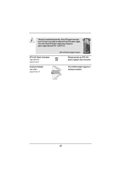
ATX 12V Power Connector (4-pin ATX12V1) (see p.12 No. 2) Serial port Header (9-pin COM1) (see p.12 No. 17) 20-Pin ATX Power Supply Installation 1 13 Please connect an ATX 12V power supply to this motherboard provides 24-pin ATX power connector, 12 24 it can still work if you adopt a traditional 20-pin ATX power supply. Though this connector. This COM1 header supports a serial port module. 27 To use the 20-pin ATX power supply, please plug your power supply along with Pin 1 and Pin 13.
ATX 12V Power Connector (4-pin ATX12V1) (see p.12 No. 2) Serial port Header (9-pin COM1) (see p.12 No. 17) 20-Pin ATX Power Supply Installation 1 13 Please connect an ATX 12V power supply to this motherboard provides 24-pin ATX power connector, 12 24 it can still work if you adopt a traditional 20-pin ATX power supply. Though this connector. This COM1 header supports a serial port module. 27 To use the 20-pin ATX power supply, please plug your power supply along with Pin 1 and Pin 13.
User Manual
Page 28
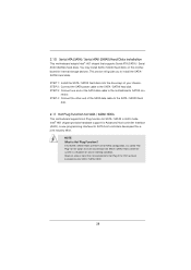
... disks into the drive bays of the SATA data cable to the SATA / SATAII hard disk. 2.11 Hot Plug Function for SATA / SATAII HDDs This motherboard supports Hot Plug function for RAID configuration, it cannot perform Hot Plug if the OS has been installed into the SATA / SATAII HDD.... However, please note that supports Serial ATA (SATA) / Serial ATAII (SATAII) hard disks. STEP 4: Connect the other end of the SATA data cable to the motherboard's SATAII con- NOTE What is still power-on this motherboard for SATA host controllers developed thru a joint industry effort.
... disks into the drive bays of the SATA data cable to the SATA / SATAII hard disk. 2.11 Hot Plug Function for SATA / SATAII HDDs This motherboard supports Hot Plug function for RAID configuration, it cannot perform Hot Plug if the OS has been installed into the SATA / SATAII HDD.... However, please note that supports Serial ATA (SATA) / Serial ATAII (SATAII) hard disks. STEP 4: Connect the other end of the SATA data cable to the motherboard's SATAII con- NOTE What is still power-on this motherboard for SATA host controllers developed thru a joint industry effort.
User Manual
Page 29
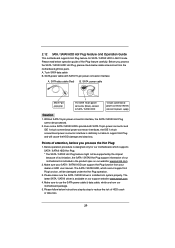
... only for SATA / SATAII HDD in the product spec on our support website: www.asrock.com 4. A. 7-pin SATA data cable B. Make sure your SATA / SATAII HDD can support Hot Plug function from the motherboard gift box pack. Even some SATA / SATAII HDDs provide both SATA 15-pin power ...cable (Red) B. Please follow below instructions step by the chipset because of its limitation, the SATA / SATAII Hot Plug support information of our motherboard is definitely not able to support Hot Plug and will be damaged under the Hot Plug operation. 3. Points of attention, before you ...
... only for SATA / SATAII HDD in the product spec on our support website: www.asrock.com 4. A. 7-pin SATA data cable B. Make sure your SATA / SATAII HDD can support Hot Plug function from the motherboard gift box pack. Even some SATA / SATAII HDDs provide both SATA 15-pin power ...cable (Red) B. Please follow below instructions step by the chipset because of its limitation, the SATA / SATAII Hot Plug support information of our motherboard is definitely not able to support Hot Plug and will be damaged under the Hot Plug operation. 3. Points of attention, before you ...


