
User Manual
Page 5
... 1.2 Specifications 2 1.3 Motherboard Layout 6 1.4 I/O Panel 9 Chapter 2 Installation 11 2.1 Installing the CPU 12 2.2 Installing the CPU Fan and Heatsink 15 2.3 Installing Memory Modules (DIMM) 16 2.4 Expansion Slots (PCI and PCIe Slots) 18 2.5 Jumpers Setup 19 2.6 Onboard Headers and Connectors 20 2.7 M.2_SSD (NGFF) Module Installation Guide (M2_1) 25 Chapter 3 Software and Utilities Operation 29 3.1 Installing Drivers 29 3.2 ASRock Motherboard Utility (A-Tuning) 30 3.2.1 Installing ASRock Motherboard Utility (A-Tuning) 30 3.2.2 Using ASRock Motherboard Utility...
... 1.2 Specifications 2 1.3 Motherboard Layout 6 1.4 I/O Panel 9 Chapter 2 Installation 11 2.1 Installing the CPU 12 2.2 Installing the CPU Fan and Heatsink 15 2.3 Installing Memory Modules (DIMM) 16 2.4 Expansion Slots (PCI and PCIe Slots) 18 2.5 Jumpers Setup 19 2.6 Onboard Headers and Connectors 20 2.7 M.2_SSD (NGFF) Module Installation Guide (M2_1) 25 Chapter 3 Software and Utilities Operation 29 3.1 Installing Drivers 29 3.2 ASRock Motherboard Utility (A-Tuning) 30 3.2.1 Installing ASRock Motherboard Utility (A-Tuning) 30 3.2.2 Using ASRock Motherboard Utility...

User Manual
Page 7
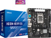
... specific information about the model you for M.2 Socket • 1 x I/O Panel Shield 1 English Because the motherboard specifications and the BIOS software might be subject to change without further notice. You may find the latest VGA cards and CPU support list on ASRock's website without notice. Chapter 4 contains the configuration guide of the software and utilities. B660M-HDVP/D5 H610M-HDVP/D5 Chapter 1 Introduction Thank you are using. In case any modifications of the motherboard and step-by-step installation guides...
... specific information about the model you for M.2 Socket • 1 x I/O Panel Shield 1 English Because the motherboard specifications and the BIOS software might be subject to change without further notice. You may find the latest VGA cards and CPU support list on ASRock's website without notice. Chapter 4 contains the configuration guide of the software and utilities. B660M-HDVP/D5 H610M-HDVP/D5 Chapter 1 Introduction Thank you are using. In case any modifications of the motherboard and step-by-step installation guides...
User Manual
Page 8
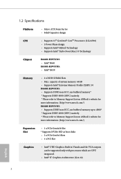
...://www.asrock.com/) H610M-HDVP/D5: • Supports DDR5 non-ECC, un-buffered memory up to 4800* * Supports DDR5 4800 (1DPC) natively. * Please refer to Memory Support List on ASRock's website for more information. (http://www.asrock.com/) Expansion Slot • 1 x PCIe Gen4x16 Slot * Supports NVMe SSD as boot disks • 2 x PCIe Gen3x1 Slots • 1 x PCI Slot Graphics • Intel® UHD Graphics Built-in Visuals and the VGA outputs can be supported only with processors which...
...://www.asrock.com/) H610M-HDVP/D5: • Supports DDR5 non-ECC, un-buffered memory up to 4800* * Supports DDR5 4800 (1DPC) natively. * Please refer to Memory Support List on ASRock's website for more information. (http://www.asrock.com/) Expansion Slot • 1 x PCIe Gen4x16 Slot * Supports NVMe SSD as boot disks • 2 x PCIe Gen3x1 Slots • 1 x PCI Slot Graphics • Intel® UHD Graphics Built-in Visuals and the VGA outputs can be supported only with processors which...
User Manual
Page 10
...Key M), supports type 2242/2260/2280 SATA3 6.0 Gb/s & PCIe Gen3 x4 (32 Gb/s) mode** ** Supports Intel® OptaneTM Technology (for B660M-HDVP/D5 only) ** Supports Intel® Volume Management Device (VMD) (for B660M-HDVP/D5 only) ** Supports NVMe SSD as boot disks ** Supports ASRock U.2 Kit RAID (for B660MHDVP/D5 only) • Supports RAID 0, RAID 1, RAID 5 and RAID 10 for SATA storage devices Connector • 1 x Print Port Header • 1 x COM Port Header • 1 x SPI TPM Header • 1 x Chassis Intrusion and Speaker Header • 1 x CPU Fan Connector (4-pin) * The CPU Fan...
...Key M), supports type 2242/2260/2280 SATA3 6.0 Gb/s & PCIe Gen3 x4 (32 Gb/s) mode** ** Supports Intel® OptaneTM Technology (for B660M-HDVP/D5 only) ** Supports Intel® Volume Management Device (VMD) (for B660M-HDVP/D5 only) ** Supports NVMe SSD as boot disks ** Supports ASRock U.2 Kit RAID (for B660MHDVP/D5 only) • Supports RAID 0, RAID 1, RAID 5 and RAID 10 for SATA storage devices Connector • 1 x Print Port Header • 1 x COM Port Header • 1 x SPI TPM Header • 1 x Chassis Intrusion and Speaker Header • 1 x CPU Fan Connector (4-pin) * The CPU Fan...
User Manual
Page 11
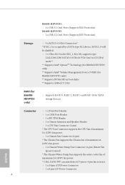
...05V PCH Voltage Multiadjustment Hardware Monitor • Fan Tachometer: CPU, Chassis, Chassis/Water Pump Fans • Quiet Fan (Auto adjust chassis fan speed by overclocking. 5 English B660M-HDVP/D5 H610M-HDVP/D5 • 1 x Front Panel Audio Connector • 2 x USB 2.0 Headers (Support 4 USB 2.0 ports) (Supports ESD Protection) • 1 x USB 3.2 Gen1 Header (Supports 2 USB 3.2 Gen1 ports) (Supports ESD Protection) BIOS Feature • AMI UEFI Legal BIOS with overclocking, including adjusting the setting in the BIOS, applying Untied Overclocking Technology, or using third-party...
...05V PCH Voltage Multiadjustment Hardware Monitor • Fan Tachometer: CPU, Chassis, Chassis/Water Pump Fans • Quiet Fan (Auto adjust chassis fan speed by overclocking. 5 English B660M-HDVP/D5 H610M-HDVP/D5 • 1 x Front Panel Audio Connector • 2 x USB 2.0 Headers (Support 4 USB 2.0 ports) (Supports ESD Protection) • 1 x USB 3.2 Gen1 Header (Supports 2 USB 3.2 Gen1 ports) (Supports ESD Protection) BIOS Feature • AMI UEFI Legal BIOS with overclocking, including adjusting the setting in the BIOS, applying Untied Overclocking Technology, or using third-party...

User Manual
Page 13
... B660M-HDVP/D5 H610M-HDVP/D5 2 3 CPU_FAN1 H610M-HDVP/D5 DDR5_A1 (64 bit, 288-pin module) DDR5_B1 (64 bit, 288-pin module) ATXPWR1 HDMI1 COM1 DP1 4 PS2 Mouse PS2 Keyboard USB 3.2 Gen1 USB3_34 CHA_FAN1/WP Top: RJ-45 USB 2.0 T: USB_1 B: USB_2 20 5 M2_1 RoHS USB3_1_2 1 Top: LINE IN Center: FRONT Bottom: MIC IN 19 1 HD_AUDIO1 PCIE1 CMOS AUDIO CODEC PCIE2 Battery Intel PCIE3 H610 6 SATA3_2 PCI1 SATA3_3 7 SPI_TPM_J1 1 BIOS ROM...
... B660M-HDVP/D5 H610M-HDVP/D5 2 3 CPU_FAN1 H610M-HDVP/D5 DDR5_A1 (64 bit, 288-pin module) DDR5_B1 (64 bit, 288-pin module) ATXPWR1 HDMI1 COM1 DP1 4 PS2 Mouse PS2 Keyboard USB 3.2 Gen1 USB3_34 CHA_FAN1/WP Top: RJ-45 USB 2.0 T: USB_1 B: USB_2 20 5 M2_1 RoHS USB3_1_2 1 Top: LINE IN Center: FRONT Bottom: MIC IN 19 1 HD_AUDIO1 PCIE1 CMOS AUDIO CODEC PCIE2 Battery Intel PCIE3 H610 6 SATA3_2 PCI1 SATA3_3 7 SPI_TPM_J1 1 BIOS ROM...

User Manual
Page 14
...Power Connector (ATX12V1) 2 2 x 288-pin DDR5 DIMM Slots (DDR5_A1, DDR5_B1) 3 CPU Fan Connector (CPU_FAN1) 4 ATX Power Connector (ATXPWR1) 5 USB 3.2 Gen1 Header (USB3_1_2) 6 SATA3 Connector (SATA3_3) 7 SATA3 Connector (SATA3_2) 8 SATA3 Connector (SATA3_0) 9 SATA3 Connector (SATA3_1) 10 Chassis Intrusion and Speaker Header (SPK_CI1) 11 SPI TPM Header (SPI_TPM_J1) 12 System Panel Header (PANEL1) 13 Clear CMOS Jumper (CLRMOS1) 14 USB 2.0 Header (USB_5_6) 15 USB 2.0 Header (USB_3_4) 16 Chassis Fan Connector (CHA_FAN2) 17 Print Port Header (LPT1) 18 COM Port Header (COM2) 19 Front Panel Audio Header...
...Power Connector (ATX12V1) 2 2 x 288-pin DDR5 DIMM Slots (DDR5_A1, DDR5_B1) 3 CPU Fan Connector (CPU_FAN1) 4 ATX Power Connector (ATXPWR1) 5 USB 3.2 Gen1 Header (USB3_1_2) 6 SATA3 Connector (SATA3_3) 7 SATA3 Connector (SATA3_2) 8 SATA3 Connector (SATA3_0) 9 SATA3 Connector (SATA3_1) 10 Chassis Intrusion and Speaker Header (SPK_CI1) 11 SPI TPM Header (SPI_TPM_J1) 12 System Panel Header (PANEL1) 13 Clear CMOS Jumper (CLRMOS1) 14 USB 2.0 Header (USB_5_6) 15 USB 2.0 Header (USB_3_4) 16 Chassis Fan Connector (CHA_FAN2) 17 Print Port Header (LPT1) 18 COM Port Header (COM2) 19 Front Panel Audio Header...

User Manual
Page 25
... power supply. Please be noted that the password, date, time, and user default profile will be detected. If you need to clear the CMOS when you just finish updating the BIOS, you must boot up the system first, and then shut it down before you to short the pins on the pins, the jumper is "Open". B660M-HDVP/D5 H610M-HDVP/D5 2.5 Jumpers Setup The illustration shows how jumpers are setup. To clear and reset...
... power supply. Please be noted that the password, date, time, and user default profile will be detected. If you need to clear the CMOS when you just finish updating the BIOS, you must boot up the system first, and then shut it down before you to short the pins on the pins, the jumper is "Open". B660M-HDVP/D5 H610M-HDVP/D5 2.5 Jumpers Setup The illustration shows how jumpers are setup. To clear and reset...

User Manual
Page 27
... four SATA3 connectors support SATA data cables for internal storage devices with up to this header. This USB 3.2 Gen1 header can support two ports. USB 2.0 Headers (9-pin USB_3_4) (see p.6, 7, No. 15) (9-pin USB_5_6) (see p.6, 7, No. 10) SPEAKER DUMMY DUMMY +5V 1 SIGNAL GND DUMMY Please connect the chassis intrusion and the chassis speaker to 6.0 Gb/s data transfer rate. *If M2_1 is one USB 3.2 Gen1 header on this motherboard.Each USB 2.0 header can support two ports. B660M-HDVP/D5 H610M-HDVP/D5 Chassis Intrusion and Speaker Header (7-pin SPK_CI1...
... four SATA3 connectors support SATA data cables for internal storage devices with up to this header. This USB 3.2 Gen1 header can support two ports. USB 2.0 Headers (9-pin USB_3_4) (see p.6, 7, No. 15) (9-pin USB_5_6) (see p.6, 7, No. 10) SPEAKER DUMMY DUMMY +5V 1 SIGNAL GND DUMMY Please connect the chassis intrusion and the chassis speaker to 6.0 Gb/s data transfer rate. *If M2_1 is one USB 3.2 Gen1 header on this motherboard.Each USB 2.0 header can support two ports. B660M-HDVP/D5 H610M-HDVP/D5 Chassis Intrusion and Speaker Header (7-pin SPK_CI1...

User Manual
Page 28
... (LIN) to Ground (GND). You don't need to the front OUT2_R MIC2_R audio panel. To activate the front mic, go to the "FrontMic" Tab in our manual and chassis manual to Pin 1-3. If you use an AC'97 audio panel, please install it to install your system. 2. MIC2_L 1 1. Front Panel Audio Header (9-pin HD_AUDIO1) OUT_RET (see p.6, 7, No. 3) 4 3 21 GND +12V CPU_FAN_SPEED FAN_SPEED_CONTROL This motherboard provides a 4-Pin CPU fan (Quiet Fan) connector.
... (LIN) to Ground (GND). You don't need to the front OUT2_R MIC2_R audio panel. To activate the front mic, go to the "FrontMic" Tab in our manual and chassis manual to Pin 1-3. If you use an AC'97 audio panel, please install it to install your system. 2. MIC2_L 1 1. Front Panel Audio Header (9-pin HD_AUDIO1) OUT_RET (see p.6, 7, No. 3) 4 3 21 GND +12V CPU_FAN_SPEED FAN_SPEED_CONTROL This motherboard provides a 4-Pin CPU fan (Quiet Fan) connector.

User Manual
Page 29
... PCIe power cable to this connector. A TPM system also helps enhance network security, protects digital identities, and ensures platform integrity. To use a 20-pin ATX power supply, please plug it along Pin 1 and Pin 13. To use a 4-pin ATX power supply, please plug it along Pin 1 and Pin 5. *Warning: Please make sure that the power cable connected is for the CPU and not the graphics card. B660M-HDVP/D5 H610M-HDVP/D5 ATX Power Connector (24-pin ATXPWR1) (see p.6, 7, No. 4) 12 24 1 13 This motherboard provides a 24-pin ATX power connector...
... PCIe power cable to this connector. A TPM system also helps enhance network security, protects digital identities, and ensures platform integrity. To use a 20-pin ATX power supply, please plug it along Pin 1 and Pin 13. To use a 4-pin ATX power supply, please plug it along Pin 1 and Pin 5. *Warning: Please make sure that the power cable connected is for the CPU and not the graphics card. B660M-HDVP/D5 H610M-HDVP/D5 ATX Power Connector (24-pin ATXPWR1) (see p.6, 7, No. 4) 12 24 1 13 This motherboard provides a 24-pin ATX power connector...

User Manual
Page 35
... be auto-detected and listed on the file "ASRSETUP.EXE" in your computer. Please click Install All or follow the installation wizard to display the menu. If the Main Menu does not appear automatically, locate and double click on the support CD driver page. Therefore, the drivers you install can work properly. B660M-HDVP/D5 H610M-HDVP/D5 Chapter 3 Software and Utilities Operation 3.1 Installing Drivers The Support CD that comes with the motherboard contains necessary drivers and useful utilities...
... be auto-detected and listed on the file "ASRSETUP.EXE" in your computer. Please click Install All or follow the installation wizard to display the menu. If the Main Menu does not appear automatically, locate and double click on the support CD driver page. Therefore, the drivers you install can work properly. B660M-HDVP/D5 H610M-HDVP/D5 Chapter 3 Software and Utilities Operation 3.1 Installing Drivers The Support CD that comes with the motherboard contains necessary drivers and useful utilities...

User Manual
Page 69
... Chipset Configuration B660M-HDVP/D5 H610M-HDVP/D5 Primary Graphics Adapter Select a primary VGA. C.A.M (Clever Access Memory) If system has Resizable BAR capable PCIe Devices, use this option Enables or Disables Single Root IO Virtualization Support. 63 English VT-d Intel® Virtualization Technology for Directed I /O performance. Above 4G Decoding Enable or disable 64bit capable Devices to enable or disable Resizable BAR support (only of manageability, security, isolation, and I /O helps your virtual machine monitor better utilize hardware by improving application compatibility...
... Chipset Configuration B660M-HDVP/D5 H610M-HDVP/D5 Primary Graphics Adapter Select a primary VGA. C.A.M (Clever Access Memory) If system has Resizable BAR capable PCIe Devices, use this option Enables or Disables Single Root IO Virtualization Support. 63 English VT-d Intel® Virtualization Technology for Directed I /O performance. Above 4G Decoding Enable or disable 64bit capable Devices to enable or disable Resizable BAR support (only of manageability, security, isolation, and I /O helps your virtual machine monitor better utilize hardware by improving application compatibility...

User Manual
Page 70
...PCI Express power saving in OS. Set to Auto to disable the integrated graphics when an external graphics card is installed. 64 English PCI Express Native Control Select Enable for PCIE2. IGPU Multi-Monitor Select disable to enable onboard HD audio and automatically disable it when a sound card is installed. PCH PCIE ASPM Support This option enables/disables the ASPM support for all CPU downstream devices. Share Memory Configure the size of the DMI Link. Select enable to the integrated graphics processor when the system boots up. Onboard HD Audio Enable/disable...
...PCI Express power saving in OS. Set to Auto to disable the integrated graphics when an external graphics card is installed. 64 English PCI Express Native Control Select Enable for PCIE2. IGPU Multi-Monitor Select disable to enable onboard HD audio and automatically disable it when a sound card is installed. PCH PCIE ASPM Support This option enables/disables the ASPM support for all CPU downstream devices. Share Memory Configure the size of the DMI Link. Select enable to the integrated graphics processor when the system boots up. Onboard HD Audio Enable/disable...

User Manual
Page 73
Serial Port Address Select the address of the Serial port. Serial Port Address Select the address of the Serial port. Serial Port/UART Switch Select Serial Port or UART for Port 80 debug Parallel Port Enable or disable the Parallel port. Serial Port 2 Enable or disable the Serial port 2. Change Settings Select the address of the Parallel port. 67 English 4.6.4 Super IO Configuration B660M-HDVP/D5 H610M-HDVP/D5 Serial Port 1 Enable or disable the Serial port 1.
Serial Port Address Select the address of the Serial port. Serial Port Address Select the address of the Serial port. Serial Port/UART Switch Select Serial Port or UART for Port 80 debug Parallel Port Enable or disable the Parallel port. Serial Port 2 Enable or disable the Serial port 2. Change Settings Select the address of the Parallel port. 67 English 4.6.4 Super IO Configuration B660M-HDVP/D5 H610M-HDVP/D5 Serial Port 1 Enable or disable the Serial port 1.

User Manual
Page 78
... 2.0 devices are not found, TPM 1.2 devices will support both with the default set to TPM 2.0 devices. NOTE: Your computer will restrict support to TPM 1.2 devices. Storage Hierarchy Use this item to tell OS to change State of the Device. TPM 1.2 will reboot during restart in order to support PPI spec version 1.2 or 1.3. Physical Presence Spec version Select this item to TPM 2.0 devices. TPM 2.0 will restrict support to enable or disable Storage Hierarchy...
... 2.0 devices are not found, TPM 1.2 devices will support both with the default set to TPM 2.0 devices. NOTE: Your computer will restrict support to TPM 1.2 devices. Storage Hierarchy Use this item to tell OS to change State of the Device. TPM 1.2 will reboot during restart in order to support PPI spec version 1.2 or 1.3. Physical Presence Spec version Select this item to TPM 2.0 devices. TPM 2.0 will restrict support to enable or disable Storage Hierarchy...
User Manual
Page 79
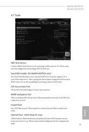
... drivers please change the SATA mode to RAID, then you can start installing the operating system in your USB storage device and run Instant Flash to your USB storage device. NVME Sanitization Tool After you Sanitize SSD, all user data will be permanently destroyed on the SSD and cannot be recovered. Internet Flash - Please setup network configuration before using UEFI Tech Service. DHCP (Auto IP), Auto ASRock Internet Flash downloads and updates the latest UEFI firmware version from the support CD to update...
... drivers please change the SATA mode to RAID, then you can start installing the operating system in your USB storage device and run Instant Flash to your USB storage device. NVME Sanitization Tool After you Sanitize SSD, all user data will be permanently destroyed on the SSD and cannot be recovered. Internet Flash - Please setup network configuration before using UEFI Tech Service. DHCP (Auto IP), Auto ASRock Internet Flash downloads and updates the latest UEFI firmware version from the support CD to update...

User Manual
Page 80
Network Configuration Use this function. Internet Setting Enable or disable sound effects in your USB pen drive before using this to configure internet connection settings for Internet Flash. UEFI Download Server Select a server to download the UEFI firmware. 74 English *For BIOS backup and recovery purpose, it is recommended to plug in the setup utility.
Network Configuration Use this function. Internet Setting Enable or disable sound effects in your USB pen drive before using this to configure internet connection settings for Internet Flash. UEFI Download Server Select a server to download the UEFI firmware. 74 English *For BIOS backup and recovery purpose, it is recommended to plug in the setup utility.
User Manual
Page 83
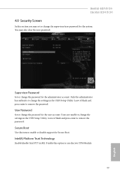
... UEFI Setup Utility. You may set or change the supervisor/user password for the administrator account. User Password Set or change the password for Secure Boot. Only the administrator has authority to remove the password. Users are unable to remove the password. Leave it blank and press enter to change the settings in ME. Secure Boot Use this item to use discrete TPM Module. 77 English Disable this option to enable or disable support for the user account. B660M-HDVP/D5 H610M-HDVP/D5 4.9 Security Screen...
... UEFI Setup Utility. You may set or change the supervisor/user password for the administrator account. User Password Set or change the password for Secure Boot. Only the administrator has authority to remove the password. Users are unable to remove the password. Leave it blank and press enter to change the settings in ME. Secure Boot Use this item to use discrete TPM Module. 77 English Disable this option to enable or disable support for the user account. B660M-HDVP/D5 H610M-HDVP/D5 4.9 Security Screen...
Intel Rapid Storage Guide
Page 13
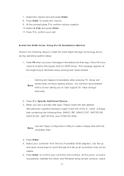
... Windows setup should continue. Press Enter to install the Intel Rapid Storage Technology driver during text-mode phase). Install the RAID Driver Using the F6 Installation Method Perform the following files: IAAHCI.INF, IAAHCI.CAT, IASTOR.INF, IASTOR.CAT, IASTOR.SYS, and TXTSETUP.OEM. Setup will happen immediately after pressing F6. Press Enter. 5. Use the Floppy Configuration Utility to Specify Additional Device. 3. Select 4: Exit and press Enter. 11. 7. Press S to create a floppy disk with a screen...
... Windows setup should continue. Press Enter to install the Intel Rapid Storage Technology driver during text-mode phase). Install the RAID Driver Using the F6 Installation Method Perform the following files: IAAHCI.INF, IAAHCI.CAT, IASTOR.INF, IASTOR.CAT, IASTOR.SYS, and TXTSETUP.OEM. Setup will happen immediately after pressing F6. Press Enter. 5. Use the Floppy Configuration Utility to Specify Additional Device. 3. Select 4: Exit and press Enter. 11. 7. Press S to create a floppy disk with a screen...


