
User Manual
Page 3
... Contents 5 1.2 Specifications 6 1.3 Motherboard Layout 11 1.4 I/O Panel 12 2 Installation 13 2.1 Screw Holes 13 2.2 Pre-installation Precautions 13 2.3 CPU Installation 14 2.4 Installation of Heatsink and CPU fan 16 2.5 Installation of Memory Modules (DIMM 17 2.6 Expansion Slots (PCI and PCI Express Slots 19 2.7 Jumpers Setup 20 2.8 Onboard Headers... BIOS Menu Bar 31 3.1.2 Navigation Keys 31 3.2 Main Screen 32 3.3 OC Tweaker Screen 33 3.4 Advanced Screen 37 3.4.1 CPU Configuration 38 3.4.2 Chipset Configuration 40 3.4.3 ACPI Configuration 41 3.4.4 Storage Configuration 42 3
... Contents 5 1.2 Specifications 6 1.3 Motherboard Layout 11 1.4 I/O Panel 12 2 Installation 13 2.1 Screw Holes 13 2.2 Pre-installation Precautions 13 2.3 CPU Installation 14 2.4 Installation of Heatsink and CPU fan 16 2.5 Installation of Memory Modules (DIMM 17 2.6 Expansion Slots (PCI and PCI Express Slots 19 2.7 Jumpers Setup 20 2.8 Onboard Headers... BIOS Menu Bar 31 3.1.2 Navigation Keys 31 3.2 Main Screen 32 3.3 OC Tweaker Screen 33 3.4 Advanced Screen 37 3.4.1 CPU Configuration 38 3.4.2 Chipset Configuration 40 3.4.3 ACPI Configuration 41 3.4.4 Storage Configuration 42 3

User Manual
Page 5
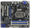
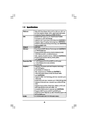
...CPU support lists on ASRock website without notice. Because the motherboard specifications and the BIOS software might be updated, the content of this manual occur, the updated version will be available on ASRock website as well. www.asrock.com/support/index.asp 1.1 Package Contents ASRock H55M-GE... Motherboard (Micro ATX Form Factor: 9.6-in x 8.7-in, 24.4 cm x 22.1 cm) ASRock H55M-GE Quick Installation Guide ASRock H55M-GE Support CD 2 x Serial ATA (SATA...
...CPU support lists on ASRock website without notice. Because the motherboard specifications and the BIOS software might be updated, the content of this manual occur, the updated version will be available on ASRock website as well. www.asrock.com/support/index.asp 1.1 Package Contents ASRock H55M-GE... Motherboard (Micro ATX Form Factor: 9.6-in x 8.7-in, 24.4 cm x 22.1 cm) ASRock H55M-GE Quick Installation Guide ASRock H55M-GE Support CD 2 x Serial ATA (SATA...
User Manual
Page 6
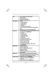
... Graphics * Audio - Supports Intel® Turbo Boost Technology (see CAUTION 4) - 4 x DDR3 DIMM slots - Supports EM64T CPU - Dual Channel DDR3 Memory Technology (see CAUTION 1) - Supports D-Sub with DVI and HDMI ports - resolution up to 1920x1200... HDMI 1.3a Technology with Intel® Graphics Technology - Pixel Shader 4.0, DirectX 10 - All Solid Capacitor design (100% Japan-made high-quality Conductive Polymer Capacitors) (H55M-GE R2.0) - Intel® H55 - Supports Intel® Extreme Memory Profile (XMP) (see CAUTION 6) - 1 x PCI Express 2.0 x16 slot (5GT/s at ...
... Graphics * Audio - Supports Intel® Turbo Boost Technology (see CAUTION 4) - 4 x DDR3 DIMM slots - Supports EM64T CPU - Dual Channel DDR3 Memory Technology (see CAUTION 1) - Supports D-Sub with DVI and HDMI ports - resolution up to 1920x1200... HDMI 1.3a Technology with Intel® Graphics Technology - Pixel Shader 4.0, DirectX 10 - All Solid Capacitor design (100% Japan-made high-quality Conductive Polymer Capacitors) (H55M-GE R2.0) - Intel® H55 - Supports Intel® Extreme Memory Profile (XMP) (see CAUTION 6) - 1 x PCI Express 2.0 x16 slot (5GT/s at ...
User Manual
Page 7
... Ready-to-Use USB 2.0 Ports - 1 x RJ-45 LAN Port with LED (ACT/LINK LED and SPEED LED) - CPU/Chassis/Power FAN connector - 24 pin ATX power connector - 4 pin 12V power connector - Supports jumperfree - ASRock Instant Flash (see CAUTION 10) - 1 x IR header - 1 x Print Port header - 1 x COM port header...10/100/1000 Mb/s - Supports Wake-On-LAN - ACPI 1.1 Compliance Wake Up Events - Drivers, Utilities, AntiVirus Software (Trial Version), ASRock Software Suite (CyberLink DVD Suite and Creative Sound Blaster X-Fi MB) (OEM and Trial Version) - Realtek RTL8111E - Supports LAN Cable ...
... Ready-to-Use USB 2.0 Ports - 1 x RJ-45 LAN Port with LED (ACT/LINK LED and SPEED LED) - CPU/Chassis/Power FAN connector - 24 pin ATX power connector - 4 pin 12V power connector - Supports jumperfree - ASRock Instant Flash (see CAUTION 10) - 1 x IR header - 1 x Print Port header - 1 x COM port header...10/100/1000 Mb/s - Supports Wake-On-LAN - ACPI 1.1 Compliance Wake Up Events - Drivers, Utilities, AntiVirus Software (Trial Version), ASRock Software Suite (CyberLink DVD Suite and Creative Sound Blaster X-Fi MB) (OEM and Trial Version) - Realtek RTL8111E - Supports LAN Cable ...

User Manual
Page 8
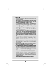
...CPU/Chassis/Power Fan Tachometer - CPU/Chassis Fan Multi-Speed Control - ASRock U-COP (see CAUTION 15) - FCC, CE, WHQL - ErP/EuP Ready (ErP/EuP ready power supply is required) (see CAUTION 19) * For detailed product information, please visit our website: http://www.asrock....thirdparty overclocking tools. It should be done at your system. CPU Quiet Fan - We are not responsible for possible damage caused by overclocking. 8 CPU Frequency Stepless Control (see CAUTION 18) - Boot Failure Guard (B.F.G.) - CPU Temperature Sensing Monitor - Voltage Monitoring: +12V, +5V, ...
...CPU/Chassis/Power Fan Tachometer - CPU/Chassis Fan Multi-Speed Control - ASRock U-COP (see CAUTION 15) - FCC, CE, WHQL - ErP/EuP Ready (ErP/EuP ready power supply is required) (see CAUTION 19) * For detailed product information, please visit our website: http://www.asrock....thirdparty overclocking tools. It should be done at your system. CPU Quiet Fan - We are not responsible for possible damage caused by overclocking. 8 CPU Frequency Stepless Control (see CAUTION 18) - Boot Failure Guard (B.F.G.) - CPU Temperature Sensing Monitor - Voltage Monitoring: +12V, +5V, ...
User Manual
Page 9
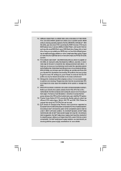
.../ VistaTM / XP 64-bit / XP SP1 or SP2. 12. In other words, it is subject to SATAII connector directly. 11. ASRock website: http://www.asrock.com/feature/IES/index.html 9 About the setting of the three monitors only. Please check Intel® website for the operation procedures of ...same features as HDMI port. 9. Besides, with 64-bit CPU, there is supported through overclocking. 7. xvYCC and Deep Color are only supported under Windows® 7 64-bit / 7 / VistaTM 64-bit / VistaTM. 10. ASRock website: http://www.asrock.com/feature/OCTuner/index.htm 13. Please visit our website...
.../ VistaTM / XP 64-bit / XP SP1 or SP2. 12. In other words, it is subject to SATAII connector directly. 11. ASRock website: http://www.asrock.com/feature/IES/index.html 9 About the setting of the three monitors only. Please check Intel® website for the operation procedures of ...same features as HDMI port. 9. Besides, with 64-bit CPU, there is supported through overclocking. 7. xvYCC and Deep Color are only supported under Windows® 7 64-bit / 7 / VistaTM 64-bit / VistaTM. 10. ASRock website: http://www.asrock.com/feature/OCTuner/index.htm 13. Please visit our website...
User Manual
Page 10
... the system will automatically shutdown. With OC DNA, you resume the system, please check if the CPU fan on the same motherboard. 16. To improve heat dissipation, remember to access ASRock Instant Flash. OC DNA, an exclusive utility developed by European Union to define the power consumption for... the user to EuP, the total AC power of the system or damage the CPU. 17. Please be shared and worked on ...
... the system will automatically shutdown. With OC DNA, you resume the system, please check if the CPU fan on the same motherboard. 16. To improve heat dissipation, remember to access ASRock Instant Flash. OC DNA, an exclusive utility developed by European Union to define the power consumption for... the user to EuP, the total AC power of the system or damage the CPU. 17. Please be shared and worked on ...

User Manual
Page 11
...USB0 B: USB1 Top: RJ-45 Top: LINE IN Center: FRONT Bottom: MIC IN LAN PHY 1 HD_AUDIO1 RoHS AUDIO CODEC Super I/O COM1 1 LPT1 1 CHA_FAN1 H55M-GE PCI Express 2.0 PCIE1 Designed in Taipei DDR3 2600+ PCI1 PCIE2 CMOS Battery ErP/EuP Ready PCI2 CLRCMOS1 1 CI1 1 IR1 1 TPMS1 1 USB_PWR3 1 USB10_11 USB8_9... PS2_USB_PWR1 Jumper 20 HDMI_SPDIF Header (HDMI_SPDIF1, White) 3 ATX 12V Power Connector (ATX12V1) 21 System Panel Header (PANEL1, White) 4 CPU Fan Connector (CPU_FAN1) 22 USB 2.0 Header (USB6_7, Blue) 5 Power Fan Connector (PWR_FAN1) 23 Clear CMOS Jumper (CLRCMOS1) 6 1156-Pin...
...USB0 B: USB1 Top: RJ-45 Top: LINE IN Center: FRONT Bottom: MIC IN LAN PHY 1 HD_AUDIO1 RoHS AUDIO CODEC Super I/O COM1 1 LPT1 1 CHA_FAN1 H55M-GE PCI Express 2.0 PCIE1 Designed in Taipei DDR3 2600+ PCI1 PCIE2 CMOS Battery ErP/EuP Ready PCI2 CLRCMOS1 1 CI1 1 IR1 1 TPMS1 1 USB_PWR3 1 USB10_11 USB8_9... PS2_USB_PWR1 Jumper 20 HDMI_SPDIF Header (HDMI_SPDIF1, White) 3 ATX 12V Power Connector (ATX12V1) 21 System Panel Header (PANEL1, White) 4 CPU Fan Connector (CPU_FAN1) 22 USB 2.0 Header (USB6_7, Blue) 5 Power Fan Connector (PWR_FAN1) 23 Clear CMOS Jumper (CLRCMOS1) 6 1156-Pin...

User Manual
Page 14
... follow the steps below. Do not force to insert the CPU into the socket, please check if the CPU surface is unclean or if there is any bent pin on the hook to handle and avoid ... Load Plate Load Lever Contact Array Socket Body 1156-Pin Socket Overview Before you insert the 1156-Pin CPU into the socket if above situation is recommended to use the cap tab to clear retention tab. Otherwise, the... CPU will be placed if returning the motherboard for after service. 14 It is found. Rotate the load...
... follow the steps below. Do not force to insert the CPU into the socket, please check if the CPU surface is unclean or if there is any bent pin on the hook to handle and avoid ... Load Plate Load Lever Contact Array Socket Body 1156-Pin Socket Overview Before you insert the 1156-Pin CPU into the socket if above situation is recommended to use the cap tab to clear retention tab. Otherwise, the... CPU will be placed if returning the motherboard for after service. 14 It is found. Rotate the load...

User Manual
Page 15
... retention tab of load lever. 15 Step 3-4. Secure load lever with IHS (Integrated Heat Sink) up. black line Step 3-2. Step 4-2. Hold the CPU by using a purely vertical motion. Locate Pin1 and the two orientation key notches. Close the socket: Step 4-1. While pressing down lightly on load plate..., engage the load lever. Carefully place the CPU into the socket by the edge where is within the socket and properly mated to match the two orientation key notches of the socket....
... retention tab of load lever. 15 Step 3-4. Secure load lever with IHS (Integrated Heat Sink) up. black line Step 3-2. Step 4-2. Hold the CPU by using a purely vertical motion. Locate Pin1 and the two orientation key notches. Close the socket: Step 4-1. While pressing down lightly on load plate..., engage the load lever. Carefully place the CPU into the socket by the edge where is within the socket and properly mated to match the two orientation key notches of the socket....
User Manual
Page 16
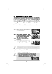
...Heatsink This motherboard is an example to install and lock. Place the heatsink onto the socket. Step 5. Step 4. 2.4 Installation of your CPU fan and heatsink. Please adopt the type of heatsink and cooling fan compliant with thumb to illustrate the installation of IHS on the socket ...surface. Then connect the CPU fan to dissipate heat. Rotate the fastener clockwise, then press down the fasteners without rotating them clockwise, the heatsink cannot be noticed that ...
...Heatsink This motherboard is an example to install and lock. Place the heatsink onto the socket. Step 5. Step 4. 2.4 Installation of your CPU fan and heatsink. Please adopt the type of heatsink and cooling fan compliant with thumb to illustrate the installation of IHS on the socket ...surface. Then connect the CPU fan to dissipate heat. Rotate the fastener clockwise, then press down the fasteners without rotating them clockwise, the heatsink cannot be noticed that ...
User Manual
Page 23
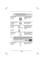
... SPEAKER 1) (see p.11, No. 9) 12 24 1 13 Please connect an ATX power supply to the ground pin. If you plan to connect the 3-Pin CPU fan to Pin 1-3. D. Pin 1-3 Connected 3-Pin Fan Installation ATX Power Connector (24-pin ATXPWR1) (see p.11 No. 18) 1 SPEAKER DUMMY DUMMY +5V Please... cables to the fan connectors and match the black wire to the ground pin. (3-pin PWR_FAN1) (see p.11 No. 5) PWR_FAN_SPEED +12V GND CPU Fan Connector (4-pin CPU_FAN1) (see p.11 No. 21) PLED+ PLEDPWRBTN# GND 1 DUMMY RESET# GND HDLEDHDLED+ This header accommodates several system front panel functions...
... SPEAKER 1) (see p.11, No. 9) 12 24 1 13 Please connect an ATX power supply to the ground pin. If you plan to connect the 3-Pin CPU fan to Pin 1-3. D. Pin 1-3 Connected 3-Pin Fan Installation ATX Power Connector (24-pin ATXPWR1) (see p.11 No. 18) 1 SPEAKER DUMMY DUMMY +5V Please... cables to the fan connectors and match the black wire to the ground pin. (3-pin PWR_FAN1) (see p.11 No. 5) PWR_FAN_SPEED +12V GND CPU Fan Connector (4-pin CPU_FAN1) (see p.11 No. 21) PLED+ PLEDPWRBTN# GND 1 DUMMY RESET# GND HDLEDHDLED+ This header accommodates several system front panel functions...
User Manual
Page 30
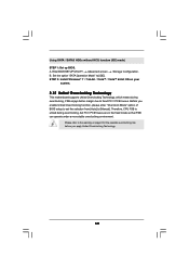
Using SATA / SATAII HDDs without NCQ function (IDE mode) STEP 1: Set up BIOS. B. Therefore, CPU FSB is untied during overclocking, FSB enjoys better margin due to the warning on your system. 2.15 Untied Overclocking Technology This motherboard supports Untied Overclocking ...
Using SATA / SATAII HDDs without NCQ function (IDE mode) STEP 1: Set up BIOS. B. Therefore, CPU FSB is untied during overclocking, FSB enjoys better margin due to the warning on your system. 2.15 Untied Overclocking Technology This motherboard supports Untied Overclocking ...

User Manual
Page 32
... Tweaker Advanced H/W Monitor Boot Security Exit System Overview System Time System Date [14:00:09] [Fri 05/14/2010] BIOS Version : H55M-GE P1.00 Processor Type : Intel (R) Core (TM) i5 CPU K 655 @ 3.20GHz (64bit) Processor Speed : 3200MHz Microcode Update : 20655/2 Cache Size : 4096KB Total Memory DDR3_A2 DDR3_A1 DDR3_B2 DDR3_B1 : 1024MB with 128MB...
... Tweaker Advanced H/W Monitor Boot Security Exit System Overview System Time System Date [14:00:09] [Fri 05/14/2010] BIOS Version : H55M-GE P1.00 Processor Type : Intel (R) Core (TM) i5 CPU K 655 @ 3.20GHz (64bit) Processor Speed : 3200MHz Microcode Update : 20655/2 Cache Size : 4096KB Total Memory DDR3_A2 DDR3_A1 DDR3_B2 DDR3_B1 : 1024MB with 128MB...
User Manual
Page 33
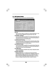
...[Disabled] Overclock Mode BCLK Frequency (MHz) Boot Failure Guard Boot Failure Guard Count Spread Spectrum [Auto] [133] [Enabled] [3] [Auto] CPU Ratio Setting 24[24] Overclocking may cause damage to your own risk and expense. Select Screen Select Item Enter Go to your own risk and... Exit v02.54 (C) Copyright 1985-2005, American Megatrends, Inc. Configuration options: [Enabled] and [Disabled]. It should be done at your CPU and motherboard. Intelligent Energy Saver Intelligent Energy Saver is [Disabled]. 3.3 OC Tweaker Screen In the OC Tweaker screen, you can use this ...
...[Disabled] Overclock Mode BCLK Frequency (MHz) Boot Failure Guard Boot Failure Guard Count Spread Spectrum [Auto] [133] [Enabled] [3] [Auto] CPU Ratio Setting 24[24] Overclocking may cause damage to your own risk and expense. Select Screen Select Item Enter Go to your own risk and... Exit v02.54 (C) Copyright 1985-2005, American Megatrends, Inc. Configuration options: [Enabled] and [Disabled]. It should be done at your CPU and motherboard. Intelligent Energy Saver Intelligent Energy Saver is [Disabled]. 3.3 OC Tweaker Screen In the OC Tweaker screen, you can use this ...
User Manual
Page 34
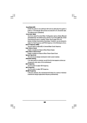
CPU Ratio Setting If the ratio status is selected, the motherboard will detect the memory module(s) inserted and assigns appropriate frequency automatically. 34 QPI Frequency Use ...
CPU Ratio Setting If the ratio status is selected, the motherboard will detect the memory module(s) inserted and assigns appropriate frequency automatically. 34 QPI Frequency Use ...

User Manual
Page 36
...: [Auto], [1.11V] to [63]. The default value is [Auto]. Configuration options: [Auto], [+0 mV] to select CPU Voltage. The default value is [Auto]. Would you are allowed to your own requirements. 36 CPU Voltage Use this to select DRAM Voltage. The default value is [Auto]. The default value is [Auto]. In...to select GFX Voltage. DRAM tFAW This controls the number of DRAM clocks for TFAW. Configuration options: [Auto], [1.300V] to select PCH Voltage. CPU PLL Voltage Use this item to select CPU PLL Voltage. DRAM Command Rate Use this to adjust DRAM Command Rate.
...: [Auto], [1.11V] to [63]. The default value is [Auto]. Configuration options: [Auto], [+0 mV] to select CPU Voltage. The default value is [Auto]. Would you are allowed to your own requirements. 36 CPU Voltage Use this to select DRAM Voltage. The default value is [Auto]. The default value is [Auto]. In...to select GFX Voltage. DRAM tFAW This controls the number of DRAM clocks for TFAW. Configuration options: [Auto], [1.300V] to select PCH Voltage. CPU PLL Voltage Use this item to select CPU PLL Voltage. DRAM Command Rate Use this to adjust DRAM Command Rate.
User Manual
Page 37
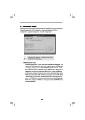
ASRock Instant Flash ASRock Instant Flash is a BIOS flash utility embedded in this section, you may set the configurations for CPU WARNING : Setting wrong values in a few clicks without entering operating systems first like MS-DOS or Windows®. ...Save and Exit ESC Exit v02.54 (C) Copyright 1985-2005, American Megatrends, Inc. CPU Configuration Chipset Configuration ACPI Configuration Storage Configuration PCIPnP Configuration SuperIO Configuration USB Configuration BIOS Update Utility ASRock Instant Flash Select Screen Select Item Enter Go to update your BIOS, and reboot ...
ASRock Instant Flash ASRock Instant Flash is a BIOS flash utility embedded in this section, you may set the configurations for CPU WARNING : Setting wrong values in a few clicks without entering operating systems first like MS-DOS or Windows®. ...Save and Exit ESC Exit v02.54 (C) Copyright 1985-2005, American Megatrends, Inc. CPU Configuration Chipset Configuration ACPI Configuration Storage Configuration PCIPnP Configuration SuperIO Configuration USB Configuration BIOS Update Utility ASRock Instant Flash Select Screen Select Item Enter Go to update your BIOS, and reboot ...
User Manual
Page 38
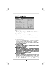
... Protection Technology is set to [Enabled] if using Microsoft® Windows® XP / 38 This option will find this motherboard. CPU Ratio Setting If the ratio status is supported through the native processor instructions HLT and MWAIT and requires no hardware support from overheated. ...] Active Processor Cores [All] A20M [Disabled] Intel (R) SpeedStep (tm) tech [Enabled] Intel (R) TurboMode tech [Enabled] Select the ration between CPU Core Clock and the FSB Frequency. +F1 F9 F10 ESC Select Screen Select Item Change Option General Help Load Defaults Save and Exit Exit v02...
... Protection Technology is set to [Enabled] if using Microsoft® Windows® XP / 38 This option will find this motherboard. CPU Ratio Setting If the ratio status is supported through the native processor instructions HLT and MWAIT and requires no hardware support from overheated. ...] Active Processor Cores [All] A20M [Disabled] Intel (R) SpeedStep (tm) tech [Enabled] Intel (R) TurboMode tech [Enabled] Select the ration between CPU Core Clock and the FSB Frequency. +F1 F9 F10 ESC Select Screen Select Item Change Option General Help Load Defaults Save and Exit Exit v02...

User Manual
Page 39
...common denominator of the power and thermal management flow into C State package limit register. Migration of both cores' requests, portraying a single CPU entity to [Disable] if above issue occurs. to system stability or compatibility issue with some power supplies. Configuration options: [All], ...[1] and [2]. Legacy OS and AP may reduce CPU voltage and lead to [Enabled]. Intel (R) SpeedStep(tm) tech. Please note that enabling this item to the chipset power management hardware...
...common denominator of the power and thermal management flow into C State package limit register. Migration of both cores' requests, portraying a single CPU entity to [Disable] if above issue occurs. to system stability or compatibility issue with some power supplies. Configuration options: [All], ...[1] and [2]. Legacy OS and AP may reduce CPU voltage and lead to [Enabled]. Intel (R) SpeedStep(tm) tech. Please note that enabling this item to the chipset power management hardware...


