User Manual
Page 6
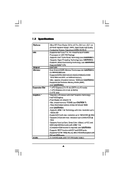
... with max. All Solid Capacitor design (100% Japan-made high-quality Conductive Polymer Capacitors) (H55M-GE R2.0) - Supports EM64T CPU - Max. Intel® HD Graphics - Max. resolution up to 1920x1200 @ 60Hz - 1.2 Specifications Platform CPU Chipset Memory Expansion Slot Graphics * Audio - Supports Intel® Turbo Boost Technology (see CAUTION 4) - 4 x DDR3 DIMM slots - Dual Channel...
... with max. All Solid Capacitor design (100% Japan-made high-quality Conductive Polymer Capacitors) (H55M-GE R2.0) - Supports EM64T CPU - Max. Intel® HD Graphics - Max. resolution up to 1920x1200 @ 60Hz - 1.2 Specifications Platform CPU Chipset Memory Expansion Slot Graphics * Audio - Supports Intel® Turbo Boost Technology (see CAUTION 4) - 4 x DDR3 DIMM slots - Dual Channel...
User Manual
Page 7
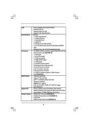
..., CPU GFX, VCCM, VTT, PCH PLL Voltage Multi-adjustment - Instant Boot - ASRock Instant Flash (see CAUTION 10) - 1 x IR header - 1 x Print Port header - 1 x COM port header - 1 x HDMI_SPDIF header - 1 x TPM header - 1 x Chassis Intrusion header - PCIE x1 Gigabit LAN 10/100/1000 Mb/s - HD Audio Jack: Line in/Front Speaker/Microphone - 6 x SATAII 3.0Gb/s connectors, support...
..., CPU GFX, VCCM, VTT, PCH PLL Voltage Multi-adjustment - Instant Boot - ASRock Instant Flash (see CAUTION 10) - 1 x IR header - 1 x Print Port header - 1 x COM port header - 1 x HDMI_SPDIF header - 1 x TPM header - 1 x Chassis Intrusion header - PCIE x1 Gigabit LAN 10/100/1000 Mb/s - HD Audio Jack: Line in/Front Speaker/Microphone - 6 x SATAII 3.0Gb/s connectors, support...

User Manual
Page 11
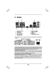
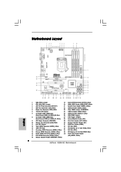
...T: USB2 B: USB3 USB 2.0 T: USB0 B: USB1 Top: RJ-45 Top: LINE IN Center: FRONT Bottom: MIC IN LAN PHY 1 HD_AUDIO1 RoHS AUDIO CODEC Super I/O COM1 1 LPT1 1 CHA_FAN1 H55M-GE PCI Express 2.0 PCIE1 Designed in Taipei DDR3 2600+ PCI1 PCIE2 CMOS Battery ErP/EuP Ready PCI2 CLRCMOS1 1 CI1 1 IR1 1 TPMS1 1 USB_PWR3 1 ...Primary SATAII Connector (SATAII_1, Blue) 35 PCI Express 2.0 x16 Slot (PCIE1, Blue) 16 Fourth SATAII Connector (SATAII_4, Blue) 36 Front Panel Audio Header 17 Fifth SATAII Connector (SATAII_5, Blue) (HD_AUDIO1, White) 18 Chassis Speaker Header (SPEAKER 1, White) 11
...T: USB2 B: USB3 USB 2.0 T: USB0 B: USB1 Top: RJ-45 Top: LINE IN Center: FRONT Bottom: MIC IN LAN PHY 1 HD_AUDIO1 RoHS AUDIO CODEC Super I/O COM1 1 LPT1 1 CHA_FAN1 H55M-GE PCI Express 2.0 PCIE1 Designed in Taipei DDR3 2600+ PCI1 PCIE2 CMOS Battery ErP/EuP Ready PCI2 CLRCMOS1 1 CI1 1 IR1 1 TPMS1 1 USB_PWR3 1 ...Primary SATAII Connector (SATAII_1, Blue) 35 PCI Express 2.0 x16 Slot (PCIE1, Blue) 16 Fourth SATAII Connector (SATAII_4, Blue) 36 Front Panel Audio Header 17 Fifth SATAII Connector (SATAII_5, Blue) (HD_AUDIO1, White) 18 Chassis Speaker Header (SPEAKER 1, White) 11
User Manual
Page 12
...Advanced Options" on the left side on your computer, you install. For Windows® XP / XP 64-bit OS: Please click "VIA HD Audio Deck" icon , and click "Speaker". LAN Port LED Indications Activity/Link LED SPEED LED Status Description Status Description ACT/LINK SPEED LED LED Off ... Green 1Gbps connection LAN Port To enable Multi-Streaming function, you are two LED next to the front panel audio header. Then you need to connect a front panel audio cable to the LAN port. After restarting your system. Please follow below for the LAN port LED indications.
...Advanced Options" on the left side on your computer, you install. For Windows® XP / XP 64-bit OS: Please click "VIA HD Audio Deck" icon , and click "Speaker". LAN Port LED Indications Activity/Link LED SPEED LED Status Description Status Description ACT/LINK SPEED LED LED Off ... Green 1Gbps connection LAN Port To enable Multi-Streaming function, you are two LED next to the front panel audio header. Then you need to connect a front panel audio cable to the LAN port. After restarting your system. Please follow below for the LAN port LED indications.
User Manual
Page 22
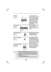
...SPD5 BUSY SPD4 PE SPD3 SLCT SPD2 SPD1 SPD0 STB# This is an interface for print port cable that allows convenient connection of audio devices. 1. Connect Mic_IN (MIC) to OUT2_L. 22 This motherboard supports CASE OPEN detection feature that allows convenient connection and control ... it to install your system. 2. Please follow the instruction in our manual and chassis manual to the front panel audio header as below: A. High Definition Audio supports Jack Sensing, but the panel wire on the chassis must support HDA to function correctly. Print Port Header (...
...SPD5 BUSY SPD4 PE SPD3 SLCT SPD2 SPD1 SPD0 STB# This is an interface for print port cable that allows convenient connection of audio devices. 1. Connect Mic_IN (MIC) to OUT2_L. 22 This motherboard supports CASE OPEN detection feature that allows convenient connection and control ... it to install your system. 2. Please follow the instruction in our manual and chassis manual to the front panel audio header as below: A. High Definition Audio supports Jack Sensing, but the panel wire on the chassis must support HDA to function correctly. Print Port Header (...
User Manual
Page 23
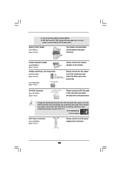
... the CPU fan connector on this motherboard, please connect it to Ground (GND). D. You don't need to connect them for HD audio panel only. MIC_RET and OUT_RET are for AC'97 audio panel. Chassis Speaker Header (4-pin SPEAKER 1) (see p.11, No. 9) 12 24 1 13 Please connect an ATX power supply to this...
... the CPU fan connector on this motherboard, please connect it to Ground (GND). D. You don't need to connect them for HD audio panel only. MIC_RET and OUT_RET are for AC'97 audio panel. Chassis Speaker Header (4-pin SPEAKER 1) (see p.11, No. 9) 12 24 1 13 Please connect an ATX power supply to this...
User Manual
Page 24
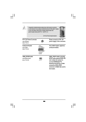
... power connector, 12 24 it can still work if you adopt a traditional 20-pin ATX power supply. Though this header. 24 HDMI_SPDIF header, providing SPDIF audio output to HDMI VGA card, allows the system to connect HDMI Digital TV/ projector/LCD devices.
... power connector, 12 24 it can still work if you adopt a traditional 20-pin ATX power supply. Though this header. 24 HDMI_SPDIF header, providing SPDIF audio output to HDMI VGA card, allows the system to connect HDMI Digital TV/ projector/LCD devices.
User Manual
Page 40
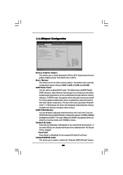
...FIXED Memory You are allowed to adjust the shared memory size in this option to enable or disable the "Onboard HDMI HD Audio" feature. 40 The default value is plugged. 3.4.2Chipset Configuration BIOS SETUP UTILITY Advanced Chipset Settings Primary Graphics Adapter Share Memory... DVMT Mode Select DVMT/FIXED Memory Onboard HD Audio Front Panel Onboard HDMI HD Audio OnBoard Lan [PCI] [Auto] [DVMT Mode] [Maximum DVMT] [Auto] [Auto] [Enabled] [Enabled] Intel VT-d ...
...FIXED Memory You are allowed to adjust the shared memory size in this option to enable or disable the "Onboard HDMI HD Audio" feature. 40 The default value is plugged. 3.4.2Chipset Configuration BIOS SETUP UTILITY Advanced Chipset Settings Primary Graphics Adapter Share Memory... DVMT Mode Select DVMT/FIXED Memory Onboard HD Audio Front Panel Onboard HDMI HD Audio OnBoard Lan [PCI] [Auto] [DVMT Mode] [Maximum DVMT] [Auto] [Auto] [Enabled] [Enabled] Intel VT-d ...
Quick Installation Guide
Page 2
... PCI Slot (PCI1) 15 Primary SATAII Connector (SATAII_1, Blue) 35 PCI Express 2.0 x16 Slot (PCIE1, Blue) 16 Fourth SATAII Connector (SATAII_4, Blue) 36 Front Panel Audio Header 17 Fifth SATAII Connector (SATAII_5, Blue) (HD_AUDIO1, White) 18 Chassis Speaker Header (SPEAKER 1, White) 2 ASRock H55M-GE Motherboard
... PCI Slot (PCI1) 15 Primary SATAII Connector (SATAII_1, Blue) 35 PCI Express 2.0 x16 Slot (PCIE1, Blue) 16 Fourth SATAII Connector (SATAII_4, Blue) 36 Front Panel Audio Header 17 Fifth SATAII Connector (SATAII_5, Blue) (HD_AUDIO1, White) 18 Chassis Speaker Header (SPEAKER 1, White) 2 ASRock H55M-GE Motherboard
Quick Installation Guide
Page 3
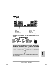
After restarting your change . 3 ASRock H55M-GE Motherboard English Then you install. In "Advanced Options" screen, select "Independent Headphone", and click "OK" to save your computer, you need to connect a front panel audio cable to the front panel audio header. LAN Port LED Indications ...10Mbps connection Blinking Data Activity Orange 100Mbps connection On Link Green 1Gbps connection LAN Port To enable Multi-Streaming function, you will find "VIA HD Audio Deck" tool on the bottom. I/O Panel 1 USB 2.0 Ports (USB45) 2 VGA/D-Sub Port 3 LAN RJ-45 Port 4 Line In ...
After restarting your change . 3 ASRock H55M-GE Motherboard English Then you install. In "Advanced Options" screen, select "Independent Headphone", and click "OK" to save your computer, you need to connect a front panel audio cable to the front panel audio header. LAN Port LED Indications ...10Mbps connection Blinking Data Activity Orange 100Mbps connection On Link Green 1Gbps connection LAN Port To enable Multi-Streaming function, you will find "VIA HD Audio Deck" tool on the bottom. I/O Panel 1 USB 2.0 Ports (USB45) 2 VGA/D-Sub Port 3 LAN RJ-45 Port 4 Line In ...

Quick Installation Guide
Page 5
... Profile (XMP) (see CAUTION 4) - 4 x DDR3 DIMM slots - Intel® HD Graphics - Supports HDMI 1.3a Technology with DVI and HDMI ports - 5.1 CH HD Audio (VIA® VT1705 Audio Codec) English 5 ASRock H55M-GE Motherboard resolution up to 1920x1200 - Supports DDR3 2600+(OC)/2133(OC)/1866(OC)/1600/ 1333/1066 non-ECC, un-buffered memory - Supports Full...
... Profile (XMP) (see CAUTION 4) - 4 x DDR3 DIMM slots - Intel® HD Graphics - Supports HDMI 1.3a Technology with DVI and HDMI ports - 5.1 CH HD Audio (VIA® VT1705 Audio Codec) English 5 ASRock H55M-GE Motherboard resolution up to 1920x1200 - Supports DDR3 2600+(OC)/2133(OC)/1866(OC)/1600/ 1333/1066 non-ECC, un-buffered memory - Supports Full...
Quick Installation Guide
Page 6
... 12V power connector - Drivers, Utilities, AntiVirus Software (Trial Version), ASRock Software Suite (CyberLink DVD Suite and Creative Sound Blaster X-Fi MB) (OEM and Trial Version) - HD Audio Jack: Line in/Front Speaker/Microphone - 6 x SATAII 3.0Gb/s... and Play" - ACPI 1.1 Compliance Wake Up Events - Realtek RTL8111E - SMBIOS 2.3.1 Support - Front panel audio connector - 3 x USB 2.0 headers (support 6 USB 2.0 ports) (see CAUTION 12) - ASRock Instant Flash (see CAUTION 14) English 6 ASRock H55M-GE Motherboard LAN Rear Panel I /O Panel - 1 x PS/2 Keyboard Port - 1 x VGA/D-Sub Port...
... 12V power connector - Drivers, Utilities, AntiVirus Software (Trial Version), ASRock Software Suite (CyberLink DVD Suite and Creative Sound Blaster X-Fi MB) (OEM and Trial Version) - HD Audio Jack: Line in/Front Speaker/Microphone - 6 x SATAII 3.0Gb/s... and Play" - ACPI 1.1 Compliance Wake Up Events - Realtek RTL8111E - SMBIOS 2.3.1 Support - Front panel audio connector - 3 x USB 2.0 headers (support 6 USB 2.0 ports) (see CAUTION 12) - ASRock Instant Flash (see CAUTION 14) English 6 ASRock H55M-GE Motherboard LAN Rear Panel I /O Panel - 1 x PS/2 Keyboard Port - 1 x VGA/D-Sub Port...

Quick Installation Guide
Page 18
.... This is an interface for front panel audio cable that detects if the chassis cover has been removed. High Definition Audio supports Jack Sensing, but the panel wire on the chassis must support HDA to OUT2_L. 18 ASRock H55M-GE Motherboard English This is an interface for print... port cable that allows convenient connection of audio devices. 1. Infrared Module Header (5-pin IR1...
.... This is an interface for front panel audio cable that detects if the chassis cover has been removed. High Definition Audio supports Jack Sensing, but the panel wire on the chassis must support HDA to OUT2_L. 18 ASRock H55M-GE Motherboard English This is an interface for print... port cable that allows convenient connection of audio devices. 1. Infrared Module Header (5-pin IR1...
Quick Installation Guide
Page 19
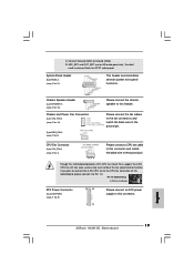
...cables to the fan connectors and match the black wire to Pin 1-3. D. MIC_RET and OUT_RET are for AC'97 audio panel. C. You don't need to connect them for HD audio panel only. If you plan to connect the 3-Pin CPU fan to the CPU fan connector on this header. ...provides 4-Pin CPU fan (Quiet Fan) support, the 3-Pin CPU fan still can work successfully even without the fan speed control function. English 19 ASRock H55M-GE Motherboard Connect Ground (GND) to the ground pin. CPU Fan Connector (4-pin CPU_FAN1) (see p.2 No. 21) This header accommodates several system front ...
...cables to the fan connectors and match the black wire to Pin 1-3. D. MIC_RET and OUT_RET are for AC'97 audio panel. C. You don't need to connect them for HD audio panel only. If you plan to connect the 3-Pin CPU fan to the CPU fan connector on this header. ...provides 4-Pin CPU fan (Quiet Fan) support, the 3-Pin CPU fan still can work successfully even without the fan speed control function. English 19 ASRock H55M-GE Motherboard Connect Ground (GND) to the ground pin. CPU Fan Connector (4-pin CPU_FAN1) (see p.2 No. 21) This header accommodates several system front ...

Quick Installation Guide
Page 20
Though this header. English 20 ASRock H55M-GE Motherboard To use the 20-pin ATX power supply, please plug your power supply along with Pin 1 and Pin 13. HDMI_SPDIF Header (2-pin HDMI_SPDIF1) (see p.2 ... header supports a serial port module. ATX 12V Power Connector (4-pin ATX12V1) (see p.2 No. 3) Serial port Header (9-pin COM1) (see p.2 No. 20) HDMI_SPDIF header, providing SPDIF audio output to HDMI VGA card, allows the system to this motherboard provides 24-pin ATX power connector, 12 24 it can still work if you...
Though this header. English 20 ASRock H55M-GE Motherboard To use the 20-pin ATX power supply, please plug your power supply along with Pin 1 and Pin 13. HDMI_SPDIF Header (2-pin HDMI_SPDIF1) (see p.2 ... header supports a serial port module. ATX 12V Power Connector (4-pin ATX12V1) (see p.2 No. 3) Serial port Header (9-pin COM1) (see p.2 No. 20) HDMI_SPDIF header, providing SPDIF audio output to HDMI VGA card, allows the system to this motherboard provides 24-pin ATX power connector, 12 24 it can still work if you...


