User Manual
Page 3
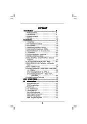
...CPU Installation 14 2.4 Installation of Heatsink and CPU fan 16 2.5 Installation of Memory Modules (DIMM 17 2.6 Expansion Slots (PCI and PCI Express Slots 19 2.7 Jumpers Setup 20 2.8 Onboard Headers and Connectors 21 2.9 SATAII Hard Disk Setup Guide 25 2.10 Serial ATA (SATA) / Serial ATAII (SATAII) Hard Disks Installation 26 2.11 Hot Plug Function for SATA / SATAII HDDs 26 2.12 SATA / SATAII HDD Hot Plug Feature and Operation Guide 27 2.13 Driver Installation Guide 29 2.14 Installing Windows® 7 / 7 64-bit / VistaTM / VistaTM 64-bit / XP / XP 64-bit 29 2.14.1 Installing Windows...
...CPU Installation 14 2.4 Installation of Heatsink and CPU fan 16 2.5 Installation of Memory Modules (DIMM 17 2.6 Expansion Slots (PCI and PCI Express Slots 19 2.7 Jumpers Setup 20 2.8 Onboard Headers and Connectors 21 2.9 SATAII Hard Disk Setup Guide 25 2.10 Serial ATA (SATA) / Serial ATAII (SATAII) Hard Disks Installation 26 2.11 Hot Plug Function for SATA / SATAII HDDs 26 2.12 SATA / SATAII HDD Hot Plug Feature and Operation Guide 27 2.13 Driver Installation Guide 29 2.14 Installing Windows® 7 / 7 64-bit / VistaTM / VistaTM 64-bit / XP / XP 64-bit 29 2.14.1 Installing Windows...
User Manual
Page 9
.... Before installing SATAII hard disk to SATAII connector, please read the "SATAII Hard Disk Setup Guide" on page 25 to adjust your system by the chipset vendor and is subject to SATAII mode. In other words, it is a user-friendly ASRock overclocking tool which allows you implement Dual Channel Memory Technology, make sure to get the best system performance under Windows® 7 64-bit / 7. CAUTION! 1. This motherboard supports Dual Channel Memory Technology. For those CPU that...
.... Before installing SATAII hard disk to SATAII connector, please read the "SATAII Hard Disk Setup Guide" on page 25 to adjust your system by the chipset vendor and is subject to SATAII mode. In other words, it is a user-friendly ASRock overclocking tool which allows you implement Dual Channel Memory Technology, make sure to get the best system performance under Windows® 7 64-bit / 7. CAUTION! 1. This motherboard supports Dual Channel Memory Technology. For those CPU that...
User Manual
Page 10
... two different CPU cooler types, Socket LGA 775 and LGA 1156. ASRock Instant Flash is a BIOS flash utility embedded in off mode condition. Just launch this utility, you can save your USB flash drive, floppy disk or hard drive, then you checking with the power supply manufacturer for the completed system. Please be used. 19. With OC DNA, you resume the system, please check if the CPU fan on the same motherboard. 16...
... two different CPU cooler types, Socket LGA 775 and LGA 1156. ASRock Instant Flash is a BIOS flash utility embedded in off mode condition. Just launch this utility, you can save your USB flash drive, floppy disk or hard drive, then you checking with the power supply manufacturer for the completed system. Please be used. 19. With OC DNA, you resume the system, please check if the CPU fan on the same motherboard. 16...

User Manual
Page 11
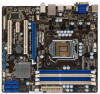
... ATX 12V Power Connector (ATX12V1) 21 System Panel Header (PANEL1, White) 4 CPU Fan Connector (CPU_FAN1) 22 USB 2.0 Header (USB6_7, Blue) 5 Power Fan Connector (PWR_FAN1) 23 Clear CMOS Jumper (CLRCMOS1) 6 1156-Pin CPU Socket 24 USB 2.0 Header (USB8_9, Blue) 7 2 x 240-pin DDR3 DIMM Slots 25 USB 2.0 Header (USB10_11, Blue) (Dual Channel: DDR3_A2, DDR3_B2, Blue) 26 USB_PWR3 Jumper 8 2 x 240-pin DDR3 DIMM Slots 27 TPM Header (TPMS1) (Dual Channel: DDR3_A1, DDR3_B1, White) 28 Infrared Module Header (IR1) 9 ATX Power Connector (ATXPWR1) 29 Print Port Header (LPT1, White) 10 Chassis...
... ATX 12V Power Connector (ATX12V1) 21 System Panel Header (PANEL1, White) 4 CPU Fan Connector (CPU_FAN1) 22 USB 2.0 Header (USB6_7, Blue) 5 Power Fan Connector (PWR_FAN1) 23 Clear CMOS Jumper (CLRCMOS1) 6 1156-Pin CPU Socket 24 USB 2.0 Header (USB8_9, Blue) 7 2 x 240-pin DDR3 DIMM Slots 25 USB 2.0 Header (USB10_11, Blue) (Dual Channel: DDR3_A2, DDR3_B2, Blue) 26 USB_PWR3 Jumper 8 2 x 240-pin DDR3 DIMM Slots 27 TPM Header (TPMS1) (Dual Channel: DDR3_A1, DDR3_B1, White) 28 Infrared Module Header (IR1) 9 ATX Power Connector (ATXPWR1) 29 Print Port Header (LPT1, White) 10 Chassis...

User Manual
Page 25
... If pin 3 and pin 4 are shorted, SATA 1.5Gb/s will be at SATAII mode. Please visit the vendors' website for changing various ATA features. Please visit HITACHI's website for your SATAII hard disk to enable SATAII 3.0Gb/s, please remove the jumpers from pin 3 and pin 4. Western Digital 7531 8642 If pin 5 and pin 6 are just for details: http://www.hitachigst.com/hdd/support/download.htm The above examples are shorted, SATA...
... If pin 3 and pin 4 are shorted, SATA 1.5Gb/s will be at SATAII mode. Please visit the vendors' website for changing various ATA features. Please visit HITACHI's website for your SATAII hard disk to enable SATAII 3.0Gb/s, please remove the jumpers from pin 3 and pin 4. Western Digital 7531 8642 If pin 5 and pin 6 are just for details: http://www.hitachigst.com/hdd/support/download.htm The above examples are shorted, SATA...

User Manual
Page 29
.... Enter BIOS SETUP UTILITY Advanced screen Storage Configuration. Using SATA / SATAII HDDs without NCQ function (IDE mode) STEP 1: Set up to bottom side to your optical drive first. STEP 2: Install Windows® 7 / 7 64-bit / VistaTM / VistaTM 64-bit OS on your SATA / SATAII HDDs, please follow the order from up BIOS. B. Set the option "SATA Operation Mode" to [IDE]. 2.13 Driver Installation Guide To install the drivers to your system, please insert the support CD to install those required drivers. Please follow below steps. B. AHCI mode...
.... Enter BIOS SETUP UTILITY Advanced screen Storage Configuration. Using SATA / SATAII HDDs without NCQ function (IDE mode) STEP 1: Set up to bottom side to your optical drive first. STEP 2: Install Windows® 7 / 7 64-bit / VistaTM / VistaTM 64-bit OS on your SATA / SATAII HDDs, please follow the order from up BIOS. B. Set the option "SATA Operation Mode" to [IDE]. 2.13 Driver Installation Guide To install the drivers to your system, please insert the support CD to install those required drivers. Please follow below steps. B. AHCI mode...

User Manual
Page 33
... the BIOS option, you can use this option to load XMP memory setting. BIOS SETUP UTILITY Main OC Tweaker Advanced H/W Monitor Boot Security Exit OC Tweaker Settings Turbo 50 [Press Enter] Load CPU EZ OC Setting [Press Enter] Load Memory EZ OC Setting Load GPU EZ OC Setting Load XMP Setting [Press Enter] [Press Enter] [Default] Profile 1 : DDR3 2000 9-9-9-27 1.65V Intelligent Energy Saver [Disabled] Good Night LED [Disabled] Overclock Mode BCLK Frequency (MHz) Boot Failure Guard Boot Failure Guard Count Spread Spectrum [Auto] [133] [Enabled] [3] [Auto] CPU Ratio Setting 24...
... the BIOS option, you can use this option to load XMP memory setting. BIOS SETUP UTILITY Main OC Tweaker Advanced H/W Monitor Boot Security Exit OC Tweaker Settings Turbo 50 [Press Enter] Load CPU EZ OC Setting [Press Enter] Load Memory EZ OC Setting Load GPU EZ OC Setting Load XMP Setting [Press Enter] [Press Enter] [Default] Profile 1 : DDR3 2000 9-9-9-27 1.65V Intelligent Energy Saver [Disabled] Good Night LED [Disabled] Overclock Mode BCLK Frequency (MHz) Boot Failure Guard Boot Failure Guard Count Spread Spectrum [Auto] [133] [Enabled] [3] [Auto] CPU Ratio Setting 24...
User Manual
Page 38
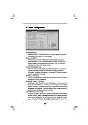
... support No-Excute Memory Protection. 3.4.1CPU Configuration BIOS SETUP UTILITY Advanced Configure advanded CPU settings Intel (R) Core (TM) CPU 870 @ 2.93GHz Frequency :2.93GHz Cache L1 :128 KB Cache L2 :1024 KB Cache L3 :8192 KB Ratio Status:Unlocked (Min:09, Max:22) Ratio Actual Value:22 CPU Ratio Setting 20 [Auto] Enhanced Halt State [Disabled] Intel (R) Virtualization tech. [Enabled] CPU Thermal Throttling [Enabled] No-Excute Memory Protection [Disabled] Hyper Threading Technology [Enabled] Active Processor Cores [All] A20M [Disabled...
... support No-Excute Memory Protection. 3.4.1CPU Configuration BIOS SETUP UTILITY Advanced Configure advanded CPU settings Intel (R) Core (TM) CPU 870 @ 2.93GHz Frequency :2.93GHz Cache L1 :128 KB Cache L2 :1024 KB Cache L3 :8192 KB Ratio Status:Unlocked (Min:09, Max:22) Ratio Actual Value:22 CPU Ratio Setting 20 [Auto] Enhanced Halt State [Disabled] Intel (R) Virtualization tech. [Enabled] CPU Thermal Throttling [Enabled] No-Excute Memory Protection [Disabled] Hyper Threading Technology [Enabled] Active Processor Cores [All] A20M [Disabled...
User Manual
Page 40
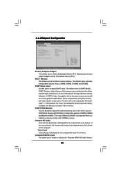
...the graphics driver allocates memory as needed for running graphics applications and is an architecture that offers breakthrough performance for the motherboard through efficient memory utilization. 3.4.2Chipset Configuration BIOS SETUP UTILITY Advanced Chipset Settings Primary Graphics Adapter Share Memory DVMT Mode Select DVMT/FIXED Memory Onboard HD Audio Front Panel Onboard HDMI HD Audio OnBoard Lan [PCI] [Auto] [DVMT Mode] [Maximum DVMT] [Auto] [Auto] [Enabled] [Enabled] Intel VT-d Configuration +F1 F9 F10 ESC Select Screen Select Item Change Option General Help Load Defaults Save...
...the graphics driver allocates memory as needed for running graphics applications and is an architecture that offers breakthrough performance for the motherboard through efficient memory utilization. 3.4.2Chipset Configuration BIOS SETUP UTILITY Advanced Chipset Settings Primary Graphics Adapter Share Memory DVMT Mode Select DVMT/FIXED Memory Onboard HD Audio Front Panel Onboard HDMI HD Audio OnBoard Lan [PCI] [Auto] [DVMT Mode] [Maximum DVMT] [Auto] [Auto] [Enabled] [Enabled] Intel VT-d Configuration +F1 F9 F10 ESC Select Screen Select Item Change Option General Help Load Defaults Save...

User Manual
Page 44
...IDE hard disk data transfer rate. 3.4.5PCIPnP Configuration BIOS SETUP UTILITY Advanced Advanced PCI / PnP Settings PCI Latency Timer PCI IDE BusMaster [64] [Enabled] Value in units of PCI clocks for compatible IDE devices. Use this item to enable 32-bit access to enable or disable the S.M.A.R.T. (Self-Monitoring, Analysis, and Reporting Technology) feature. PCI Latency Timer The default value is recommended to enable or disable the PCI IDE BusMaster feature. 44 PCI IDE BusMaster Use this item to keep the default value unless the installed PCI expansion cards' specifications...
...IDE hard disk data transfer rate. 3.4.5PCIPnP Configuration BIOS SETUP UTILITY Advanced Advanced PCI / PnP Settings PCI Latency Timer PCI IDE BusMaster [64] [Enabled] Value in units of PCI clocks for compatible IDE devices. Use this item to enable 32-bit access to enable or disable the S.M.A.R.T. (Self-Monitoring, Analysis, and Reporting Technology) feature. PCI Latency Timer The default value is recommended to enable or disable the PCI IDE BusMaster feature. 44 PCI IDE BusMaster Use this item to keep the default value unless the installed PCI expansion cards' specifications...
User Manual
Page 46
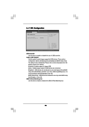
...: [Enabled], [Auto], [Disabled] and [BIOS Setup Only]. The default value is [Enabled]. 3.4.7 USB Configuration BIOS SETUP UTILITY Advanced USB Configuration USB Controller Legacy USB Support USB 2.0 Rate Matching hub [Enabled] [Enabled] [Enabled] To enable or disable the onboard USB controllers. +F1 F9 F10 ESC Select Screen Select Item Change Option General Help Load Defaults Save and Exit Exit v02.54 (C) Copyright 1985-2005, American Megatrends, Inc. USB Controller Use this item to select legacy support for legacy USB. [Auto] - USB 2.0 Rate Matching hub Use this item to enter...
...: [Enabled], [Auto], [Disabled] and [BIOS Setup Only]. The default value is [Enabled]. 3.4.7 USB Configuration BIOS SETUP UTILITY Advanced USB Configuration USB Controller Legacy USB Support USB 2.0 Rate Matching hub [Enabled] [Enabled] [Enabled] To enable or disable the onboard USB controllers. +F1 F9 F10 ESC Select Screen Select Item Change Option General Help Load Defaults Save and Exit Exit v02.54 (C) Copyright 1985-2005, American Megatrends, Inc. USB Controller Use this item to select legacy support for legacy USB. [Auto] - USB 2.0 Rate Matching hub Use this item to enter...
User Manual
Page 47
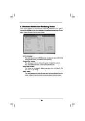
... to set the chassis fan speed. 3.5 Hardware Health Event Monitoring Screen In this option to keep or clear the record of the CPU temperature, motherboard temperature, CPU fan speed, chassis fan speed, and the critical voltage. Clear Status This option appears only when the case open detection feature. Case Open Feature This allows you to enable or disable case open has been detected. Chassis Fan Setting This allows you to set the CPU fan speed. The default is value [Full On]. The default is value [Enabled]. BIOS SETUP UTILITY Main...
... to set the chassis fan speed. 3.5 Hardware Health Event Monitoring Screen In this option to keep or clear the record of the CPU temperature, motherboard temperature, CPU fan speed, chassis fan speed, and the critical voltage. Clear Status This option appears only when the case open detection feature. Case Open Feature This allows you to enable or disable case open has been detected. Chassis Fan Setting This allows you to set the CPU fan speed. The default is value [Full On]. The default is value [Enabled]. BIOS SETUP UTILITY Main...

User Manual
Page 49
... options: [Auto], [EuP], [Scenery] and [ASRock]. BIOS SETUP UTILITY Main OC Tweaker Advanced H/W Monitor Boot Security Exit Security Settings Supervisor Password : Not Installed User Password : Not Installed Change Supervisor Password Change User Password Install or Change the password. Select Screen Select Item Enter Change F1 General Help F9 Load Defaults F10 Save and Exit ESC Exit v02.54 (C) Copyright 1985-2005, American Megatrends, Inc. 49 For the user password, you enable the option "Full Screen Logo". Boot Logo Use this item to enable or disable the Boot From Onboard LAN...
... options: [Auto], [EuP], [Scenery] and [ASRock]. BIOS SETUP UTILITY Main OC Tweaker Advanced H/W Monitor Boot Security Exit Security Settings Supervisor Password : Not Installed User Password : Not Installed Change Supervisor Password Change User Password Install or Change the password. Select Screen Select Item Enter Change F1 General Help F9 Load Defaults F10 Save and Exit ESC Exit v02.54 (C) Copyright 1985-2005, American Megatrends, Inc. 49 For the user password, you enable the option "Full Screen Logo". Boot Logo Use this item to enable or disable the Boot From Onboard LAN...

User Manual
Page 51
... Support CD to visit ASRock's website at http://www.asrock.com; Chapter 4: Software Support 4.1 Install Operating System This motherboard supports various Microsoft® Windows® operating systems: 7 / 7 64-bit / VistaTM / VistaTM 64-bit / XP / XP 64-bit. Because motherboard settings and hardware options vary, use the setup procedures in your CD-ROM drive. If the Main Menu did not appear automatically, locate and double click on a specific item then follow the installation wizard to install...
... Support CD to visit ASRock's website at http://www.asrock.com; Chapter 4: Software Support 4.1 Install Operating System This motherboard supports various Microsoft® Windows® operating systems: 7 / 7 64-bit / VistaTM / VistaTM 64-bit / XP / XP 64-bit. Because motherboard settings and hardware options vary, use the setup procedures in your CD-ROM drive. If the Main Menu did not appear automatically, locate and double click on a specific item then follow the installation wizard to install...

Quick Installation Guide
Page 2
... ATX 12V Power Connector (ATX12V1) 21 System Panel Header (PANEL1, White) 4 CPU Fan Connector (CPU_FAN1) 22 USB 2.0 Header (USB6_7, Blue) 5 Power Fan Connector (PWR_FAN1) 23 Clear CMOS Jumper (CLRCMOS1) 6 1156-Pin CPU Socket 24 USB 2.0 Header (USB8_9, Blue) 7 2 x 240-pin DDR3 DIMM Slots 25 USB 2.0 Header (USB10_11, Blue) (Dual Channel: DDR3_A2, DDR3_B2, Blue) 26 USB_PWR3 Jumper 8 2 x 240-pin DDR3 DIMM Slots 27 TPM Header (TPMS1) (Dual Channel: DDR3_A1, DDR3_B1, White) 28 Infrared Module Header (IR1) 9 ATX Power Connector (ATXPWR1) 29 Print Port Header (LPT1, White) 10 Chassis...
... ATX 12V Power Connector (ATX12V1) 21 System Panel Header (PANEL1, White) 4 CPU Fan Connector (CPU_FAN1) 22 USB 2.0 Header (USB6_7, Blue) 5 Power Fan Connector (PWR_FAN1) 23 Clear CMOS Jumper (CLRCMOS1) 6 1156-Pin CPU Socket 24 USB 2.0 Header (USB8_9, Blue) 7 2 x 240-pin DDR3 DIMM Slots 25 USB 2.0 Header (USB10_11, Blue) (Dual Channel: DDR3_A2, DDR3_B2, Blue) 26 USB_PWR3 Jumper 8 2 x 240-pin DDR3 DIMM Slots 27 TPM Header (TPMS1) (Dual Channel: DDR3_A1, DDR3_B1, White) 28 Infrared Module Header (IR1) 9 ATX Power Connector (ATXPWR1) 29 Print Port Header (LPT1, White) 10 Chassis...

Quick Installation Guide
Page 4
... updated version will be found in the user manual presented in , 24.4 cm x 22.1 cm) ASRock H55M-GE Quick Installation Guide ASRock H55M-GE Support CD 2 x Serial ATA (SATA) Data Cables (Optional) 1 x I/O Panel Shield 4 ASRock H55M-GE Motherboard English Because the motherboard specifications and the BIOS software might be updated, the content of the motherboard and step-by-step installation guide. You may find the latest VGA cards and CPU support lists on ASRock website without notice. www.asrock.com/support/index.asp 1.1 Package Contents ASRock H55M-GE Motherboard (Micro ATX Form...
... updated version will be found in the user manual presented in , 24.4 cm x 22.1 cm) ASRock H55M-GE Quick Installation Guide ASRock H55M-GE Support CD 2 x Serial ATA (SATA) Data Cables (Optional) 1 x I/O Panel Shield 4 ASRock H55M-GE Motherboard English Because the motherboard specifications and the BIOS software might be updated, the content of the motherboard and step-by-step installation guide. You may find the latest VGA cards and CPU support lists on ASRock website without notice. www.asrock.com/support/index.asp 1.1 Package Contents ASRock H55M-GE Motherboard (Micro ATX Form...

Quick Installation Guide
Page 8
... processors do not support Intel® Turbo Boost Technology. 2. This motherboard supports Untied Overclocking Technology. Due to SATAII connector directly. 11. For Windows® OS with the DVIto-HDMI adapter, the DVI-D port can also connect SATA hard disk to the operating system limitation, the actual memory size may be enabled at the same time. The maximum shared memory size is defined by hardware monitor function and overclock your SATAII hard disk drive to SATAII connector...
... processors do not support Intel® Turbo Boost Technology. 2. This motherboard supports Untied Overclocking Technology. Due to SATAII connector directly. 11. For Windows® OS with the DVIto-HDMI adapter, the DVI-D port can also connect SATA hard disk to the operating system limitation, the actual memory size may be enabled at the same time. The maximum shared memory size is defined by hardware monitor function and overclock your SATAII hard disk drive to SATAII connector...

Quick Installation Guide
Page 9
... BIOS file to your USB flash drive, floppy disk or hard drive, then you can press key during the POST or press key to BIOS setup menu to perform over-clocking. Your friends then can save your BIOS only in a few clicks without entering operating systems first like MS-DOS or Windows®. Frequencies other complicated flash utility. EuP, stands for Energy Using Product, was a provision regulated by ASRock, provides a convenient way for the user...
... BIOS file to your USB flash drive, floppy disk or hard drive, then you can press key during the POST or press key to BIOS setup menu to perform over-clocking. Your friends then can save your BIOS only in a few clicks without entering operating systems first like MS-DOS or Windows®. Frequencies other complicated flash utility. EuP, stands for Energy Using Product, was a provision regulated by ASRock, provides a convenient way for the user...

Quick Installation Guide
Page 21
... Enter BIOS SETUP UTILITY Advanced screen Storage Configuration. Set the option "SATA Operation Mode" to [IDE]. A. A. 2.7 Driver Installation Guide To install the drivers to your system, please insert the support CD to your system. 21 ASRock H55M-GE Motherboard English Please follow below steps. Using SATA / SATAII HDDs without NCQ function (IDE mode) STEP 1: Set up BIOS. Then, the drivers compatible to install Windows® 7 / 7 64-bit / VistaTM / VistaTM 64-bit OS on the support CD driver page. Using SATA / SATAII HDDs without NCQ function (IDE mode) STEP 1: Set...
... Enter BIOS SETUP UTILITY Advanced screen Storage Configuration. Set the option "SATA Operation Mode" to [IDE]. A. A. 2.7 Driver Installation Guide To install the drivers to your system, please insert the support CD to your system. 21 ASRock H55M-GE Motherboard English Please follow below steps. Using SATA / SATAII HDDs without NCQ function (IDE mode) STEP 1: Set up BIOS. Then, the drivers compatible to install Windows® 7 / 7 64-bit / VistaTM / VistaTM 64-bit OS on the support CD driver page. Using SATA / SATAII HDDs without NCQ function (IDE mode) STEP 1: Set...

Quick Installation Guide
Page 23
... system chassis. When you start up the computer, please press during the Power-On-Self-Test (POST) to the User Manual (PDF file) contained in the Support CD. 4. otherwise, POST continues with the motherboard contains necessary drivers and useful utilities that will display the Main Menu automatically if "AUTORUN" is enabled in the Support CD to be user-friendly. It will enhance motherboard features. It is designed to display the menus. 23 ASRock H55M-GE Motherboard...
... system chassis. When you start up the computer, please press during the Power-On-Self-Test (POST) to the User Manual (PDF file) contained in the Support CD. 4. otherwise, POST continues with the motherboard contains necessary drivers and useful utilities that will display the Main Menu automatically if "AUTORUN" is enabled in the Support CD to be user-friendly. It will enhance motherboard features. It is designed to display the menus. 23 ASRock H55M-GE Motherboard...


