
Intel Rapid Storage Guide
Page 12
... system BIOS. 1. Click the Storage Configuration menu. 4. Switch the SATA Operation Mode option to enable RAID in System BIOS Use the instructions included with your motherboard to RAID. 5. Select 1: Create RAID Volume and press Enter. 3. Enetr the Advanced menu. 3. Select the appropriate number of hard drives and press Space to select...
... system BIOS. 1. Click the Storage Configuration menu. 4. Switch the SATA Operation Mode option to enable RAID in System BIOS Use the instructions included with your motherboard to RAID. 5. Select 1: Create RAID Volume and press Enter. 3. Enetr the Advanced menu. 3. Select the appropriate number of hard drives and press Space to select...

RAID Installation Guide
Page 2
Guide to create RAID on this guide carefully according to the Intel southbridge chipset that your motherboard adopts. You may install SATA hard disks on SATA ports. 2 1. This section will guide you how to SATA Hard Disks Installation 1.1 Serial ATA (SATA) Hard Disks Installation Intel chipset supports Serial ATA (SATA) hard disks with RAID functions, including RAID 0, RAID 1, RAID 5, RAID 10 and Intel Rapid Storage. Please read the RAID configurations in this motherboard for internal storage devices.
Guide to create RAID on this guide carefully according to the Intel southbridge chipset that your motherboard adopts. You may install SATA hard disks on SATA ports. 2 1. This section will guide you how to SATA Hard Disks Installation 1.1 Serial ATA (SATA) Hard Disks Installation Intel chipset supports Serial ATA (SATA) hard disks with RAID functions, including RAID 0, RAID 1, RAID 5, RAID 10 and Intel Rapid Storage. Please read the RAID configurations in this motherboard for internal storage devices.

RAID Installation Guide
Page 3
.... RAID 0 (Data Striping) RAID 0 is a method combining two or more hard disk drives into one drive fails. 3 Guide to RAID Configurations 2.1 Introduction of RAID This motherboard adopts Intel southbridge chipset that copies and maintains an identical image of the same model and capacity when creating a RAID set. For optimal performance, please...
.... RAID 0 (Data Striping) RAID 0 is a method combining two or more hard disk drives into one drive fails. 3 Guide to RAID Configurations 2.1 Introduction of RAID This motherboard adopts Intel southbridge chipset that copies and maintains an identical image of the same model and capacity when creating a RAID set. For optimal performance, please...

RAID Installation Guide
Page 23
STEP 1: Copy Intel® RAID drivers into a USB flash disk You can download the drivers from ASRock's website and unzip the files into a USB flash disk or copy the files from ASRock's motherboard support CD. (Please copy the files under the following directory: 32 bit: ..\i386\Win7_Intel.. 64-bit: ..\AMD64\Win7-64_Intel.. STEP 2: Install...
STEP 1: Copy Intel® RAID drivers into a USB flash disk You can download the drivers from ASRock's website and unzip the files into a USB flash disk or copy the files from ASRock's motherboard support CD. (Please copy the files under the following directory: 32 bit: ..\i386\Win7_Intel.. 64-bit: ..\AMD64\Win7-64_Intel.. STEP 2: Install...

RAID Installation Guide
Page 25
... Windows® or install driver/utilities. Please request the hotfix KB2505454 through this problem. Windows® will need to follow the instructions below to install motherboard drivers and utilities. 25 If you will install this hotfix then reboot by itself. Reboot your system. (It may take a long time; >30 mins.) C. Windows...
... Windows® or install driver/utilities. Please request the hotfix KB2505454 through this problem. Windows® will need to follow the instructions below to install motherboard drivers and utilities. 25 If you will install this hotfix then reboot by itself. Reboot your system. (It may take a long time; >30 mins.) C. Windows...

User Manual
Page 2
..., and are furnished for loss of profits, loss of business, loss of data, interruption of business and the like), even if ASRock has been advised of the possibility of documentation by the purchaser for backup purpose, without notice, and should not be liable for any... by any means, except duplication of such damages arising from any errors or omissions that may not cause harmful interference, and (2) this motherboard contains Perchlorate, a toxic substance controlled in this documentation. With respect to the contents of this documentation are used only for identification or...
..., and are furnished for loss of profits, loss of business, loss of data, interruption of business and the like), even if ASRock has been advised of the possibility of documentation by the purchaser for backup purpose, without notice, and should not be liable for any... by any means, except duplication of such damages arising from any errors or omissions that may not cause harmful interference, and (2) this motherboard contains Perchlorate, a toxic substance controlled in this documentation. With respect to the contents of this documentation are used only for identification or...

User Manual
Page 4
Contents Chapter 1 Introduction 1 1.1 Package Contents 1 1.2 Specifications 2 1.3 Motherboard Layout 7 1.4 I/O Panel 9 Chapter 2 Installation 10 2.1 Installing the CPU 11 2.2 Installing the CPU Fan and Heatsink 14 2.3 Installing Memory Modules (DIMM) 15 2.4 Expansion Slots (PCI Express ...
Contents Chapter 1 Introduction 1 1.1 Package Contents 1 1.2 Specifications 2 1.3 Motherboard Layout 7 1.4 I/O Panel 9 Chapter 2 Installation 10 2.1 Installing the CPU 11 2.2 Installing the CPU Fan and Heatsink 14 2.3 Installing Memory Modules (DIMM) 15 2.4 Expansion Slots (PCI Express ...

User Manual
Page 5
3.2 ASRock Motherboard Utility (Phantom Gaming Tuning) 40 3.3 ASRock Live Update & APP Shop 43 3.3.1 UI Overview 43 3.3.2 Apps 44 3.3.3 BIOS & Drivers 47 3.3.4 Setting 48 3.4 Nahimic Audio 49 3.5 ASRock Polychrome SYNC 50 Chapter 4 UEFI SETUP UTILITY 53 4.1 Introduction 53 4.2 EZ Mode 54 4.3 Advanced Mode 55 4.3.1 UEFI Menu Bar 55 4.3.2 Navigation Keys 56 4.4 Main Screen ...
3.2 ASRock Motherboard Utility (Phantom Gaming Tuning) 40 3.3 ASRock Live Update & APP Shop 43 3.3.1 UI Overview 43 3.3.2 Apps 44 3.3.3 BIOS & Drivers 47 3.3.4 Setting 48 3.4 Nahimic Audio 49 3.5 ASRock Polychrome SYNC 50 Chapter 4 UEFI SETUP UTILITY 53 4.1 Introduction 53 4.2 EZ Mode 54 4.3 Advanced Mode 55 4.3.1 UEFI Menu Bar 55 4.3.2 Navigation Keys 56 4.4 Main Screen ...
User Manual
Page 7
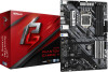
... excellent performance with robust design conforming to ASRock's commitment to change without further notice. ASRock website http://www.asrock.com. 1.1 Package Contents • ASRock H470 Phantom Gaming 4 Motherboard (ATX Form Factor) • ASRock H470 Phantom Gaming 4 Quick Installation Guide • ASRock H470 Phantom Gaming 4 Support CD • 2 x Serial ATA (SATA) Data Cables (Optional) • 3 x Screws for purchasing ASRock H470 Phantom Gaming 4 motherboard, a reliable motherboard produced under ASRock's consistently stringent quality control. You may...
... excellent performance with robust design conforming to ASRock's commitment to change without further notice. ASRock website http://www.asrock.com. 1.1 Package Contents • ASRock H470 Phantom Gaming 4 Motherboard (ATX Form Factor) • ASRock H470 Phantom Gaming 4 Quick Installation Guide • ASRock H470 Phantom Gaming 4 Support CD • 2 x Serial ATA (SATA) Data Cables (Optional) • 3 x Screws for purchasing ASRock H470 Phantom Gaming 4 motherboard, a reliable motherboard produced under ASRock's consistently stringent quality control. You may...

User Manual
Page 13
HDMI1 USB 2.0 T: USB_1 B: USB_2 PS2 Keyboard /Mouse 1.3 Motherboard Layout 1 2 ATX12V1 ATX12V2 H470 Phantom Gaming 4 34 56 CPU_FAN1 CPU_FAN2/WP 7 ADDR_LED2 8 1 1 RGB_LED2 BOOT CPU 9 DRAM VGA Display1 DDR4_A1 (64 bit, 288-pin module) DDR4_A2 (64 bit,...Gen3 x4 PCIE4 T B1 1 CMOS Battery HD_AUDIO1 1 RoHS CT4 PCIE5 CT5 CT6 RGB_LED1 1 ADDR_LED1 1 USB_3_4 1 USB_5_6 1 1 USB3_5_6 1 CLRMOS1 CHA_FAN3/WP Intel H470 M2_2 CHA_FAN4/WP CT7 SPK_PLED1 1 PANEL1 PLED PWRBTN SPI_TPM_J1 1 SATA3_4 1 HDLED RESET SATA3_5 29 28 27 26 25 24 23 22 21 20 SATA3_2 SATA3_3...
HDMI1 USB 2.0 T: USB_1 B: USB_2 PS2 Keyboard /Mouse 1.3 Motherboard Layout 1 2 ATX12V1 ATX12V2 H470 Phantom Gaming 4 34 56 CPU_FAN1 CPU_FAN2/WP 7 ADDR_LED2 8 1 1 RGB_LED2 BOOT CPU 9 DRAM VGA Display1 DDR4_A1 (64 bit, 288-pin module) DDR4_A2 (64 bit,...Gen3 x4 PCIE4 T B1 1 CMOS Battery HD_AUDIO1 1 RoHS CT4 PCIE5 CT5 CT6 RGB_LED1 1 ADDR_LED1 1 USB_3_4 1 USB_5_6 1 1 USB3_5_6 1 CLRMOS1 CHA_FAN3/WP Intel H470 M2_2 CHA_FAN4/WP CT7 SPK_PLED1 1 PANEL1 PLED PWRBTN SPI_TPM_J1 1 SATA3_4 1 HDLED RESET SATA3_5 29 28 27 26 25 24 23 22 21 20 SATA3_2 SATA3_3...

User Manual
Page 16
... damage from static electricity to do not overtighten the screws! Failure to the motherboard's components, NEVER place your motherboard directly on a grounded anti-static pad or in the bag that the motherboard fits into it. Pre-installation Precautions Take note of your chassis to ensure that... comes with the components. • When placing screws to secure the motherboard to unplug the power cord before installing or removing the motherboard components. Also remember to use a grounded wrist strap or touch a safety grounded object before you install ...
... damage from static electricity to do not overtighten the screws! Failure to the motherboard's components, NEVER place your motherboard directly on a grounded anti-static pad or in the bag that the motherboard fits into it. Pre-installation Precautions Take note of your chassis to ensure that... comes with the components. • When placing screws to secure the motherboard to unplug the power cord before installing or removing the motherboard components. Also remember to use a grounded wrist strap or touch a safety grounded object before you install ...

User Manual
Page 19
H470 Phantom Gaming 4 Please save and replace the cover if the processor is removed. The cover must be placed if you wish to return the motherboard for after service. 13 English
H470 Phantom Gaming 4 Please save and replace the cover if the processor is removed. The cover must be placed if you wish to return the motherboard for after service. 13 English

User Manual
Page 21
... Channel Memory Configuration Priority 1 2 DDR4_A1 Populated DDR4_A2 Populated Populated DDR4_B1 Populated DDR4_B2 Populated Populated The DIMM only fits in one or three memory module installed. 3. H470 Phantom Gaming 4 2.3 Installing Memory Modules (DIMM) This motherboard provides four 288-pin DDR4 (Double Data Rate 4) DIMM slots, and supports Dual Channel Memory Technology. 1.
... Channel Memory Configuration Priority 1 2 DDR4_A1 Populated DDR4_A2 Populated Populated DDR4_B1 Populated DDR4_B2 Populated Populated The DIMM only fits in one or three memory module installed. 3. H470 Phantom Gaming 4 2.3 Installing Memory Modules (DIMM) This motherboard provides four 288-pin DDR4 (Double Data Rate 4) DIMM slots, and supports Dual Channel Memory Technology. 1.

User Manual
Page 23
... power cord is used for the card before you start the installation. PCIE3 (PCIe 3.0 x1 slot) is unplugged. H470 Phantom Gaming 4 2.4 Expansion Slots (PCI Express Slots) There are 5 PCI Express slots on the motherboard. PCIE4 (PCIe 3.0 x16 slot) is used for PCI Express x1 lane width cards. PCIE5 (PCIe 3.0 x1 slot...Card PCIE2 x16 PCIE4 N/A Two Graphics Cards in CrossFireXTM Mode x16 x4 For a better thermal environment, please connect a chassis fan to the motherboard's chassis fan connector (CHA_FAN1/WP, CHA_FAN2/WP, CHA_FAN3/WP or CHA_FAN4/WP) when using multiple graphics cards.
... power cord is used for the card before you start the installation. PCIE3 (PCIe 3.0 x1 slot) is unplugged. H470 Phantom Gaming 4 2.4 Expansion Slots (PCI Express Slots) There are 5 PCI Express slots on the motherboard. PCIE4 (PCIe 3.0 x16 slot) is used for PCI Express x1 lane width cards. PCIE5 (PCIe 3.0 x1 slot...Card PCIE2 x16 PCIE4 N/A Two Graphics Cards in CrossFireXTM Mode x16 x4 For a better thermal environment, please connect a chassis fan to the motherboard's chassis fan connector (CHA_FAN1/WP, CHA_FAN2/WP, CHA_FAN3/WP or CHA_FAN4/WP) when using multiple graphics cards.

User Manual
Page 25
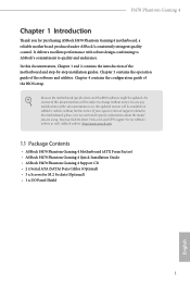
... to turn off (S5). The LED is in S4 sleep state or powered off your chassis front panel module to this header according to the motherboard. H470 Phantom Gaming 4 2.6 Onboard Headers and Connectors Onboard headers and connectors are matched correctly. You may differ by chassis. PLED (System Power LED): Connect to perform a normal restart...
... to turn off (S5). The LED is in S4 sleep state or powered off your chassis front panel module to this header according to the motherboard. H470 Phantom Gaming 4 2.6 Onboard Headers and Connectors Onboard headers and connectors are matched correctly. You may differ by chassis. PLED (System Power LED): Connect to perform a normal restart...

User Manual
Page 26
...) (see p.7, No. 20) SATA3_2 SATA3_0 SATA3_3 SATA3_1 SATA3_4 SATA3_5 These six SATA3 connectors support SATA data cables for internal storage devices with up to this motherboard. Please connect the chassis power LED and the chassis speaker to 6.0 Gb/s data transfer rate. * If M2_1 is occupied by a SATA-type M.2 device, SATA3_5 will...
...) (see p.7, No. 20) SATA3_2 SATA3_0 SATA3_3 SATA3_1 SATA3_4 SATA3_5 These six SATA3 connectors support SATA data cables for internal storage devices with up to this motherboard. Please connect the chassis power LED and the chassis speaker to 6.0 Gb/s data transfer rate. * If M2_1 is occupied by a SATA-type M.2 device, SATA3_5 will...
User Manual
Page 27
... 3.2 Gen1 header can support two ports. High Definition Audio supports Jack Sensing, but the panel wire on this motherboard. Connect Audio_R (RIN) to OUT2_R and Audio_L (LIN) to function correctly. Vbus IntA_PA_SSRXIntA_PA_SSRX+ GND IntA_PA_SSTXIntA_PA_SSTX+ GND ...+ GND IntA_PA_SSTXIntA_PA_SSTX+ GND IntA_PA_DIntA_PA_D+ Vbus IntA_PB_SSRXIntA_PB_SSRX+ GND IntA_PB_SSTXIntA_PB_SSTX+ GND IntA_PB_DIntA_PB_D+ Dummy 1 There are for the HD audio panel only. H470 Phantom Gaming 4 USB 3.2 Gen1 Headers (19-pin USB3_3_4) (see p.7, No. 11) (19-pin USB3_5_6) (see p.7, No. 29)...
... 3.2 Gen1 header can support two ports. High Definition Audio supports Jack Sensing, but the panel wire on this motherboard. Connect Audio_R (RIN) to OUT2_R and Audio_L (LIN) to function correctly. Vbus IntA_PA_SSRXIntA_PA_SSRX+ GND IntA_PA_SSTXIntA_PA_SSTX+ GND ...+ GND IntA_PA_SSTXIntA_PA_SSTX+ GND IntA_PA_DIntA_PA_D+ Vbus IntA_PB_SSRXIntA_PB_SSRX+ GND IntA_PB_SSTXIntA_PB_SSTX+ GND IntA_PB_DIntA_PB_D+ Dummy 1 There are for the HD audio panel only. H470 Phantom Gaming 4 USB 3.2 Gen1 Headers (19-pin USB3_3_4) (see p.7, No. 11) (19-pin USB3_5_6) (see p.7, No. 29)...

User Manual
Page 28
.../WP) (see p.7, No. 17) 1 GND 2 FAN_VOLTAGE 3 CHA_FAN_SPEED 4 FAN_SPEED_CONTROL FAN_SPEED_CONTROL 4 CHA_FAN_SPEED 3 FAN_VOLTAGE 2 GND 1 This motherboard provides four 4-Pin water cooling chassis fan connectors. Chassis/Water Pump Fan Connectors (4-pin CHA_FAN1/WP) (see p.7, No. 12) (4-pin...CHA_FAN3/WP) (see p.7, No. 23) (4-pin CHA_FAN4/WP) (see p.7, No. 6) FAN_VOLTAGE CPU_FAN_SPEED GND FAN_SPEED_CONTROL 1 2 3 4 This motherboard provides a 4-Pin water cooling CPU fan connector. English 22 If you plan to connect a 3-Pin CPU water cooler fan, please connect it ...
.../WP) (see p.7, No. 17) 1 GND 2 FAN_VOLTAGE 3 CHA_FAN_SPEED 4 FAN_SPEED_CONTROL FAN_SPEED_CONTROL 4 CHA_FAN_SPEED 3 FAN_VOLTAGE 2 GND 1 This motherboard provides four 4-Pin water cooling chassis fan connectors. Chassis/Water Pump Fan Connectors (4-pin CHA_FAN1/WP) (see p.7, No. 12) (4-pin...CHA_FAN3/WP) (see p.7, No. 23) (4-pin CHA_FAN4/WP) (see p.7, No. 6) FAN_VOLTAGE CPU_FAN_SPEED GND FAN_SPEED_CONTROL 1 2 3 4 This motherboard provides a 4-Pin water cooling CPU fan connector. English 22 If you plan to connect a 3-Pin CPU water cooler fan, please connect it ...
User Manual
Page 29
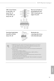
To use a 4-pin 4 1 ATX power supply, please plug it along Pin 1 and Pin 5. H470 Phantom Gaming 4 ATX 12V Power Connector (8-pin ATX12V1) (see p.7, No. 1) ATX 12V Power Connector (4-pin ATX12V2) (see p.7, No. 31) SPI_DQ3 +3.3V TPM_Present CLK SPI_MOSI RST# TPM_PIRQ 1 SPI_TPM_CS# ... connect a Thunderbolt™ add-in only one orientation. SPI TPM Header (13-pin SPI_TPM_J1) (see p.7, No. 18) Thunderbolt AIC Connector (5-pin TB1) (see p.7, No. 2) This motherboard provides 8 5 an 8-pin ATX 12V power connector.
To use a 4-pin 4 1 ATX power supply, please plug it along Pin 1 and Pin 5. H470 Phantom Gaming 4 ATX 12V Power Connector (8-pin ATX12V1) (see p.7, No. 1) ATX 12V Power Connector (4-pin ATX12V2) (see p.7, No. 31) SPI_DQ3 +3.3V TPM_Present CLK SPI_MOSI RST# TPM_PIRQ 1 SPI_TPM_CS# ... connect a Thunderbolt™ add-in only one orientation. SPI TPM Header (13-pin SPI_TPM_J1) (see p.7, No. 18) Thunderbolt AIC Connector (5-pin TB1) (see p.7, No. 2) This motherboard provides 8 5 an 8-pin ATX 12V power connector.

User Manual
Page 32
... minimum power your graphics card vendor for details.) English 26 2.8 CrossFireXTM and Quad CrossFireXTM Operation Guide This motherboard supports CrossFireXTM and Quad CrossFireXTM that allows you pair a 12-pipe CrossFireXTM Edition card with this motherboard. Download the drivers from the AMD's website: www.amd.com 3. You should only use a AMD certified PSU...
... minimum power your graphics card vendor for details.) English 26 2.8 CrossFireXTM and Quad CrossFireXTM Operation Guide This motherboard supports CrossFireXTM and Quad CrossFireXTM that allows you pair a 12-pipe CrossFireXTM Edition card with this motherboard. Download the drivers from the AMD's website: www.amd.com 3. You should only use a AMD certified PSU...


