
Intel Rapid Storage Guide
Page 12
Enable RAID in System BIOS Use the instructions included with your motherboard to enter the option ROM user interface. 2. Click the Storage Configuration menu. 4. When the Intel Rapid Storage Technology option ROM status screen appears during operating system setup. Use the up or down arrow keys to select the strip size and press Enter. 5. Press Enter to RAID. 5. Switch the SATA Operation Mode option to select the physical disks. 6. Unless you have selected RAID 1, use the up or down arrow keys to scroll through...
Enable RAID in System BIOS Use the instructions included with your motherboard to enter the option ROM user interface. 2. Click the Storage Configuration menu. 4. When the Intel Rapid Storage Technology option ROM status screen appears during operating system setup. Use the up or down arrow keys to select the strip size and press Enter. 5. Press Enter to RAID. 5. Switch the SATA Operation Mode option to select the physical disks. 6. Unless you have selected RAID 1, use the up or down arrow keys to scroll through...
Intel Rapid Storage Guide
Page 13
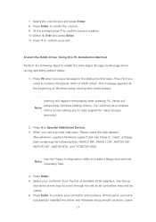
... your controller and continue. Press Y to install a third party SCSI or RAID driver. Nothing will temporarily continue loading drivers. Use the Floppy Configuration Utility to create a floppy disk with a screen asking you see a message in the status line that says, Please insert the disk labeled Manufacturer-supplied hardware support disk into Drive A:, insert ;a floppy disk containing the following steps to confirm your exit. Press Enter to install the Intel Rapid Storage Technology driver during text-mode...
... your controller and continue. Press Y to install a third party SCSI or RAID driver. Nothing will temporarily continue loading drivers. Use the Floppy Configuration Utility to create a floppy disk with a screen asking you see a message in the status line that says, Please insert the disk labeled Manufacturer-supplied hardware support disk into Drive A:, insert ;a floppy disk containing the following steps to confirm your exit. Press Enter to install the Intel Rapid Storage Technology driver during text-mode...

Intel Rapid Storage Guide
Page 16
... a floppy drive on Microsoft Windows 7 and Microsoft Windows 8 because Intel provided a RAID driver as part of the final package. Press F6 when you see a prompt that says, Please insert the disk labeled Manufacturer-supplied hardware support disk into Drive A:, insert a floppy disk containing the following steps to install the Intel® Rapid Storage Technology driver using F6 when in AHCI/RAID mode In order to install an operating system onto a single Serial ATA hard drive when...
... a floppy drive on Microsoft Windows 7 and Microsoft Windows 8 because Intel provided a RAID driver as part of the final package. Press F6 when you see a prompt that says, Please insert the disk labeled Manufacturer-supplied hardware support disk into Drive A:, insert a floppy disk containing the following steps to install the Intel® Rapid Storage Technology driver using F6 when in AHCI/RAID mode In order to install an operating system onto a single Serial ATA hard drive when...

RAID Installation Guide
Page 7
... 4: Install Windows® 10 64-bit OS on how to set SATA Mode Selection to save the configuration changes and exit setup. STEP 2: Use ASRock Easy RAID Installer Easy RAID Installer can copy the RAID driver from a support CD to your USB storage device with RAID functions, please follow the procedures below. Press [Enter] to complete the process. Plug in your system, and press key to enter BIOS setup utility. 2.3 Installing Windows® 10 64-bit With RAID Functions If you want to install Windows...
... 4: Install Windows® 10 64-bit OS on how to set SATA Mode Selection to save the configuration changes and exit setup. STEP 2: Use ASRock Easy RAID Installer Easy RAID Installer can copy the RAID driver from a support CD to your USB storage device with RAID functions, please follow the procedures below. Press [Enter] to complete the process. Plug in your system, and press key to enter BIOS setup utility. 2.3 Installing Windows® 10 64-bit With RAID Functions If you want to install Windows...

User Manual
Page 4
... Contents 1 1.2 Specifications 2 1.3 Motherboard Layout 7 1.4 I/O Panel 9 Chapter 2 Installation 11 2.1 Installing the CPU 12 2.2 Installing the CPU Fan and Heatsink 15 2.3 Installing Memory Modules (DIMM) 16 2.4 Expansion Slots (PCI Express Slots) 18 2.5 Jumpers Setup 19 2.6 Onboard Headers and Connectors 20 2.7 CrossFireXTM and Quad CrossFireXTM Operation Guide 25 2.7.1 Installing Two CrossFireXTM-Ready Graphics Cards 25 2.7.2 Driver Installation and Setup 27 2.8 M.2 WiFi/BT Module and Intel® CNVi (Integrated WiFi/BT) Installation Guide 28 2.9 M.2_SSD...
... Contents 1 1.2 Specifications 2 1.3 Motherboard Layout 7 1.4 I/O Panel 9 Chapter 2 Installation 11 2.1 Installing the CPU 12 2.2 Installing the CPU Fan and Heatsink 15 2.3 Installing Memory Modules (DIMM) 16 2.4 Expansion Slots (PCI Express Slots) 18 2.5 Jumpers Setup 19 2.6 Onboard Headers and Connectors 20 2.7 CrossFireXTM and Quad CrossFireXTM Operation Guide 25 2.7.1 Installing Two CrossFireXTM-Ready Graphics Cards 25 2.7.2 Driver Installation and Setup 27 2.8 M.2 WiFi/BT Module and Intel® CNVi (Integrated WiFi/BT) Installation Guide 28 2.9 M.2_SSD...
User Manual
Page 7
...; 2 x Serial ATA (SATA) Data Cables (Optional) • 1 x I/O Panel Shield • 3 x Screws for specific information about the model you for purchasing ASRock H370 Pro4 motherboard, a reliable motherboard produced under ASRock's consistently stringent quality control. It delivers excellent performance with robust design conforming to ASRock's commitment to change without further notice. H370 Pro4 Chapter 1 Introduction Thank you are using. Chapter 4 contains the configuration guide of the software and utilities. Chapter 3 contains the operation guide of the BIOS setup...
...; 2 x Serial ATA (SATA) Data Cables (Optional) • 1 x I/O Panel Shield • 3 x Screws for specific information about the model you for purchasing ASRock H370 Pro4 motherboard, a reliable motherboard produced under ASRock's consistently stringent quality control. It delivers excellent performance with robust design conforming to ASRock's commitment to change without further notice. H370 Pro4 Chapter 1 Introduction Thank you are using. Chapter 4 contains the configuration guide of the software and utilities. Chapter 3 contains the operation guide of the BIOS setup...
User Manual
Page 11
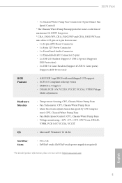
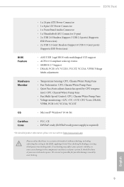
...; 2 x USB 3.1 Gen1 Headers (Support 4 USB 3.1 Gen1 ports) (Supports ESD Protection) BIOS Feature • AMI UEFI Legal BIOS with multilingual GUI support • ACPI 6.0 Compliant wake up events • SMBIOS 2.7 Support • DRAM, PCH 1.0V, VCCIO, VCCST, VCCSA, VPPM Voltage Multi-adjustment Hardware Monitor • Temperature Sensing: CPU, Chassis/Water Pump Fans • Fan Tachometer: CPU, Chassis/Water Pump Fans • Quiet Fan (Auto adjust chassis fan speed by CPU tempera- H370 Pro4 • 3 x Chassis/Water Pump Fan Connectors (4-pin) (Smart Fan Speed Control) * The Chassis...
...; 2 x USB 3.1 Gen1 Headers (Support 4 USB 3.1 Gen1 ports) (Supports ESD Protection) BIOS Feature • AMI UEFI Legal BIOS with multilingual GUI support • ACPI 6.0 Compliant wake up events • SMBIOS 2.7 Support • DRAM, PCH 1.0V, VCCIO, VCCST, VCCSA, VPPM Voltage Multi-adjustment Hardware Monitor • Temperature Sensing: CPU, Chassis/Water Pump Fans • Fan Tachometer: CPU, Chassis/Water Pump Fans • Quiet Fan (Auto adjust chassis fan speed by CPU tempera- H370 Pro4 • 3 x Chassis/Water Pump Fan Connectors (4-pin) (Smart Fan Speed Control) * The Chassis...

User Manual
Page 14
...) 7 USB 3.1 Gen1 Header (USB3_3_4) 8 SATA3 Connector (SATA3_3) 9 SATA3 Connector (SATA3_2) 10 SATA3 Connector (SATA3_1) 11 SATA3 Connector (SATA3_0) 12 Power LED and Speaker Header (SPK_PLED1) 13 SATA3 Connector (SATA3_4) 14 SATA3 Connector (SATA3_5) 15 System Panel Header (PANEL1) 16 Chassis Fan / Waterpump Fan Connector (CHA_FAN3/WP) 17 Chassis Fan / Waterpump Fan Connector (CHA_FAN1/WP) 18 USB 3.1 Gen1 Header (USB3_5_6) 19 USB 2.0 Header (USB_3_4) 20 USB 2.0 Header (USB_5) 21 TPM Header (TPMS1) 22 COM Port Header (COM1) 23 Front Panel Audio Header (HD_AUDIO1) 24 Clear CMOS Jumper (CLRMOS1...
...) 7 USB 3.1 Gen1 Header (USB3_3_4) 8 SATA3 Connector (SATA3_3) 9 SATA3 Connector (SATA3_2) 10 SATA3 Connector (SATA3_1) 11 SATA3 Connector (SATA3_0) 12 Power LED and Speaker Header (SPK_PLED1) 13 SATA3 Connector (SATA3_4) 14 SATA3 Connector (SATA3_5) 15 System Panel Header (PANEL1) 16 Chassis Fan / Waterpump Fan Connector (CHA_FAN3/WP) 17 Chassis Fan / Waterpump Fan Connector (CHA_FAN1/WP) 18 USB 3.1 Gen1 Header (USB3_5_6) 19 USB 2.0 Header (USB_3_4) 20 USB 2.0 Header (USB_5) 21 TPM Header (TPMS1) 22 COM Port Header (COM1) 23 Front Panel Audio Header (HD_AUDIO1) 24 Clear CMOS Jumper (CLRMOS1...

User Manual
Page 31
... slot and the other graphics card to three identical PCI Express x16 graphics cards. 1. Different CrossFireXTM cards may require different methods to use a AMD certified PSU. You should only use identical CrossFireXTM-ready graphics cards that are properly seated on the top of the graphics cards. (The CrossFire Bridge is recommended to enable CrossFireXTM. Download the drivers from the AMD's website: www.amd.com 3. H370 Pro4 2.7 CrossFireXTM and Quad CrossFireXTM Operation Guide This motherboard supports...
... slot and the other graphics card to three identical PCI Express x16 graphics cards. 1. Different CrossFireXTM cards may require different methods to use a AMD certified PSU. You should only use identical CrossFireXTM-ready graphics cards that are properly seated on the top of the graphics cards. (The CrossFire Bridge is recommended to enable CrossFireXTM. Download the drivers from the AMD's website: www.amd.com 3. H370 Pro4 2.7 CrossFireXTM and Quad CrossFireXTM Operation Guide This motherboard supports...
User Manual
Page 33
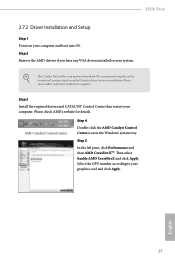
... an optional download. We recommend using this utility to uninstall any VGA drivers installed in the Windows® system tray. AMD Catalyst Control Center Step 4 Double-click the AMD Catalyst Control Center icon in your graphics card and click Apply. English 27 Then select Enable AMD CrossFireX and click Apply. Select the GPU number according to installation. H370 Pro4 2.7.2 Driver Installation and Setup Step 1 Power on your computer. Please check AMD's website for AMD driver updates. Step 3 Install...
... an optional download. We recommend using this utility to uninstall any VGA drivers installed in the Windows® system tray. AMD Catalyst Control Center Step 4 Double-click the AMD Catalyst Control Center icon in your graphics card and click Apply. English 27 Then select Enable AMD CrossFireX and click Apply. Select the GPU number according to installation. H370 Pro4 2.7.2 Driver Installation and Setup Step 1 Power on your computer. Please check AMD's website for AMD driver updates. Step 3 Install...
User Manual
Page 46
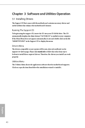
... display the menu. Chapter 3 Software and Utilities Operation 3.1 Installing Drivers The Support CD that comes with the motherboard contains necessary drivers and useful utilities that the motherboard supports. The CD automatically displays the Main Menu if "AUTORUN" is enabled in the Support CD to your system will be auto-detected and listed on the file "ASRSETUP.EXE" in your CD-ROM drive. Therefore, the drivers you install can work properly. If the Main Menu does not appear automatically, locate...
... display the menu. Chapter 3 Software and Utilities Operation 3.1 Installing Drivers The Support CD that comes with the motherboard contains necessary drivers and useful utilities that the motherboard supports. The CD automatically displays the Main Menu if "AUTORUN" is enabled in the Support CD to your system will be auto-detected and listed on the file "ASRSETUP.EXE" in your CD-ROM drive. Therefore, the drivers you install can work properly. If the Main Menu does not appear automatically, locate...
User Manual
Page 69
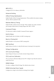
... DRAM memory training for the DRAM Activating Power Supply. 63 English DRAM Activating Power Supply Configure the voltage for booting faster. Exit On Failure Enable/Disable Exit On Failure for Memory MRS MR6. DRAM Voltage Use this item to reset system if MRC training fails. Advanced Setting ASRock Timing Optimization Enable/Disable ASRock Timing Optimization. When enabled, the system will use ASRock optimized value. Realtime Memory Timing Enable/Disable realtime memory timings. H370 Pro4 MRS tCCD_L Configure the tCL for MRC training steps. Voltage Configuration CPU Core...
... DRAM memory training for the DRAM Activating Power Supply. 63 English DRAM Activating Power Supply Configure the voltage for booting faster. Exit On Failure Enable/Disable Exit On Failure for Memory MRS MR6. DRAM Voltage Use this item to reset system if MRC training fails. Advanced Setting ASRock Timing Optimization Enable/Disable ASRock Timing Optimization. When enabled, the system will use ASRock optimized value. Realtime Memory Timing Enable/Disable realtime memory timings. H370 Pro4 MRS tCCD_L Configure the tCL for MRC training steps. Voltage Configuration CPU Core...

User Manual
Page 74
... speed for Directed I/O helps your virtual machine monitor better utilize hardware by improving application compatibility and reliability, and providing additional levels of manageability, security, isolation, and I/O performance. VT-d Intel® Virtualization Technology for PCIE1. 4.6.2 Chipset Configuration Primary Graphics Adapter Select a primary VGA. Above 4G Decoding Enable or disable 64bit capable Devices to be decoded in Above 4G Address Space (only if the system supports 64 bit PCI...
... speed for Directed I/O helps your virtual machine monitor better utilize hardware by improving application compatibility and reliability, and providing additional levels of manageability, security, isolation, and I/O performance. VT-d Intel® Virtualization Technology for PCIE1. 4.6.2 Chipset Configuration Primary Graphics Adapter Select a primary VGA. Above 4G Decoding Enable or disable 64bit capable Devices to be decoded in Above 4G Address Space (only if the system supports 64 bit PCI...

User Manual
Page 75
... integrated graphics processor when the system boots up. PCIE5 Link Speed Select the link speed for enhanced PCI Express power saving in OS. PCH PCIE ASPM Support This option enables/disables the ASPM support for all PCH PCIE devices. Front Panel Enable/disable front panel HD audio. 69 English DMI ASPM Support This option enables/disables the control of ASPM on CPU side of memory that is allocated to enable onboard HD audio and automatically disable it when a sound card is installed. Share Memory Configure the size of...
... integrated graphics processor when the system boots up. PCIE5 Link Speed Select the link speed for enhanced PCI Express power saving in OS. PCH PCIE ASPM Support This option enables/disables the ASPM support for all PCH PCIE devices. Front Panel Enable/disable front panel HD audio. 69 English DMI ASPM Support This option enables/disables the control of ASPM on CPU side of memory that is allocated to enable onboard HD audio and automatically disable it when a sound card is installed. Share Memory Configure the size of...

User Manual
Page 78
... Ridge Workaround for the Thunderbolt ports. ACPI Notify on TBT hot-plug When enabled, BIOS generates software SMI to assign resource to allow booting from Bootable devices which are present behind Thunderbolt. 4.6.4 Intel® Thunderbolt Discrete Thunderbolt(TM) Support Enable or disable the Discrete Thunderbolt(TM) Support. Thunderbolt Boot Support Enabled to TBT devices. SW SMI on TBT Hot-plug When enabled, BIOS generates ACPI Notify. 72 English Security Level...
... Ridge Workaround for the Thunderbolt ports. ACPI Notify on TBT hot-plug When enabled, BIOS generates software SMI to assign resource to allow booting from Bootable devices which are present behind Thunderbolt. 4.6.4 Intel® Thunderbolt Discrete Thunderbolt(TM) Support Enable or disable the Discrete Thunderbolt(TM) Support. Thunderbolt Boot Support Enabled to TBT devices. SW SMI on TBT Hot-plug When enabled, BIOS generates ACPI Notify. 72 English Security Level...
User Manual
Page 84
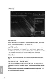
... the drivers please change the SATA mode to plug in your UEFI. DHCP (Auto IP), Auto ASRock Internet Flash downloads and updates the latest UEFI firmware version from the support CD to update your USB pen drive before using this function. 78 English Please setup network configuration before using Internet Flash. *For BIOS backup and recovery purpose, it is recommended to RAID, then you to copy the RAID driver from our servers for you are having trouble with your USB storage device. Easy RAID Installer Easy RAID Installer...
... the drivers please change the SATA mode to plug in your UEFI. DHCP (Auto IP), Auto ASRock Internet Flash downloads and updates the latest UEFI firmware version from the support CD to update your USB pen drive before using this function. 78 English Please setup network configuration before using Internet Flash. *For BIOS backup and recovery purpose, it is recommended to RAID, then you to copy the RAID driver from our servers for you are having trouble with your USB storage device. Easy RAID Installer Easy RAID Installer...

User Manual
Page 85
H370 Pro4 Internet Setting Enable or disable sound effects in the setup utility. UEFI Download Server Select a server to configure internet connection settings for Internet Flash. English 79 Network Configuration Use this to download the UEFI firmware.
H370 Pro4 Internet Setting Enable or disable sound effects in the setup utility. UEFI Download Server Select a server to configure internet connection settings for Internet Flash. English 79 Network Configuration Use this to download the UEFI firmware.

User Manual
Page 89
... UEFI Setup Utility. Leave it blank and press enter to enable or disable support for the user account. Only the administrator has authority to remove the password. Supervisor Password Set or change the password for the system. Users are unable to use discrete TPM Module. 83 English Disable this option to change the settings in ME. Leave it blank and press enter to change the settings in the UEFI Setup Utility. Secure Boot Use this item to remove the password. H370 Pro4...
... UEFI Setup Utility. Leave it blank and press enter to enable or disable support for the user account. Only the administrator has authority to remove the password. Supervisor Password Set or change the password for the system. Users are unable to use discrete TPM Module. 83 English Disable this option to change the settings in ME. Leave it blank and press enter to change the settings in the UEFI Setup Utility. Secure Boot Use this item to remove the password. H370 Pro4...

Quick Installation Guide
Page 4
...) 7 USB 3.1 Gen1 Header (USB3_3_4) 8 SATA3 Connector (SATA3_3) 9 SATA3 Connector (SATA3_2) 10 SATA3 Connector (SATA3_1) 11 SATA3 Connector (SATA3_0) 12 Power LED and Speaker Header (SPK_PLED1) 13 SATA3 Connector (SATA3_4) 14 SATA3 Connector (SATA3_5) 15 System Panel Header (PANEL1) 16 Chassis Fan / Waterpump Fan Connector (CHA_FAN3/WP) 17 Chassis Fan / Waterpump Fan Connector (CHA_FAN1/WP) 18 USB 3.1 Gen1 Header (USB3_5_6) 19 USB 2.0 Header (USB_3_4) 20 USB 2.0 Header (USB_5) 21 TPM Header (TPMS1) 22 COM Port Header (COM1) 23 Front Panel Audio Header (HD_AUDIO1) 24 Clear CMOS Jumper (CLRMOS1...
...) 7 USB 3.1 Gen1 Header (USB3_3_4) 8 SATA3 Connector (SATA3_3) 9 SATA3 Connector (SATA3_2) 10 SATA3 Connector (SATA3_1) 11 SATA3 Connector (SATA3_0) 12 Power LED and Speaker Header (SPK_PLED1) 13 SATA3 Connector (SATA3_4) 14 SATA3 Connector (SATA3_5) 15 System Panel Header (PANEL1) 16 Chassis Fan / Waterpump Fan Connector (CHA_FAN3/WP) 17 Chassis Fan / Waterpump Fan Connector (CHA_FAN1/WP) 18 USB 3.1 Gen1 Header (USB3_5_6) 19 USB 2.0 Header (USB_3_4) 20 USB 2.0 Header (USB_5) 21 TPM Header (TPMS1) 22 COM Port Header (COM1) 23 Front Panel Audio Header (HD_AUDIO1) 24 Clear CMOS Jumper (CLRMOS1...
Quick Installation Guide
Page 11
... Voltage Multi-adjustment Hardware Monitor • Temperature Sensing: CPU, Chassis/Water Pump Fans • Fan Tachometer: CPU, Chassis/Water Pump Fans • Quiet Fan (Auto adjust chassis fan speed by overclocking. H370 Pro4 • 1 x 24 pin ATX Power Connector • 1 x 8 pin 12V Power Connector • 1 x Front Panel Audio Connector • 1 x Thunderbolt AIC Connector (5-pin) • 2 x USB 2.0 Headers (Support 3 USB 2.0 ports) (Supports ESD Protection) • 2 x USB 3.1 Gen1 Headers (Support 4 USB 3.1 Gen1 ports) (Supports ESD Protection) BIOS Feature • AMI UEFI...
... Voltage Multi-adjustment Hardware Monitor • Temperature Sensing: CPU, Chassis/Water Pump Fans • Fan Tachometer: CPU, Chassis/Water Pump Fans • Quiet Fan (Auto adjust chassis fan speed by overclocking. H370 Pro4 • 1 x 24 pin ATX Power Connector • 1 x 8 pin 12V Power Connector • 1 x Front Panel Audio Connector • 1 x Thunderbolt AIC Connector (5-pin) • 2 x USB 2.0 Headers (Support 3 USB 2.0 ports) (Supports ESD Protection) • 2 x USB 3.1 Gen1 Headers (Support 4 USB 3.1 Gen1 ports) (Supports ESD Protection) BIOS Feature • AMI UEFI...


