
User Manual
Page 4
... 1 1.2 Specifications 2 1.3 Motherboard Layout 6 1.4 I/O Panel 8 Chapter 2 Installation 10 2.1 Installing the CPU 11 2.2 Installing the CPU Fan and Heatsink 14 2.3 Installing Memory Modules (DIMM) 15 2.4 Expansion Slots (PCI and PCI Express Slots) 17 2.5 Jumpers Setup 18 2.6 Onboard Headers and Connectors 19 2.7 M.2_SSD (NGFF) Module Installation Guide 23 Chapter 3 Software and Utilities Operation 27 3.1 Installing Drivers 27 3.2 A-Tuning 28 3.3 ASRock Live Update & APP Shop 31 3.3.1 UI Overview 31 3.3.2 Apps 32 3.3.3 BIOS & Drivers 35 3.3.4 Setting 36
... 1 1.2 Specifications 2 1.3 Motherboard Layout 6 1.4 I/O Panel 8 Chapter 2 Installation 10 2.1 Installing the CPU 11 2.2 Installing the CPU Fan and Heatsink 14 2.3 Installing Memory Modules (DIMM) 15 2.4 Expansion Slots (PCI and PCI Express Slots) 17 2.5 Jumpers Setup 18 2.6 Onboard Headers and Connectors 19 2.7 M.2_SSD (NGFF) Module Installation Guide 23 Chapter 3 Software and Utilities Operation 27 3.1 Installing Drivers 27 3.2 A-Tuning 28 3.3 ASRock Live Update & APP Shop 31 3.3.1 UI Overview 31 3.3.2 Apps 32 3.3.3 BIOS & Drivers 35 3.3.4 Setting 36
User Manual
Page 7
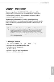
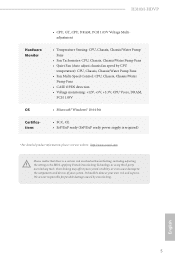
...-HDVP Quick Installation Guide • ASRock H310M-HDVP Support CD • 1 x I/O Panel Shield • 2 x Serial ATA (SATA) Data Cables (Optional) • 1 x Screw for purchasing ASRock H310M-HDVP motherboard, a reliable motherboard produced under ASRock's consistently stringent quality control. You may find the latest VGA cards and CPU support list on ASRock's website without notice. Chapter 4 contains the configuration guide of the software and utilities. If you for M.2 Socket (Optional) 1 English Because the motherboard specifications and the BIOS software might be updated...
...-HDVP Quick Installation Guide • ASRock H310M-HDVP Support CD • 1 x I/O Panel Shield • 2 x Serial ATA (SATA) Data Cables (Optional) • 1 x Screw for purchasing ASRock H310M-HDVP motherboard, a reliable motherboard produced under ASRock's consistently stringent quality control. You may find the latest VGA cards and CPU support list on ASRock's website without notice. Chapter 4 contains the configuration guide of the software and utilities. If you for M.2 Socket (Optional) 1 English Because the motherboard specifications and the BIOS software might be updated...
User Manual
Page 9
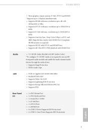
... to 2 displays simultaneously • Supports HDMI with max. H310M-HDVP • Three graphics output options: D-Sub, DVI-D and HDMI * Supports up to 1920x1200 @ 60Hz • Supports D-Sub with max. resolution up to use an HD front panel audio module and enable the multi-channel audio feature through the audio driver. • Supports Surge Protection • ELNA Audio Caps LAN • PCIE x1 Gigabit LAN 10/100/1000 Mb/s • Realtek RTL8111GN • Supports Wake-On-LAN • Supports Lightning...
... to 2 displays simultaneously • Supports HDMI with max. H310M-HDVP • Three graphics output options: D-Sub, DVI-D and HDMI * Supports up to 1920x1200 @ 60Hz • Supports D-Sub with max. resolution up to use an HD front panel audio module and enable the multi-channel audio feature through the audio driver. • Supports Surge Protection • ELNA Audio Caps LAN • PCIE x1 Gigabit LAN 10/100/1000 Mb/s • Realtek RTL8111GN • Supports Wake-On-LAN • Supports Lightning...
User Manual
Page 10
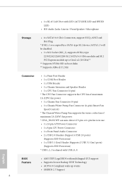
...be disabled. • 1 x M.2 Socket (M2_1), supports M Key type 2230/2242/2260/2280 M.2 SATA3 6.0 Gb/s module and M.2 PCI Express module up to Gen2 x2 (10 Gb/s)** ** Supports NVMe SSD as boot disks ** Supports ASRock U.2 Kit Connector • 1 x Print Port Header • 1 x COM Port Header • 1 x TPM Header • 1 x Chassis Intrusion and Speaker Header • 1 x CPU Fan Connector (4-pin) * The CPU Fan Connector supports the CPU fan of maximum 1A (12W) fan power. • 1 x Chassis Fan Connector (4-pin) • 1 x Chassis/Water Pump Fan Connector (4-pin) (Smart Fan Speed Control...
...be disabled. • 1 x M.2 Socket (M2_1), supports M Key type 2230/2242/2260/2280 M.2 SATA3 6.0 Gb/s module and M.2 PCI Express module up to Gen2 x2 (10 Gb/s)** ** Supports NVMe SSD as boot disks ** Supports ASRock U.2 Kit Connector • 1 x Print Port Header • 1 x COM Port Header • 1 x TPM Header • 1 x Chassis Intrusion and Speaker Header • 1 x CPU Fan Connector (4-pin) * The CPU Fan Connector supports the CPU fan of maximum 1A (12W) fan power. • 1 x Chassis Fan Connector (4-pin) • 1 x Chassis/Water Pump Fan Connector (4-pin) (Smart Fan Speed Control...
User Manual
Page 11
... Fan (Auto adjust chassis fan speed by overclocking. It should be done at your system. We are not responsible for possible damage caused by CPU temperature): CPU, Chassis, Chassis/Water Pump Fans • Fan Multi-Speed Control: CPU, Chassis, Chassis/Water Pump Fans • CASE OPEN detection • Voltage monitoring: +12V, +5V, +3.3V, CPU Vcore, DRAM, PCH 1.05V • Microsoft® Windows® 10 64-bit • FCC, CE • ErP/EuP ready (ErP/EuP ready power supply...
... Fan (Auto adjust chassis fan speed by overclocking. It should be done at your system. We are not responsible for possible damage caused by CPU temperature): CPU, Chassis, Chassis/Water Pump Fans • Fan Multi-Speed Control: CPU, Chassis, Chassis/Water Pump Fans • CASE OPEN detection • Voltage monitoring: +12V, +5V, +3.3V, CPU Vcore, DRAM, PCH 1.05V • Microsoft® Windows® 10 64-bit • FCC, CE • ErP/EuP ready (ErP/EuP ready power supply...
User Manual
Page 13
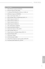
... Power Connector (ATX12V1) 2 CPU Fan Connector (CPU_FAN1) 3 2 x 288-pin DDR4 DIMM Slots (DDR4_A1, DDR4_B1) 4 ATX Power Connector (ATXPWR1) 5 USB 3.1 Gen1 Header (USB3_2_3) 6 USB 2.0 Header (USB_8_9) (shared with USB3_2_3) 7 SATA3 Connector (SATA3_3) 8 SATA3 Connector (SATA3_2) 9 SATA3 Connector (SATA3_1) 10 SATA3 Connector (SATA3_0) 11 Clear CMOS Jumper (CLRMOS1) 12 System Panel Header (PANEL1) 13 Chassis Fan Connector (CHA_FAN2) 14 USB 2.0 Header (USB_4_5) 15 Chassis Intrusion and Speaker Header (SPK_CI1) 16 Print Port Header (LPT1) 17 TPM Header (TPMS1) 18 COM Port Header (COM2) 19 Chassis...
... Power Connector (ATX12V1) 2 CPU Fan Connector (CPU_FAN1) 3 2 x 288-pin DDR4 DIMM Slots (DDR4_A1, DDR4_B1) 4 ATX Power Connector (ATXPWR1) 5 USB 3.1 Gen1 Header (USB3_2_3) 6 USB 2.0 Header (USB_8_9) (shared with USB3_2_3) 7 SATA3 Connector (SATA3_3) 8 SATA3 Connector (SATA3_2) 9 SATA3 Connector (SATA3_1) 10 SATA3 Connector (SATA3_0) 11 Clear CMOS Jumper (CLRMOS1) 12 System Panel Header (PANEL1) 13 Chassis Fan Connector (CHA_FAN2) 14 USB 2.0 Header (USB_4_5) 15 Chassis Intrusion and Speaker Header (SPK_CI1) 16 Print Port Header (LPT1) 17 TPM Header (TPMS1) 18 COM Port Header (COM2) 19 Chassis...
User Manual
Page 21
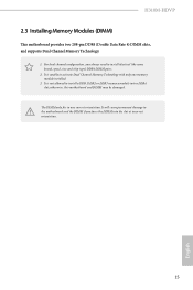
.... It is not allowed to install identical (the same brand, speed, size and chip-type) DDR4 DIMM pairs. 2. The DIMM only fits in one memory module installed. 3. It will cause permanent damage to activate Dual Channel Memory Technology with only one correct orientation. For dual channel configuration, you force the DIMM into a DDR4 slot; It is unable to the motherboard and the DIMM if you always...
.... It is not allowed to install identical (the same brand, speed, size and chip-type) DDR4 DIMM pairs. 2. The DIMM only fits in one memory module installed. 3. It will cause permanent damage to activate Dual Channel Memory Technology with only one correct orientation. For dual channel configuration, you force the DIMM into a DDR4 slot; It is unable to the motherboard and the DIMM if you always...
User Manual
Page 23
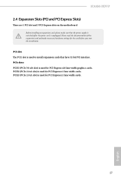
.... Please read the documentation of the expansion card and make sure that have 32-bit PCI interface. H310M-HDVP 2.4 Expansion Slots (PCI and PCI Express Slots) There are 1 PCI slot and 3 PCI Express slots on the motherboard. Before installing an expansion card, please make necessary hardware settings for PCI Express x16 lane width graphics cards. PCIE3 (PCIe 2.0 x1 slot) is used to install expansion cards that the power supply is switched off or the power cord is used for the card before you start the installation.
.... Please read the documentation of the expansion card and make sure that have 32-bit PCI interface. H310M-HDVP 2.4 Expansion Slots (PCI and PCI Express Slots) There are 1 PCI slot and 3 PCI Express slots on the motherboard. Before installing an expansion card, please make necessary hardware settings for PCI Express x16 lane width graphics cards. PCIE3 (PCIe 2.0 x1 slot) is used to install expansion cards that the power supply is switched off or the power cord is used for the card before you start the installation.
User Manual
Page 24
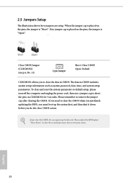
... BIOS option "Clear Status" to clear the CMOS when you just finish updating the BIOS, you must boot up the system first, and then shut it down before you clear the CMOS, the case open may be detected. 2.5 Jumpers Setup The illustration shows how jumpers are setup. To clear and reset the system parameters to default setup, please turn off the computer and unplug the power cord, then use a jumper cap to short the pins...
... BIOS option "Clear Status" to clear the CMOS when you just finish updating the BIOS, you must boot up the system first, and then shut it down before you clear the CMOS, the case open may be detected. 2.5 Jumpers Setup The illustration shows how jumpers are setup. To clear and reset the system parameters to default setup, please turn off the computer and unplug the power cord, then use a jumper cap to short the pins...
User Manual
Page 25
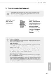
H310M-HDVP 2.6 Onboard Headers and Connectors Onboard headers and connectors are matched correctly. Placing jumper caps over these headers and connectors. HDLED (Hard Drive Activity LED): Connect to the hard drive activity LED on the chassis front panel. The LED keeps blinking when the system is in S1/S3 sleep state. The front panel design may configure the way to the motherboard. English 19 Do NOT place jumper caps over the headers and connectors will cause permanent damage to...
H310M-HDVP 2.6 Onboard Headers and Connectors Onboard headers and connectors are matched correctly. Placing jumper caps over these headers and connectors. HDLED (Hard Drive Activity LED): Connect to the hard drive activity LED on the chassis front panel. The LED keeps blinking when the system is in S1/S3 sleep state. The front panel design may configure the way to the motherboard. English 19 Do NOT place jumper caps over the headers and connectors will cause permanent damage to...
User Manual
Page 26
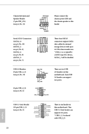
... P+ P- Chassis Intrusion and Speaker Header (7-pin SPK_CI1) (see p.6, No. 15) Serial ATA3 Connectors (SATA3_0: see p.6, No. 10) (SATA3_1: see p.6, No. 9) (SATA3_2: see p.6, No. 8) (SATA3_3: see p.6, No. 7) SATA3_1 SATA3_3 SATA3_0 SATA3_2 SPEAKER DUMMY DUMMY +5V 1 SIGNAL GND DUMMY Please connect the chassis power LED and the chassis speaker to 6.0 Gb/s data transfer rate. * If M2_1 is occupied by a SATA-type M.2 device, SATA3_3 will be disabled. Each USB 2.0 header can support two ports...
... P+ P- Chassis Intrusion and Speaker Header (7-pin SPK_CI1) (see p.6, No. 15) Serial ATA3 Connectors (SATA3_0: see p.6, No. 10) (SATA3_1: see p.6, No. 9) (SATA3_2: see p.6, No. 8) (SATA3_3: see p.6, No. 7) SATA3_1 SATA3_3 SATA3_0 SATA3_2 SPEAKER DUMMY DUMMY +5V 1 SIGNAL GND DUMMY Please connect the chassis power LED and the chassis speaker to 6.0 Gb/s data transfer rate. * If M2_1 is occupied by a SATA-type M.2 device, SATA3_3 will be disabled. Each USB 2.0 header can support two ports...
User Manual
Page 27
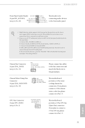
...This motherboard provides a 4-Pin CPU fan (Quiet Fan) connector. Chassis/Water Pump Fan 1 2 Connector 3 4 (4-pin CHA_FAN1/WP) (see p.6, No. 19) GND FAN_VOLTAGE CHA_FAN_SPEED FAN_SPEED_CONTROL This motherboard provides a 4-Pin water cooling chassis fan connectors. Connect Mic_IN (MIC) to function correctly. MIC_RET and OUT_RET are for connecting audio devices MIC2_R to Pin 1-3. 21 English High Definition Audio supports Jack Sensing, but the panel wire on the chassis must support HDA to MIC2_L. D. H310M-HDVP Front Panel Audio Header OUT_RET (9-pin HD_AUDIO1...
...This motherboard provides a 4-Pin CPU fan (Quiet Fan) connector. Chassis/Water Pump Fan 1 2 Connector 3 4 (4-pin CHA_FAN1/WP) (see p.6, No. 19) GND FAN_VOLTAGE CHA_FAN_SPEED FAN_SPEED_CONTROL This motherboard provides a 4-Pin water cooling chassis fan connectors. Connect Mic_IN (MIC) to function correctly. MIC_RET and OUT_RET are for connecting audio devices MIC2_R to Pin 1-3. 21 English High Definition Audio supports Jack Sensing, but the panel wire on the chassis must support HDA to MIC2_L. D. H310M-HDVP Front Panel Audio Header OUT_RET (9-pin HD_AUDIO1...
User Manual
Page 33
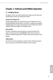
..., locate and double click on the support CD driver page. The CD automatically displays the Main Menu if "AUTORUN" is enabled in your system will be auto-detected and listed on the file "ASRSETUP.EXE" in the Support CD to your computer. Running The Support CD To begin using the support CD, insert the CD into your CD-ROM drive. Therefore, the drivers you install can work properly. H310M-HDVP Chapter 3 Software...
..., locate and double click on the support CD driver page. The CD automatically displays the Main Menu if "AUTORUN" is enabled in your system will be auto-detected and listed on the file "ASRSETUP.EXE" in the Support CD to your computer. Running The Support CD To begin using the support CD, insert the CD into your CD-ROM drive. Therefore, the drivers you install can work properly. H310M-HDVP Chapter 3 Software...
User Manual
Page 59
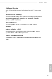
Intel Virtualization Technology Intel Virtualization Technology allows a platform to keep the CPU from overheating. Enable for better performance. H310M-HDVP CPU Thermal Throttling Enable CPU internal thermal control mechanisms to run multiple operating systems and applications in independent partitions, so that one computer system can function as multiple virtual systems. Hardware Prefetcher Automatically prefetch data and code for the processor. Adjacent Cache Line Prefetch Automatically prefetch the...
Intel Virtualization Technology Intel Virtualization Technology allows a platform to keep the CPU from overheating. Enable for better performance. H310M-HDVP CPU Thermal Throttling Enable CPU internal thermal control mechanisms to run multiple operating systems and applications in independent partitions, so that one computer system can function as multiple virtual systems. Hardware Prefetcher Automatically prefetch data and code for the processor. Adjacent Cache Line Prefetch Automatically prefetch the...
User Manual
Page 60
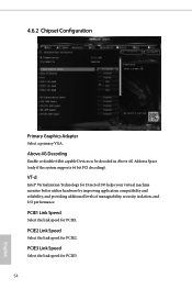
... supports 64 bit PCI decoding). PCIE1 Link Speed Select the link speed for PCIE2. PCIE2 Link Speed Select the link speed for PCIE1. PCIE3 Link Speed Select the link speed for Directed I/O helps your virtual machine monitor better utilize hardware by improving application compatibility and reliability, and providing additional levels of manageability, security, isolation, and I/O performance. VT-d Intel® Virtualization Technology for PCIE3. 54 English 4.6.2 Chipset Configuration...
... supports 64 bit PCI decoding). PCIE1 Link Speed Select the link speed for PCIE2. PCIE2 Link Speed Select the link speed for PCIE1. PCIE3 Link Speed Select the link speed for Directed I/O helps your virtual machine monitor better utilize hardware by improving application compatibility and reliability, and providing additional levels of manageability, security, isolation, and I/O performance. VT-d Intel® Virtualization Technology for PCIE3. 54 English 4.6.2 Chipset Configuration...
User Manual
Page 61
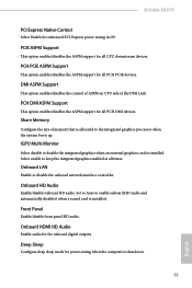
... enables/disables the control of ASPM on CPU side of memory that is installed. Share Memory Configure the size of the DMI Link. Onboard LAN Enable or disable the onboard network interface controller. PCH DMI ASPM Support This option enables/disables the ASPM support for the onboard digital outputs. Onboard HDMI HD Audio Enable audio for all PCH DMI devices. Front Panel Enable/disable front panel HD audio. H310M-HDVP PCI Express Native Control Select Enable for all CPU downstream devices. PCIE ASPM Support This option enables/disables the ASPM support for enhanced PCI Express power...
... enables/disables the control of ASPM on CPU side of memory that is installed. Share Memory Configure the size of the DMI Link. Onboard LAN Enable or disable the onboard network interface controller. PCH DMI ASPM Support This option enables/disables the ASPM support for the onboard digital outputs. Onboard HDMI HD Audio Enable audio for all PCH DMI devices. Front Panel Enable/disable front panel HD audio. H310M-HDVP PCI Express Native Control Select Enable for all CPU downstream devices. PCIE ASPM Support This option enables/disables the ASPM support for enhanced PCI Express power...
User Manual
Page 66
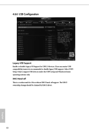
Select UEFI Setup Only to disable legacy USB support. 4.6.6 USB Configuration Legacy USB Support Enable or disable Legacy OS Support for OSes without XHCI hand-off support. XHCI Hand-off This is recommended to support USB devices under the UEFI setup and Windows/Linux operating systems only. The XHCI ownership change should be claimed by XHCI driver. 60 English If you encounter USB compatibility issues it is a workaround for USB 2.0 devices.
Select UEFI Setup Only to disable legacy USB support. 4.6.6 USB Configuration Legacy USB Support Enable or disable Legacy OS Support for OSes without XHCI hand-off support. XHCI Hand-off This is recommended to support USB devices under the UEFI setup and Windows/Linux operating systems only. The XHCI ownership change should be claimed by XHCI driver. 60 English If you encounter USB compatibility issues it is a workaround for USB 2.0 devices.
User Manual
Page 68
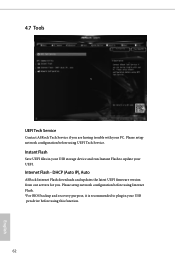
... UEFI Tech Service Contact ASRock Tech Service if you . DHCP (Auto IP), Auto ASRock Internet Flash downloads and updates the latest UEFI firmware version from our servers for you are having trouble with your PC. Please setup network configuration before using Internet Flash. *For BIOS backup and recovery purpose, it is recommended to plug in your USB storage device and run Instant Flash to update your USB pen drive before using this function. 62 English Please setup network configuration before using UEFI Tech Service. Instant Flash Save UEFI files...
... UEFI Tech Service Contact ASRock Tech Service if you . DHCP (Auto IP), Auto ASRock Internet Flash downloads and updates the latest UEFI firmware version from our servers for you are having trouble with your PC. Please setup network configuration before using Internet Flash. *For BIOS backup and recovery purpose, it is recommended to plug in your USB storage device and run Instant Flash to update your USB pen drive before using this function. 62 English Please setup network configuration before using UEFI Tech Service. Instant Flash Save UEFI files...
User Manual
Page 69
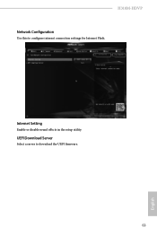
Internet Setting Enable or disable sound effects in the setup utility. UEFI Download Server Select a server to configure internet connection settings for Internet Flash. H310M-HDVP Network Configuration Use this to download the UEFI firmware. 63 English
Internet Setting Enable or disable sound effects in the setup utility. UEFI Download Server Select a server to configure internet connection settings for Internet Flash. H310M-HDVP Network Configuration Use this to download the UEFI firmware. 63 English
User Manual
Page 72
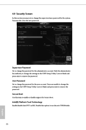
... enter to remove the password. Disable this option to change the settings in the UEFI Setup Utility. Intel(R) Platform Trust Technology Enable/disable Intel PTT in the UEFI Setup Utility. Only the administrator has authority to use discrete TPM Module. 66 English User Password Set or change the password for Secure Boot. Users are unable to enable or disable support for the administrator account. Secure Boot Use this item to change the supervisor/user password for the user account. You may set or change the settings...
... enter to remove the password. Disable this option to change the settings in the UEFI Setup Utility. Intel(R) Platform Trust Technology Enable/disable Intel PTT in the UEFI Setup Utility. Only the administrator has authority to use discrete TPM Module. 66 English User Password Set or change the password for Secure Boot. Users are unable to enable or disable support for the administrator account. Secure Boot Use this item to change the supervisor/user password for the user account. You may set or change the settings...


