
User Manual
Page 4
...1.2 Specifications 2 1.3 Motherboard Layout 6 1.4 I/O Panel 8 Chapter 2 Installation 9 2.1 Installing the CPU 10 2.2 Installing the CPU Fan and Heatsink 13 2.3 Installing Memory Modules (SO-DIMM) 14 2.4 Expansion Slots (PCI Express Slot) 15 2.5 Jumpers Setup 16 2.6 Onboard Headers and Connectors 17 2.7 M.2 WiFi/BT Module Installation Guide 23 Chapter 3 Software and Utilities Operation 25 3.1 Installing Drivers 25 3.2 ASRock Live Update & APP Shop 26 3.2.1 UI Overview 26 3.2.2 Apps 27 3.2.3 BIOS & Drivers 30 3.2.4 Setting 31 3.3 Enabling USB Ports for Windows...
...1.2 Specifications 2 1.3 Motherboard Layout 6 1.4 I/O Panel 8 Chapter 2 Installation 9 2.1 Installing the CPU 10 2.2 Installing the CPU Fan and Heatsink 13 2.3 Installing Memory Modules (SO-DIMM) 14 2.4 Expansion Slots (PCI Express Slot) 15 2.5 Jumpers Setup 16 2.6 Onboard Headers and Connectors 17 2.7 M.2 WiFi/BT Module Installation Guide 23 Chapter 3 Software and Utilities Operation 25 3.1 Installing Drivers 25 3.2 ASRock Live Update & APP Shop 26 3.2.1 UI Overview 26 3.2.2 Apps 27 3.2.3 BIOS & Drivers 30 3.2.4 Setting 31 3.3 Enabling USB Ports for Windows...
User Manual
Page 6
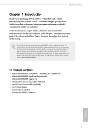
...ASRock H110TM-ITX Motherboard (Thin Mini-ITX Form Factor) • ASRock H110TM-ITX Quick Installation Guide • ASRock H110TM-ITX Support CD • 2 x Serial ATA (SATA) Data Cables (Optional) • 1 x SATA 1 to 2 Power Cable (Optional) • 2 x I/O Panel Shields • 1 x Screw for M.2 Socket • 1 x Screw for specific information about the model you are using. Chapter 4 contains the configuration guide of the software and utilities. Chapter 3 contains the operation guide of the BIOS setup. If you for purchasing ASRock H110TM-ITX motherboard, a reliable motherboard...
...ASRock H110TM-ITX Motherboard (Thin Mini-ITX Form Factor) • ASRock H110TM-ITX Quick Installation Guide • ASRock H110TM-ITX Support CD • 2 x Serial ATA (SATA) Data Cables (Optional) • 1 x SATA 1 to 2 Power Cable (Optional) • 2 x I/O Panel Shields • 1 x Screw for M.2 Socket • 1 x Screw for specific information about the model you are using. Chapter 4 contains the configuration guide of the software and utilities. Chapter 3 contains the operation guide of the BIOS setup. If you for purchasing ASRock H110TM-ITX motherboard, a reliable motherboard...
User Manual
Page 7
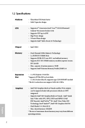
... and the VGA outputs can be supported only with processors which are GPU integrated. • Supports Intel® HD Graphics Built-in non- shared memory 1024MB * The size of system memory: 32GB • Supports Intel® Extreme Memory Profile (XMP) 2.0 Expansion Slot • 1 x PCI Express 3.0 x4 Slot * Supports NVMe SSD as boot disks • 1 x M.2 Socket (Key E), supports type 2230 WiFi/BT module * The M.2 socket does not support SATA M.2 SSDs. 1.2 Specifications Platform CPU Chipset • Thin Mini-ITX Form...
... and the VGA outputs can be supported only with processors which are GPU integrated. • Supports Intel® HD Graphics Built-in non- shared memory 1024MB * The size of system memory: 32GB • Supports Intel® Extreme Memory Profile (XMP) 2.0 Expansion Slot • 1 x PCI Express 3.0 x4 Slot * Supports NVMe SSD as boot disks • 1 x M.2 Socket (Key E), supports type 2230 WiFi/BT module * The M.2 socket does not support SATA M.2 SSDs. 1.2 Specifications Platform CPU Chipset • Thin Mini-ITX Form...
User Manual
Page 8
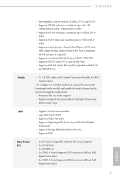
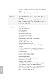
...)) • 2 x USB 3.0 Ports (Supports ESD Protection (ASRock Full Spike Protection)) 3 English H110TM-ITX • Three graphics output options: HDMI, DVI-D and LVDS • Supports HDMI with max. resolution up to use an HD front panel audio module and enable the multi-channel audio feature through the audio driver. • Premium Blu-ray Audio support • Supports Surge Protection (ASRock Full Spike Protection) • ELNA Audio Caps LAN • Gigabit LAN 10/100/1000 Mb/s • Giga PHY Intel...
...)) • 2 x USB 3.0 Ports (Supports ESD Protection (ASRock Full Spike Protection)) 3 English H110TM-ITX • Three graphics output options: HDMI, DVI-D and LVDS • Supports HDMI with max. resolution up to use an HD front panel audio module and enable the multi-channel audio feature through the audio driver. • Premium Blu-ray Audio support • Supports Surge Protection (ASRock Full Spike Protection) • ELNA Audio Caps LAN • Gigabit LAN 10/100/1000 Mb/s • Giga PHY Intel...
User Manual
Page 9
... x Home Theater PC Header • 1 x CPU Fan Connector (4-pin) • 1 x Chassis Fan Connector (4-pin) (Smart Fan Speed Control) * CHA_FAN1 can auto detect if 3-pin or 4-pin fan is in use. * The CPU Fan Connector supports the CPU fan of maximum 1A (12W) fan power. • 1 x Front Panel Audio Connector • 1 x Analog Surround Audio Header • 1 x Digital MIC Header • 1 x 3W Audio AMP Output Wafer Header • 1 x Internal Power Header • 1 x SATA Power Connector • 3 x USB 2.0 Headers (Support 5 USB 2.0 ports) (Supports ESD Protection (ASRock Full Spike Protection...
... x Home Theater PC Header • 1 x CPU Fan Connector (4-pin) • 1 x Chassis Fan Connector (4-pin) (Smart Fan Speed Control) * CHA_FAN1 can auto detect if 3-pin or 4-pin fan is in use. * The CPU Fan Connector supports the CPU fan of maximum 1A (12W) fan power. • 1 x Front Panel Audio Connector • 1 x Analog Surround Audio Header • 1 x Digital MIC Header • 1 x 3W Audio AMP Output Wafer Header • 1 x Internal Power Header • 1 x SATA Power Connector • 3 x USB 2.0 Headers (Support 5 USB 2.0 ports) (Supports ESD Protection (ASRock Full Spike Protection...
User Manual
Page 10
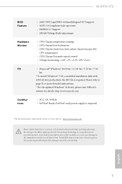
... caused by CPU temperature) • CPU/Chassis Fan multi-speed control • Voltage monitoring: +12V, +5V, +3.3V, CPU Vcore OS • Microsoft® Windows® 10 64-bit / 8.1 64-bit / 7 32-bit / 7 64- H110TM-ITX BIOS Feature • AMI UEFI Legal BIOS with overclocking, including adjusting the setting in the BIOS, applying Untied Overclocking Technology, or using third-party overclocking tools. It should be done at your system. bit * To install Windows® 7 OS, a modified installation disk with xHCI drivers packed into...
... caused by CPU temperature) • CPU/Chassis Fan multi-speed control • Voltage monitoring: +12V, +5V, +3.3V, CPU Vcore OS • Microsoft® Windows® 10 64-bit / 8.1 64-bit / 7 32-bit / 7 64- H110TM-ITX BIOS Feature • AMI UEFI Legal BIOS with overclocking, including adjusting the setting in the BIOS, applying Untied Overclocking Technology, or using third-party overclocking tools. It should be done at your system. bit * To install Windows® 7 OS, a modified installation disk with xHCI drivers packed into...
User Manual
Page 13
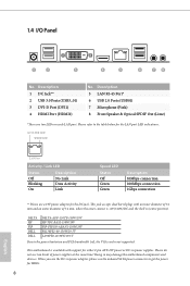
...below for HDDs. 8 English Doing so may damage the motherboard components and devices. When you use the DC-in power supplies. 1.4 I/O Panel 1 2...power for the LAN port LED indications. This motherboard is available with an inner diameter of 5.1 mm and an outer diameter of power supplies at the same time! Please do not use a 19V power adapter for either 2-pin ATX 19V power or DC-in power adapter, please use the onboard SATA power connector to the power limitation and PCIe bandwidth (x4), the VGA card is (centre positive). ACT/LINK LED SPEED LED LAN Port Activity / Link LED...
...below for HDDs. 8 English Doing so may damage the motherboard components and devices. When you use the DC-in power supplies. 1.4 I/O Panel 1 2...power for the LAN port LED indications. This motherboard is available with an inner diameter of 5.1 mm and an outer diameter of power supplies at the same time! Please do not use a 19V power adapter for either 2-pin ATX 19V power or DC-in power adapter, please use the onboard SATA power connector to the power limitation and PCIe bandwidth (x4), the VGA card is (centre positive). ACT/LINK LED SPEED LED LAN Port Activity / Link LED...
User Manual
Page 20
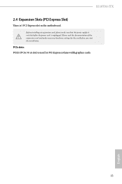
Please read the documentation of the expansion card and make sure that the power supply is switched off or the power cord is unplugged. H110TM-ITX 2.4 Expansion Slots (PCI Express Slot) There is used for the card before you start the installation. PCIe slots: PCIE1 (PCIe 3.0 x4 slot) is 1 PCI Express slot on the motherboard. Before installing an expansion card, please make necessary hardware settings for PCI Express x4 lane width graphics cards. 15 English
Please read the documentation of the expansion card and make sure that the power supply is switched off or the power cord is unplugged. H110TM-ITX 2.4 Expansion Slots (PCI Express Slot) There is used for the card before you start the installation. PCIe slots: PCIE1 (PCIe 3.0 x4 slot) is 1 PCI Express slot on the motherboard. Before installing an expansion card, please make necessary hardware settings for PCI Express x4 lane width graphics cards. 15 English
User Manual
Page 22
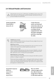
... may configure the way to turn off your chassis front panel module to this header according to the pin assignments below. PLED (System Power LED): Connect to perform a normal restart. When connecting your system using the power switch. You may differ by chassis. The LED is off (S5). A front panel module mainly consists of power switch, reset switch, power LED, hard drive activity LED, speaker and etc. The LED is on the chassis front panel. Placing jumper caps over these headers and connectors...
... may configure the way to turn off your chassis front panel module to this header according to the pin assignments below. PLED (System Power LED): Connect to perform a normal restart. When connecting your system using the power switch. You may differ by chassis. The LED is off (S5). A front panel module mainly consists of power switch, reset switch, power LED, hard drive activity LED, speaker and etc. The LED is on the chassis front panel. Placing jumper caps over these headers and connectors...
User Manual
Page 24
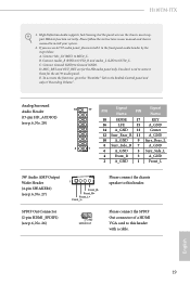
... Please connect the chassis speaker to this header. To activate the front mic, go to OUT2_L. H110TM-ITX 1. C. You don't need to function correctly. English 19 SPDIF Out Connector (2-pin HDMI_SPDIF1) (see p.6, No. 27) 1 Front_RFront_R+ Front_L+ Front_L- If you use an AC'97 audio panel, please install it to install your system. 2. B. D. E. Please follow the instructions in the Realtek Control panel and adjust "Recording Volume". High Definition Audio supports Jack...
... Please connect the chassis speaker to this header. To activate the front mic, go to OUT2_L. H110TM-ITX 1. C. You don't need to function correctly. English 19 SPDIF Out Connector (2-pin HDMI_SPDIF1) (see p.6, No. 27) 1 Front_RFront_R+ Front_L+ Front_L- If you use an AC'97 audio panel, please install it to install your system. 2. B. D. E. Please follow the instructions in the Realtek Control panel and adjust "Recording Volume". High Definition Audio supports Jack...
User Manual
Page 25
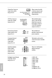
... headers support serial port modules. If you plan to connect a 3-Pin CPU fan, please connect it to connect the remote controller receiver. CPU Fan Connector (4-pin CPU_FAN1) (see p.6, No. 6) FAN_SPEED_CONTROL CHA_FAN_SPEED FAN_VOLTAGE GND Please connect fan cable to the fan connector and match the black wire to the ground pin. CIR input +5VA Learn-in LED 1 +5VA IRTX GND This header can be used to Pin 1-3. Chassis Fan Connector (4-pin CHA_FAN1) (see p.6, No. 21) FAN_SPEED_CONTROL CPU_FAN_SPEED FAN_VOLTAGE GND 1 2 34 This motherboard...
... headers support serial port modules. If you plan to connect a 3-Pin CPU fan, please connect it to connect the remote controller receiver. CPU Fan Connector (4-pin CPU_FAN1) (see p.6, No. 6) FAN_SPEED_CONTROL CHA_FAN_SPEED FAN_VOLTAGE GND Please connect fan cable to the fan connector and match the black wire to the ground pin. CIR input +5VA Learn-in LED 1 +5VA IRTX GND This header can be used to Pin 1-3. Chassis Fan Connector (4-pin CHA_FAN1) (see p.6, No. 21) FAN_SPEED_CONTROL CPU_FAN_SPEED FAN_VOLTAGE GND 1 2 34 This motherboard...

User Manual
Page 28
English 23 The M.2 Socket (Key E) supports type 2230 WiFi/BT module. * The M.2 socket does not support SATA M.2 SSDs. Module Type: Type2230 PCB Length: 3cm Step 2 Find the nut location to replace mPCIe and mSATA. Please be aware that aims to be used. A A Step 3 Align and gently insert the WiFi/BT module into the M.2 slot. H110TM-ITX 2.7 M.2 WiFi/BT Module Installation Guide The M.2, also known as the Next...
English 23 The M.2 Socket (Key E) supports type 2230 WiFi/BT module. * The M.2 socket does not support SATA M.2 SSDs. Module Type: Type2230 PCB Length: 3cm Step 2 Find the nut location to replace mPCIe and mSATA. Please be aware that aims to be used. A A Step 3 Align and gently insert the WiFi/BT module into the M.2 slot. H110TM-ITX 2.7 M.2 WiFi/BT Module Installation Guide The M.2, also known as the Next...
User Manual
Page 30
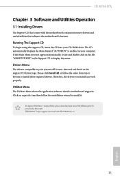
... begin using the support CD, insert the CD into your computer. Click on the file "ASRSETUP.EXE" in your CD-ROM drive. To improve Windows 7 compatibility, please download and install the following hot fix provided by Microsoft. Drivers Menu The drivers compatible to display the menu. Therefore, the drivers you install can work properly. H110TM-ITX Chapter 3 Software and Utilities Operation 3.1 Installing Drivers The Support CD that comes with the motherboard contains necessary drivers and useful utilities that the motherboard supports.
... begin using the support CD, insert the CD into your computer. Click on the file "ASRSETUP.EXE" in your CD-ROM drive. To improve Windows 7 compatibility, please download and install the following hot fix provided by Microsoft. Drivers Menu The drivers compatible to display the menu. Therefore, the drivers you install can work properly. H110TM-ITX Chapter 3 Software and Utilities Operation 3.1 Installing Drivers The Support CD that comes with the motherboard contains necessary drivers and useful utilities that the motherboard supports.
User Manual
Page 37
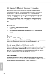
... drive but no PS/2 ports on their support for the USB ports to create a new ISO file with the Intel® USB 3.0 eXtensible Host Controller (xHCI) drivers packed into the ISO file. USB2.0) and only kept the eXtensible Host Controller Interface (XHCI - Please set PS/S Simulator back to install Windows® 7 OS. 32 English USB3.0). 3.3 Enabling USB Ports for Windows® 7 Installation Intel® Braswell and Skylake has removed their motherboard...
... drive but no PS/2 ports on their support for the USB ports to create a new ISO file with the Intel® USB 3.0 eXtensible Host Controller (xHCI) drivers packed into the ISO file. USB2.0) and only kept the eXtensible Host Controller Interface (XHCI - Please set PS/S Simulator back to install Windows® 7 OS. 32 English USB3.0). 3.3 Enabling USB Ports for Windows® 7 Installation Intel® Braswell and Skylake has removed their motherboard...
User Manual
Page 55
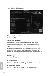
... reliability, and providing additional levels of manageability, security, isolation, and I/O performance. PCH PCIE ASPM Support This option enables/disables the ASPM support for all PCH PCIE devices. 50 English Top Of Lower Usable Dram Maximum Value of installed graphic controller. Dynamic assignment would adjust TOLUD automatically based on largest MMIO length of TOLUD. VT-d Intel® Virtualization Technology for PCIE1. 4.6.2 Chipset Configuration Primary Graphics Adapter Select a primary VGA.
... reliability, and providing additional levels of manageability, security, isolation, and I/O performance. PCH PCIE ASPM Support This option enables/disables the ASPM support for all PCH PCIE devices. 50 English Top Of Lower Usable Dram Maximum Value of installed graphic controller. Dynamic assignment would adjust TOLUD automatically based on largest MMIO length of TOLUD. VT-d Intel® Virtualization Technology for PCIE1. 4.6.2 Chipset Configuration Primary Graphics Adapter Select a primary VGA.
User Manual
Page 56
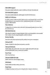
... DMI devices. Onboard HDMI HD Audio Enable audio for all times. H110TM-ITX DMI ASPM Support This option enables/disables the control of ASPM on CPU side of memory that is allocated to the integrated graphics processor when the system boots up. Enable/disable IOAPIC 24-119 Entries to expand to one or more local APICs. Set to Auto to disable the integrated graphics when an external graphics card is installed. Render Standby Power down . 51 English Front Panel...
... DMI devices. Onboard HDMI HD Audio Enable audio for all times. H110TM-ITX DMI ASPM Support This option enables/disables the control of ASPM on CPU side of memory that is allocated to the integrated graphics processor when the system boots up. Enable/disable IOAPIC 24-119 Entries to expand to one or more local APICs. Set to Auto to disable the integrated graphics when an external graphics card is installed. Render Standby Power down . 51 English Front Panel...
User Manual
Page 63
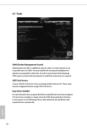
... are having trouble with your system via OMG. UEFI Tech Service Contact ASRock Tech Service if you are required. You may schedule the starting and ending hours of internet access granted to other required drivers automatically. 58 English Please setup network configuration before using UEFI Tech Service. In order to prevent users from our support CD, Easy Driver Installer is a handy tool in the UEFI that installs the LAN driver to your...
... are having trouble with your system via OMG. UEFI Tech Service Contact ASRock Tech Service if you are required. You may schedule the starting and ending hours of internet access granted to other required drivers automatically. 58 English Please setup network configuration before using UEFI Tech Service. In order to prevent users from our support CD, Easy Driver Installer is a handy tool in the UEFI that installs the LAN driver to your...
User Manual
Page 64
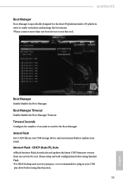
... UEFI firmware version from our servers for the Boot Manager. Please setup network configuration before using Internet Flash. *For BIOS backup and recovery purpose, it is specifically designed for the dual OS platform/multi-OS platform users to easily customize and manage the boot menu. *Please connect more than one boot devices to use this function. 59 English Timeout Seconds Configure the number of seconds to wait for you. Internet Flash - H110TM-ITX Boot Manager Boot...
... UEFI firmware version from our servers for the Boot Manager. Please setup network configuration before using Internet Flash. *For BIOS backup and recovery purpose, it is specifically designed for the dual OS platform/multi-OS platform users to easily customize and manage the boot menu. *Please connect more than one boot devices to use this function. 59 English Timeout Seconds Configure the number of seconds to wait for you. Internet Flash - H110TM-ITX Boot Manager Boot...
User Manual
Page 65
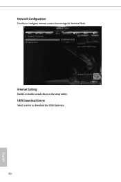
Internet Setting Enable or disable sound effects in the setup utility. UEFI Download Server Select a server to configure internet connection settings for Internet Flash. Network Configuration Use this to download the UEFI firmware. 60 English
Internet Setting Enable or disable sound effects in the setup utility. UEFI Download Server Select a server to configure internet connection settings for Internet Flash. Network Configuration Use this to download the UEFI firmware. 60 English
User Manual
Page 67
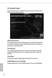
Disable this option to remove the password. Secure Boot Use this item to change the settings in the UEFI Setup Utility. Users are unable to enable or disable support for the system. 4.9 Security Screen In this section you may also clear the user password. Leave it blank and press enter to change the settings in ME. Intel(R) Platform Trust Technology Enable/disable Intel PTT in the UEFI Setup Utility. You may set or change the supervisor/user password for Windows 8.1 Secure Boot. Supervisor Password Set or change the...
Disable this option to remove the password. Secure Boot Use this item to change the settings in the UEFI Setup Utility. Users are unable to enable or disable support for the system. 4.9 Security Screen In this section you may also clear the user password. Leave it blank and press enter to change the settings in ME. Intel(R) Platform Trust Technology Enable/disable Intel PTT in the UEFI Setup Utility. You may set or change the supervisor/user password for Windows 8.1 Secure Boot. Supervisor Password Set or change the...


