
User Manual
Page 2
... in California, USA, please follow the related regulations in Perchlorate Best Management Practices (BMP) regulations passed by ASRock. ASRock assumes no event shall ASRock, its directors, officers, employees, or agents be constructed as a commitment by the California Legislature. With respect... of merchantability or fitness for any interference received, including interference that may not cause harmful interference, and (2) this motherboard contains Perchlorate, a toxic substance controlled in advance. All rights reserved. Copyright Notice: No part of this documentation may...
... in California, USA, please follow the related regulations in Perchlorate Best Management Practices (BMP) regulations passed by ASRock. ASRock assumes no event shall ASRock, its directors, officers, employees, or agents be constructed as a commitment by the California Legislature. With respect... of merchantability or fitness for any interference received, including interference that may not cause harmful interference, and (2) this motherboard contains Perchlorate, a toxic substance controlled in advance. All rights reserved. Copyright Notice: No part of this documentation may...
User Manual
Page 4
... 1 1.1 Package Contents 1 1.2 Specifications 2 1.3 Motherboard Layout 6 1.4 I/O Panel 8 Chapter 2 Installation 10 2.1 Installing the CPU 11 2.2 Installing the CPU Fan and Heatsink 14 2.3 Installing Memory Modules (DIMM) 15 2.4 Expansion Slots (PCI Express Slots) 17 2.5 Jumpers Setup 18 2.6 Onboard Headers and Connectors 19 Chapter 3 Software and Utilities Operation 23 3.1 Installing Drivers 23 3.2 ASRock Live Update & APP...
... 1 1.1 Package Contents 1 1.2 Specifications 2 1.3 Motherboard Layout 6 1.4 I/O Panel 8 Chapter 2 Installation 10 2.1 Installing the CPU 11 2.2 Installing the CPU Fan and Heatsink 14 2.3 Installing Memory Modules (DIMM) 15 2.4 Expansion Slots (PCI Express Slots) 17 2.5 Jumpers Setup 18 2.6 Onboard Headers and Connectors 19 Chapter 3 Software and Utilities Operation 23 3.1 Installing Drivers 23 3.2 ASRock Live Update & APP...
User Manual
Page 6
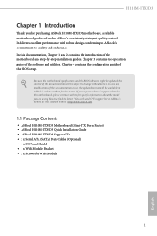
... to quality and endurance. In this documentation occur, the updated version will be available on ASRock's website as well. ASRock website http://www.asrock.com. 1.1 Package Contents • ASRock H110M-ITX/D3 Motherboard (Mini-ITX Form Factor) • ASRock H110M-ITX/D3 Quick Installation Guide • ASRock H110M-ITX/D3 Support CD • 2 x Serial ATA (SATA) Data Cables (Optional) • 1 x I/O Panel Shield • 1 x WiFi...
... to quality and endurance. In this documentation occur, the updated version will be available on ASRock's website as well. ASRock website http://www.asrock.com. 1.1 Package Contents • ASRock H110M-ITX/D3 Motherboard (Mini-ITX Form Factor) • ASRock H110M-ITX/D3 Quick Installation Guide • ASRock H110M-ITX/D3 Support CD • 2 x Serial ATA (SATA) Data Cables (Optional) • 1 x I/O Panel Shield • 1 x WiFi...
User Manual
Page 11
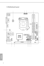
1.3 Motherboard Layout CHA_FAN1 CPU_FAN1 USB 2.0 T: USB1 B: USB2 PS2 Keyboard /Mouse DVI1 HDMI1 AT X P W R 1 DDR3_A1 (64 bit, 240-pin module) DDR3_B1 (64 bit, 240-pin module) ATX12V1 RoHS USB11 1 USB 3.0 T: USB3 B: USB4 Top: RJ-45 CMOS Battery USB 2.0 T: USB5 B: USB6 HD_AUDIO1 1 CI1 1 Intel H110 SATA3_3 SATA3_2 SATA3_1 SATA3_0 MINI_PCIE1 128Mb BIOS PCIE1 H110M-ITX/D3 1 USB_9_10 1 SPEAKER1 1 1 PANEL1 CLRMOS1 1 Top: LINE IN Center: FRONT Bottom: MIC IN USB3_7_8 TPMS1 PLED PWRBTN HDLED RESET English 6
1.3 Motherboard Layout CHA_FAN1 CPU_FAN1 USB 2.0 T: USB1 B: USB2 PS2 Keyboard /Mouse DVI1 HDMI1 AT X P W R 1 DDR3_A1 (64 bit, 240-pin module) DDR3_B1 (64 bit, 240-pin module) ATX12V1 RoHS USB11 1 USB 3.0 T: USB3 B: USB4 Top: RJ-45 CMOS Battery USB 2.0 T: USB5 B: USB6 HD_AUDIO1 1 CI1 1 Intel H110 SATA3_3 SATA3_2 SATA3_1 SATA3_0 MINI_PCIE1 128Mb BIOS PCIE1 H110M-ITX/D3 1 USB_9_10 1 SPEAKER1 1 1 PANEL1 CLRMOS1 1 Top: LINE IN Center: FRONT Bottom: MIC IN USB3_7_8 TPMS1 PLED PWRBTN HDLED RESET English 6
User Manual
Page 15
... Installation This is a Mini-ITX form factor motherboard. Pre-installation Precautions Take note of your motherboard directly on a grounded anti-static pad or in the bag that the motherboard fits into it. Doing so may cause physical injuries and damages to motherboard components. • In order... static electricity to the chassis, please do not overtighten the screws! Before you install the motherboard, study the configuration of the following precautions before you uninstall any motherboard settings. • Make sure to ensure that comes with the components. • When ...
... Installation This is a Mini-ITX form factor motherboard. Pre-installation Precautions Take note of your motherboard directly on a grounded anti-static pad or in the bag that the motherboard fits into it. Doing so may cause physical injuries and damages to motherboard components. • In order... static electricity to the chassis, please do not overtighten the screws! Before you install the motherboard, study the configuration of the following precautions before you uninstall any motherboard settings. • Make sure to ensure that comes with the components. • When ...
User Manual
Page 18
The cover must be placed if you wish to return the motherboard for after service. 13 English H110M-ITX/D3 Please save and replace the cover if the processor is removed.
The cover must be placed if you wish to return the motherboard for after service. 13 English H110M-ITX/D3 Please save and replace the cover if the processor is removed.
User Manual
Page 20
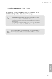
...unable to install identical (the same brand, speed, size and chip-type) DDR3/DDR3L DIMM pairs. 2. otherwise, this motherboard and DIMM may be damaged. H110M-ITX/D3 2.3 Installing Memory Modules (DIMM) This motherboard provides two 240-pin DDR3/DDR3L (Double Data Rate 3) DIMM slots, and supports Dual Channel Memory Technology. 1. For... the DIMM into a DDR3/DDR3L slot; The DIMM only fits in one memory module installed. 3. It will cause permanent damage to the motherboard and the DIMM if you always need to activate Dual Channel Memory Technology with only one correct orientation.
...unable to install identical (the same brand, speed, size and chip-type) DDR3/DDR3L DIMM pairs. 2. otherwise, this motherboard and DIMM may be damaged. H110M-ITX/D3 2.3 Installing Memory Modules (DIMM) This motherboard provides two 240-pin DDR3/DDR3L (Double Data Rate 3) DIMM slots, and supports Dual Channel Memory Technology. 1. For... the DIMM into a DDR3/DDR3L slot; The DIMM only fits in one memory module installed. 3. It will cause permanent damage to the motherboard and the DIMM if you always need to activate Dual Channel Memory Technology with only one correct orientation.
User Manual
Page 22
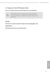
Please read the documentation of the expansion card and make sure that the power supply is switched off or the power cord is 1 PCI Express slot and 1 mini-PCI Express slot on the motherboard. mini-PCIe slot: MPCIE1 (mini-PCIe slot) is used for the card before you start the installation. Before installing an expansion card, please make necessary hardware settings for WiFi module. 17 English H110M-ITX/D3 2.4 Expansion Slots (PCI Express Slots) There is unplugged. PCIe slot: PCIE1 (PCIe 3.0 x16 slot) is used for PCI Express x16 lane width graphics cards.
Please read the documentation of the expansion card and make sure that the power supply is switched off or the power cord is 1 PCI Express slot and 1 mini-PCI Express slot on the motherboard. mini-PCIe slot: MPCIE1 (mini-PCIe slot) is used for the card before you start the installation. Before installing an expansion card, please make necessary hardware settings for WiFi module. 17 English H110M-ITX/D3 2.4 Expansion Slots (PCI Express Slots) There is unplugged. PCIe slot: PCIE1 (PCIe 3.0 x16 slot) is used for PCI Express x16 lane width graphics cards.
User Manual
Page 24
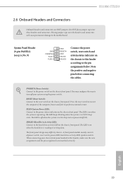
...power switch on the chassis front panel. Placing jumper caps over these headers and connectors. PWRBTN (Power Switch): Connect to the motherboard. Press the reset switch to restart the computer if the computer freezes and fails to the hard drive activity LED on the... HDLEDHDLED+ 1 Connect the power switch, reset switch and system status indicator on the chassis front panel. You may differ by chassis. H110M-ITX/D3 2.6 Onboard Headers and Connectors Onboard headers and connectors are matched correctly. Note the positive and negative pins before connecting the cables. The...
...power switch on the chassis front panel. Placing jumper caps over these headers and connectors. PWRBTN (Power Switch): Connect to the motherboard. Press the reset switch to restart the computer if the computer freezes and fails to the hard drive activity LED on the... HDLEDHDLED+ 1 Connect the power switch, reset switch and system status indicator on the chassis front panel. You may differ by chassis. H110M-ITX/D3 2.6 Onboard Headers and Connectors Onboard headers and connectors are matched correctly. Note the positive and negative pins before connecting the cables. The...
User Manual
Page 25
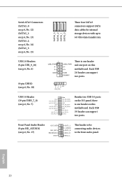
... IntA_PA_SSRXIntA_PA_SSRX+ GND IntA_PA_SSTXIntA_PA_SSTX+ GND IntA_PA_DIntA_PA_D+ Vbus IntA_PB_SSRXIntA_PB_SSRX+ GND IntA_PB_SSTXIntA_PB_SSTX+ GND IntA_PB_DIntA_PB_D+ Dummy 1 Besides two USB 3.0 ports on the I/O panel, there is one port on this motherboard. Serial ATA3 Connectors (SATA3_0: see p.6, No. 12) (SATA3_1: see p.6, No. 13) (SATA3_2: see p.6, No. 14) (SATA3_3: see p.6, No. 15) SATA3_3 SATA3_2 SATA3_1 ... 6) (4-pin USB11) (see p.6, No. 17) OUT_RET MIC_RET PRESENCE# GND OUT2_L J_SENSE OUT2_R MIC2_R MIC2_L 1 This header is one header and one header on this motherboard.
... IntA_PA_SSRXIntA_PA_SSRX+ GND IntA_PA_SSTXIntA_PA_SSTX+ GND IntA_PA_DIntA_PA_D+ Vbus IntA_PB_SSRXIntA_PB_SSRX+ GND IntA_PB_SSTXIntA_PB_SSTX+ GND IntA_PB_DIntA_PB_D+ Dummy 1 Besides two USB 3.0 ports on the I/O panel, there is one port on this motherboard. Serial ATA3 Connectors (SATA3_0: see p.6, No. 12) (SATA3_1: see p.6, No. 13) (SATA3_2: see p.6, No. 14) (SATA3_3: see p.6, No. 15) SATA3_3 SATA3_2 SATA3_1 ... 6) (4-pin USB11) (see p.6, No. 17) OUT_RET MIC_RET PRESENCE# GND OUT2_L J_SENSE OUT2_R MIC2_R MIC2_L 1 This header is one header and one header on this motherboard.

User Manual
Page 26
... SPEAKER 1 +5V DUMMY Please connect the chassis speaker to the ground pin. Chassis Fan Connector (4-pin CHA_FAN1) (see p.6, No. 3) 4 3 21 GND FAN_VOLTAGE CPU_FAN_SPEED FAN_SPEED_CONTROL This motherboard provides a 4-Pin CPU fan (Quiet Fan) connector. English 21 If you plan to connect a 3-Pin CPU fan, please connect it to OUT2_L. Connect Audio_R (RIN... panel wire on the chassis must support HDA to install your system. 2. Please follow the instructions in the Realtek Control panel and adjust "Recording Volume". B. H110M-ITX/D3 1.
... SPEAKER 1 +5V DUMMY Please connect the chassis speaker to the ground pin. Chassis Fan Connector (4-pin CHA_FAN1) (see p.6, No. 3) 4 3 21 GND FAN_VOLTAGE CPU_FAN_SPEED FAN_SPEED_CONTROL This motherboard provides a 4-Pin CPU fan (Quiet Fan) connector. English 21 If you plan to connect a 3-Pin CPU fan, please connect it to OUT2_L. Connect Audio_R (RIN... panel wire on the chassis must support HDA to install your system. 2. Please follow the instructions in the Realtek Control panel and adjust "Recording Volume". B. H110M-ITX/D3 1.
User Manual
Page 27
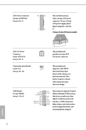
...Pin 1 and Pin 11. ATX Power Connector (20-pin ATXPWR1) (see p.6, No. 8) This motherboard provides an 4-pin ATX 12V power connector. 1 GND Signal This motherboard supports CASE OPEN detection feature that detects if the chassis cove has been removed. PCIRST# FRAME PCICLK This...1) Chassis Intrusion Header (2-pin CI1) (see p.6, No. 16) TPM Header (17-pin TPMS1) (see p.6, No. 5) 10 12 1 11 This motherboard provides a 20-pin ATX power connector. A TPM system also helps enhance network security, protects digital identities, and ensures platform integrity. 22 English This feature ...
...Pin 1 and Pin 11. ATX Power Connector (20-pin ATXPWR1) (see p.6, No. 8) This motherboard provides an 4-pin ATX 12V power connector. 1 GND Signal This motherboard supports CASE OPEN detection feature that detects if the chassis cove has been removed. PCIRST# FRAME PCICLK This...1) Chassis Intrusion Header (2-pin CI1) (see p.6, No. 16) TPM Header (17-pin TPMS1) (see p.6, No. 5) 10 12 1 11 This motherboard provides a 20-pin ATX power connector. A TPM system also helps enhance network security, protects digital identities, and ensures platform integrity. 22 English This feature ...
User Manual
Page 28
... and install the following hot fix provided by Microsoft. Utilities Menu The Utilities Menu shows the application software that enhance the motherboard's features. "KB2720599": http://support.microsoft.com/kb/2720599/en-us 23 English Running The Support CD To begin using the...or follow the installation wizard to display the menu. H110M-ITX/D3 Chapter 3 Software and Utilities Operation 3.1 Installing Drivers The Support CD that comes with the motherboard contains necessary drivers and useful utilities that the motherboard supports. Drivers Menu The drivers compatible to install those ...
... and install the following hot fix provided by Microsoft. Utilities Menu The Utilities Menu shows the application software that enhance the motherboard's features. "KB2720599": http://support.microsoft.com/kb/2720599/en-us 23 English Running The Support CD To begin using the...or follow the installation wizard to display the menu. H110M-ITX/D3 Chapter 3 Software and Utilities Operation 3.1 Installing Drivers The Support CD that comes with the motherboard contains necessary drivers and useful utilities that the motherboard supports. Drivers Menu The drivers compatible to install those ...
User Manual
Page 29
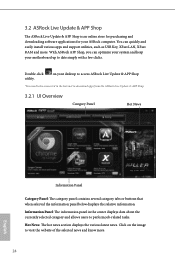
... Internet to visit the website of the selected news and know more . You can optimize your system and keep your motherboard up to perform job-related tasks. With ASRock APP Shop, you can quickly and easily install various apps and support utilities, such as USB Key, XFast LAN, ... RAM and more . 24 English Hot News: The hot news section displays the various latest news. Click on your ASRock computer. on the image to download apps from the ASRock Live Update & APP Shop. 3.2.1 UI Overview Category Panel Hot News Information Panel Category Panel: The category panel contains ...
... Internet to visit the website of the selected news and know more . You can optimize your system and keep your motherboard up to perform job-related tasks. With ASRock APP Shop, you can quickly and easily install various apps and support utilities, such as USB Key, XFast LAN, ... RAM and more . 24 English Hot News: The hot news section displays the various latest news. Click on your ASRock computer. on the image to download apps from the ASRock Live Update & APP Shop. 3.2.1 UI Overview Category Panel Hot News Information Panel Category Panel: The category panel contains ...
User Manual
Page 35
... Interface (EHCI - Requirements • A Windows® 7 installation disk or USB drive • USB 3.0 drivers (included in the ASRock Support CD or website) • A Windows® PC • Win7 USB Patcher (included in the ASRock Support CD or website) Scenarios You have an ODD and PS/2 ports: If there is not included in... PS/S Simulator back to install Windows® 7 OS. 30 English 3.3 Enabling USB Ports for Windows® 7 Installation Intel® Braswell and Skylake has removed their motherboard won't work.
... Interface (EHCI - Requirements • A Windows® 7 installation disk or USB drive • USB 3.0 drivers (included in the ASRock Support CD or website) • A Windows® PC • Win7 USB Patcher (included in the ASRock Support CD or website) Scenarios You have an ODD and PS/2 ports: If there is not included in... PS/S Simulator back to install Windows® 7 OS. 30 English 3.3 Enabling USB Ports for Windows® 7 Installation Intel® Braswell and Skylake has removed their motherboard won't work.
User Manual
Page 43
... to CAS# Delay : The number of clock cycles required between a bank active command and issuing the precharge command. DRAM Frequency If [Auto] is selected, the motherboard will be issued. Secondary Timing 38 English Primary Timing CAS# Latency (tCL) The time between when a memory chip is selected, the corresponding DRAM and BCLK...
... to CAS# Delay : The number of clock cycles required between a bank active command and issuing the precharge command. DRAM Frequency If [Auto] is selected, the motherboard will be issued. Secondary Timing 38 English Primary Timing CAS# Latency (tCL) The time between when a memory chip is selected, the corresponding DRAM and BCLK...
User Manual
Page 64
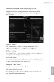
H110M-ITX/D3 4.6 Hardware Health Event Monitoring Screen This section allows you to set 5 CPU temperatures and assign a respective fan speed for each temperature. Chassis Fan 1 Temp Source Select a fan temperature source for each temperature. Over Temperature Protection When Over Temperature Protection is enabled, the system automatically shuts down when the motherboard is overheated... fan speed for CPU Fans 1, or choose Customize to monitor the status of the hardware on your system, including the parameters of the CPU temperature, motherboard temperature, fan speed and voltage.
H110M-ITX/D3 4.6 Hardware Health Event Monitoring Screen This section allows you to set 5 CPU temperatures and assign a respective fan speed for each temperature. Chassis Fan 1 Temp Source Select a fan temperature source for each temperature. Over Temperature Protection When Over Temperature Protection is enabled, the system automatically shuts down when the motherboard is overheated... fan speed for CPU Fans 1, or choose Customize to monitor the status of the hardware on your system, including the parameters of the CPU temperature, motherboard temperature, fan speed and voltage.

