

User Manual
Page 4
... 1 1.2 Specifications 2 1.3 Motherboard Layout 7 1.4 I/O Panel 12 Chapter 2 Installation 17 2.1 Installing the CPU 18 2.2 Installing the CPU Fan and Heatsink 21 2.3 Installing Memory Modules (DIMM) 22 2.4 Expansion Slots (PCI Express Slots) 24 2.5 Onboard Headers and Connectors 25 Chapter 3 Software and Utilities Operation 29 3.1 Installing Drivers 29 3.2 ASRock Live Update & APP Shop 30 3.2.1 UI Overview 30 3.2.2 Apps 31 3.2.3 BIOS & Drivers 34 3.2.4 Setting 35 3.3 Enabling USB Ports for Windows® 7 Installation 36 Chapter 4 UEFI SETUP UTILITY 39...
... 1 1.2 Specifications 2 1.3 Motherboard Layout 7 1.4 I/O Panel 12 Chapter 2 Installation 17 2.1 Installing the CPU 18 2.2 Installing the CPU Fan and Heatsink 21 2.3 Installing Memory Modules (DIMM) 22 2.4 Expansion Slots (PCI Express Slots) 24 2.5 Onboard Headers and Connectors 25 Chapter 3 Software and Utilities Operation 29 3.1 Installing Drivers 29 3.2 ASRock Live Update & APP Shop 30 3.2.1 UI Overview 30 3.2.2 Apps 31 3.2.3 BIOS & Drivers 34 3.2.4 Setting 35 3.3 Enabling USB Ports for Windows® 7 Installation 36 Chapter 4 UEFI SETUP UTILITY 39...

User Manual
Page 6
...-HDV R3.0 / H110M-HDS R3.0 / H110M-DVS R3.0 / H110M-DGS R3.0 Quick Installation Guide • ASRock H110M-HDV R3.0 / H110M-HDS R3.0 / H110M-DVS R3.0 / H110M-DGS R3.0 Support CD • 2 x Serial ATA (SATA) Data Cables (Optional) • 1 x I/O Panel Shield 1 English You may find the latest VGA cards and CPU support list on ASRock's website without notice. H110M-HDV R3.0 / H110M-HDS R3.0 / H110M-DVS R3.0 / H110M-DGS R3.0 Chapter 1 Introduction Thank you for specific information about the model you require technical support related to change without further notice. In this motherboard...
...-HDV R3.0 / H110M-HDS R3.0 / H110M-DVS R3.0 / H110M-DGS R3.0 Quick Installation Guide • ASRock H110M-HDV R3.0 / H110M-HDS R3.0 / H110M-DVS R3.0 / H110M-DGS R3.0 Support CD • 2 x Serial ATA (SATA) Data Cables (Optional) • 1 x I/O Panel Shield 1 English You may find the latest VGA cards and CPU support list on ASRock's website without notice. H110M-HDV R3.0 / H110M-HDS R3.0 / H110M-DVS R3.0 / H110M-DGS R3.0 Chapter 1 Introduction Thank you for specific information about the model you require technical support related to change without further notice. In this motherboard...

User Manual
Page 9
... and enable the multi-channel audio feature through the audio driver. • Supports Surge Protection (ASRock Full Spike Protection) • ELNA Audio Caps LAN • PCIE x1 Gigabit LAN 10/100/1000 Mb/s • Realtek RTL8111C • Supports Wake-On-LAN • Supports Lightning/ESD Protection (ASRock Full Spike Protection) • Supports LAN Cable Detection • Supports PXE Rear Panel I/O • 1 x PS/2 Mouse Port • 1 x PS/2 Keyboard Port • 4 x USB 2.0 Ports (Supports ESD Protection (ASRock Full Spike Protection))* * ACPI wake...
... and enable the multi-channel audio feature through the audio driver. • Supports Surge Protection (ASRock Full Spike Protection) • ELNA Audio Caps LAN • PCIE x1 Gigabit LAN 10/100/1000 Mb/s • Realtek RTL8111C • Supports Wake-On-LAN • Supports Lightning/ESD Protection (ASRock Full Spike Protection) • Supports LAN Cable Detection • Supports PXE Rear Panel I/O • 1 x PS/2 Mouse Port • 1 x PS/2 Keyboard Port • 4 x USB 2.0 Ports (Supports ESD Protection (ASRock Full Spike Protection))* * ACPI wake...
User Manual
Page 10
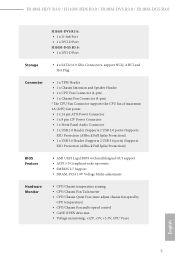
... 24 pin ATX Power Connector • 1 x 8 pin 12V Power Connector • 1 x Front Panel Audio Connector • 1 x USB 2.0 Header (Supports 2 USB 2.0 ports) (Supports ESD Protection (ASRock Full Spike Protection)) • 1 x USB 3.0 Header (Supports 2 USB 3.0 ports) (Supports ESD Protection (ASRock Full Spike Protection)) BIOS Feature • AMI UEFI Legal BIOS with multilingual GUI support • ACPI 5.0 Compliant wake up events • SMBIOS 2.7 Support • DRAM, PCH 1.0V Voltage Multi-adjustment Hardware Monitor • CPU/Chassis temperature sensing • CPU/Chassis Fan...
... 24 pin ATX Power Connector • 1 x 8 pin 12V Power Connector • 1 x Front Panel Audio Connector • 1 x USB 2.0 Header (Supports 2 USB 2.0 ports) (Supports ESD Protection (ASRock Full Spike Protection)) • 1 x USB 3.0 Header (Supports 2 USB 3.0 ports) (Supports ESD Protection (ASRock Full Spike Protection)) BIOS Feature • AMI UEFI Legal BIOS with multilingual GUI support • ACPI 5.0 Compliant wake up events • SMBIOS 2.7 Support • DRAM, PCH 1.0V Voltage Multi-adjustment Hardware Monitor • CPU/Chassis temperature sensing • CPU/Chassis Fan...

User Manual
Page 16
Description 1 ATX 12V Power Connector (ATX12V1) 2 CPU Fan Connector (CPU_FAN1) 3 2 x 288-pin DDR4 DIMM Slots (DDR4_A1, DDR4_B1) 4 Chassis Fan Connector (CHA_FAN1) 5 ATX Power Connector (ATXPWR1) 6 SATA3 Connectors (SATA3_2_3) 7 SATA3 Connectors (SATA3_0_1) 8 USB 3.0 Header (USB3_3_4) 9 USB 2.0 Header (USB_4_5) 10 System Panel Header (PANEL1) 11 Chassis Intrusion and Speaker Header (SPK_CI1) 12 TPM Header (TPMS1) 13 Front Panel Audio Header (HD_AUDIO1) 11 English H110M-HDV R3.0 / H110M-HDS R3.0 / H110M-DVS R3.0 / H110M-DGS R3.0 No.
Description 1 ATX 12V Power Connector (ATX12V1) 2 CPU Fan Connector (CPU_FAN1) 3 2 x 288-pin DDR4 DIMM Slots (DDR4_A1, DDR4_B1) 4 Chassis Fan Connector (CHA_FAN1) 5 ATX Power Connector (ATXPWR1) 6 SATA3 Connectors (SATA3_2_3) 7 SATA3 Connectors (SATA3_0_1) 8 USB 3.0 Header (USB3_3_4) 9 USB 2.0 Header (USB_4_5) 10 System Panel Header (PANEL1) 11 Chassis Intrusion and Speaker Header (SPK_CI1) 12 TPM Header (TPMS1) 13 Front Panel Audio Header (HD_AUDIO1) 11 English H110M-HDV R3.0 / H110M-HDS R3.0 / H110M-DVS R3.0 / H110M-DGS R3.0 No.
User Manual
Page 30
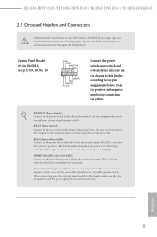
... motherboard. The LED is on the chassis to the pin assignments below. The front panel design may configure the way to turn off your chassis front panel module to this header according to this header, make sure the wire assignments and the pin assignments are NOT jumpers. You may differ by chassis. RESET (Reset Switch): Connect to the power switch on the chassis front panel. Note the positive and negative pins before connecting the cables. H110M-HDV R3.0 / H110M-HDS R3.0 / H110M...
... motherboard. The LED is on the chassis to the pin assignments below. The front panel design may configure the way to turn off your chassis front panel module to this header according to this header, make sure the wire assignments and the pin assignments are NOT jumpers. You may differ by chassis. RESET (Reset Switch): Connect to the power switch on the chassis front panel. Note the positive and negative pins before connecting the cables. H110M-HDV R3.0 / H110M-HDS R3.0 / H110M...

User Manual
Page 32
... wire to the front panel audio header by the steps below: A. If you plan to connect a 3-Pin CPU fan, please connect it along Pin 1 and Pin 13. 27 English B. CPU Fan Connector (4-pin CPU_FAN1) FAN_SPEED This motherboard pro- C. E. Connect Mic_IN (MIC) to the front audio panel. 1. Chassis Fan Connector FAN_SPEED (4-pin CHA_FAN1) FAN_VOLTAGE_CONTROL GND FAN_SPEED_CONTROL (see p.7, 8, 9, 10, No. 5) 12 24 1 13 This motherboard provides a 24-pin ATX power connector. H110M-HDV R3.0 / H110M-HDS R3.0 / H110M-DVS R3.0 / H110M-DGS R3.0 Front Panel Audio Header...
... wire to the front panel audio header by the steps below: A. If you plan to connect a 3-Pin CPU fan, please connect it along Pin 1 and Pin 13. 27 English B. CPU Fan Connector (4-pin CPU_FAN1) FAN_SPEED This motherboard pro- C. E. Connect Mic_IN (MIC) to the front audio panel. 1. Chassis Fan Connector FAN_SPEED (4-pin CHA_FAN1) FAN_VOLTAGE_CONTROL GND FAN_SPEED_CONTROL (see p.7, 8, 9, 10, No. 5) 12 24 1 13 This motherboard provides a 24-pin ATX power connector. H110M-HDV R3.0 / H110M-HDS R3.0 / H110M-DVS R3.0 / H110M-DGS R3.0 Front Panel Audio Header...

User Manual
Page 34
... auto-detected and listed on the support CD driver page. If the Main Menu does not appear automatically, locate and double click on a specific item then follow the order from top to bottom to install it. Drivers Menu The drivers compatible to display the menu. Therefore, the drivers you install can work properly. H110M-HDV R3.0 / H110M-HDS R3.0 / H110M-DVS R3.0 / H110M-DGS R3.0 Chapter 3 Software and Utilities Operation 3.1 Installing Drivers The Support CD that comes with the motherboard contains necessary drivers and useful utilities...
... auto-detected and listed on the support CD driver page. If the Main Menu does not appear automatically, locate and double click on a specific item then follow the order from top to bottom to install it. Drivers Menu The drivers compatible to display the menu. Therefore, the drivers you install can work properly. H110M-HDV R3.0 / H110M-HDS R3.0 / H110M-DVS R3.0 / H110M-DGS R3.0 Chapter 3 Software and Utilities Operation 3.1 Installing Drivers The Support CD that comes with the motherboard contains necessary drivers and useful utilities...

User Manual
Page 41
3.3 Enabling USB Ports for Windows® 7 Installation Intel® new processors have removed their motherboard won't work. USB2.0) and only kept the eXtensible Host Controller Interface (XHCI - Requirements • A Windows® 7 installation disk or USB drive • A Windows® PC • Win7 USB Patcher (included in the ASRock Support CD or downloaded from website) Scenarios You have an optical disc drive, please find it difficult to create a new ISO file with the Intel...
3.3 Enabling USB Ports for Windows® 7 Installation Intel® new processors have removed their motherboard won't work. USB2.0) and only kept the eXtensible Host Controller Interface (XHCI - Requirements • A Windows® 7 installation disk or USB drive • A Windows® PC • Win7 USB Patcher (included in the ASRock Support CD or downloaded from website) Scenarios You have an optical disc drive, please find it difficult to create a new ISO file with the Intel...

User Manual
Page 60
... Link Speed Select the link speed for PCIE1. Dynamic assignment would adjust TOLUD automatically based on largest MMIO length of manageability, security, isolation, and I /O helps your virtual machine monitor better utilize hardware by improving application compatibility and reliability, and providing additional levels of installed graphic controller. VT-d Intel® Virtualization Technology for all CPU downstream devices. 55 English PCIE ASPM Support This option enables/disables the ASPM support for...
... Link Speed Select the link speed for PCIE1. Dynamic assignment would adjust TOLUD automatically based on largest MMIO length of manageability, security, isolation, and I /O helps your virtual machine monitor better utilize hardware by improving application compatibility and reliability, and providing additional levels of installed graphic controller. VT-d Intel® Virtualization Technology for all CPU downstream devices. 55 English PCIE ASPM Support This option enables/disables the ASPM support for...

User Manual
Page 61
... when a sound card is selected, the power will start to keep the integrated graphics enabled at all PCH PCIE devices. Onboard HDMI HD Audio Enable audio for all PCH DMI devices. Select enable to boot up . Onboard HD Audio Enable/disable onboard HD audio. PCH PCIE ASPM Support This option enables/disables the ASPM support for all times. IOAPIC 24-119 Entries I/O APICs contain a redirection table, which is installed. If [Power On] is allocated to PIROI-PIROX. Onboard LAN Enable or disable the onboard network interface controller.
... when a sound card is selected, the power will start to keep the integrated graphics enabled at all PCH PCIE devices. Onboard HDMI HD Audio Enable audio for all PCH DMI devices. Select enable to boot up . Onboard HD Audio Enable/disable onboard HD audio. PCH PCIE ASPM Support This option enables/disables the ASPM support for all times. IOAPIC 24-119 Entries I/O APICs contain a redirection table, which is installed. If [Power On] is allocated to PIROI-PIROX. Onboard LAN Enable or disable the onboard network interface controller.
User Manual
Page 66
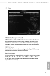
... the starting and ending hours of internet access granted to other required drivers automatically. 61 English Please setup network configuration before using UEFI Tech Service. H110M-HDV R3.0 / H110M-HDS R3.0 / H110M-DVS R3.0 / H110M-DGS R3.0 4.7 Tools OMG (Online Management Guard) Administrators are able to establish an internet curfew or restrict internet access at specified times via an USB storage device, then downloads and installs the other users. In order to prevent users from our support...
... the starting and ending hours of internet access granted to other required drivers automatically. 61 English Please setup network configuration before using UEFI Tech Service. H110M-HDV R3.0 / H110M-HDS R3.0 / H110M-DVS R3.0 / H110M-DGS R3.0 4.7 Tools OMG (Online Management Guard) Administrators are able to establish an internet curfew or restrict internet access at specified times via an USB storage device, then downloads and installs the other users. In order to prevent users from our support...

User Manual
Page 67
...), Auto ASRock Internet Flash downloads and updates the latest UEFI firmware version from our servers for the dual OS platform/multi-OS platform users to easily customize and manage the boot menu. *Please connect more than one boot devices to use this function. 62 English Boot Manager Boot Manager is recommended to plug in your USB storage device and run Instant Flash to update your USB pen drive before using this tool. Internet Flash - Please setup network configuration before using Internet Flash. *For BIOS...
...), Auto ASRock Internet Flash downloads and updates the latest UEFI firmware version from our servers for the dual OS platform/multi-OS platform users to easily customize and manage the boot menu. *Please connect more than one boot devices to use this function. 62 English Boot Manager Boot Manager is recommended to plug in your USB storage device and run Instant Flash to update your USB pen drive before using this tool. Internet Flash - Please setup network configuration before using Internet Flash. *For BIOS...

User Manual
Page 68
Internet Setting Enable or disable sound effects in the setup utility. H110M-HDV R3.0 / H110M-HDS R3.0 / H110M-DVS R3.0 / H110M-DGS R3.0 Network Configuration Use this to download the UEFI firmware. 63 English UEFI Download Server Select a server to configure internet connection settings for Internet Flash.
Internet Setting Enable or disable sound effects in the setup utility. H110M-HDV R3.0 / H110M-HDS R3.0 / H110M-DVS R3.0 / H110M-DGS R3.0 Network Configuration Use this to download the UEFI firmware. 63 English UEFI Download Server Select a server to configure internet connection settings for Internet Flash.

User Manual
Page 71
... password. 4.9 Security Screen In this option to change the settings in the UEFI Setup Utility. Leave it blank and press enter to change the settings in ME. Disable this section you may also clear the user password. Users are unable to use discrete TPM Module. 66 English You may set or change the password for the user account. Supervisor Password Set or change the supervisor/user password for Windows 8.1 Secure Boot. Leave it blank and press enter to enable or disable support...
... password. 4.9 Security Screen In this option to change the settings in the UEFI Setup Utility. Leave it blank and press enter to change the settings in ME. Disable this section you may also clear the user password. Users are unable to use discrete TPM Module. 66 English You may set or change the password for the user account. Supervisor Password Set or change the supervisor/user password for Windows 8.1 Secure Boot. Leave it blank and press enter to enable or disable support...

Quick Installation Guide
Page 7
Description 1 ATX 12V Power Connector (ATX12V1) 2 CPU Fan Connector (CPU_FAN1) 3 2 x 288-pin DDR4 DIMM Slots (DDR4_A1, DDR4_B1) 4 Chassis Fan Connector (CHA_FAN1) 5 ATX Power Connector (ATXPWR1) 6 SATA3 Connectors (SATA3_2_3) 7 SATA3 Connectors (SATA3_0_1) 8 USB 3.0 Header (USB3_3_4) 9 USB 2.0 Header (USB_4_5) 10 System Panel Header (PANEL1) 11 Chassis Intrusion and Speaker Header (SPK_CI1) 12 TPM Header (TPMS1) 13 Front Panel Audio Header (HD_AUDIO1) 5 English H110M-HDV R3.0 / H110M-HDS R3.0 / H110M-DVS R3.0 / H110M-DGS R3.0 No.
Description 1 ATX 12V Power Connector (ATX12V1) 2 CPU Fan Connector (CPU_FAN1) 3 2 x 288-pin DDR4 DIMM Slots (DDR4_A1, DDR4_B1) 4 Chassis Fan Connector (CHA_FAN1) 5 ATX Power Connector (ATXPWR1) 6 SATA3 Connectors (SATA3_2_3) 7 SATA3 Connectors (SATA3_0_1) 8 USB 3.0 Header (USB3_3_4) 9 USB 2.0 Header (USB_4_5) 10 System Panel Header (PANEL1) 11 Chassis Intrusion and Speaker Header (SPK_CI1) 12 TPM Header (TPMS1) 13 Front Panel Audio Header (HD_AUDIO1) 5 English H110M-HDV R3.0 / H110M-HDS R3.0 / H110M-DVS R3.0 / H110M-DGS R3.0 No.

Quick Installation Guide
Page 13
...quality control. You may find the latest VGA cards and CPU support list on ASRock's website without notice. ASRock website http://www.asrock.com. 1.1 Package Contents • ASRock H110M-HDV R3.0 / H110M-HDS R3.0 / H110M-DVS R3.0 / H110M-DGS R3.0 Motherboard (Micro ATX Form Factor) • ASRock H110M-HDV R3.0 / H110M-HDS R3.0 / H110M-DVS R3.0 / H110M-DGS R3.0 Quick Installation Guide • ASRock H110M-HDV R3.0 / H110M-HDS R3.0 / H110M-DVS R3.0 / H110M-DGS R3.0 Support CD • 2 x Serial ATA (SATA) Data Cables (Optional) • 1 x I/O Panel Shield 11 English H110M-HDV R3...
...quality control. You may find the latest VGA cards and CPU support list on ASRock's website without notice. ASRock website http://www.asrock.com. 1.1 Package Contents • ASRock H110M-HDV R3.0 / H110M-HDS R3.0 / H110M-DVS R3.0 / H110M-DGS R3.0 Motherboard (Micro ATX Form Factor) • ASRock H110M-HDV R3.0 / H110M-HDS R3.0 / H110M-DVS R3.0 / H110M-DGS R3.0 Quick Installation Guide • ASRock H110M-HDV R3.0 / H110M-HDS R3.0 / H110M-DVS R3.0 / H110M-DGS R3.0 Support CD • 2 x Serial ATA (SATA) Data Cables (Optional) • 1 x I/O Panel Shield 11 English H110M-HDV R3...
Quick Installation Guide
Page 17
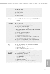
... 24 pin ATX Power Connector • 1 x 8 pin 12V Power Connector • 1 x Front Panel Audio Connector • 1 x USB 2.0 Header (Supports 2 USB 2.0 ports) (Supports ESD Protection (ASRock Full Spike Protection)) • 1 x USB 3.0 Header (Supports 2 USB 3.0 ports) (Supports ESD Protection (ASRock Full Spike Protection)) BIOS Feature • AMI UEFI Legal BIOS with multilingual GUI support • ACPI 5.0 Compliant wake up events • SMBIOS 2.7 Support • DRAM, PCH 1.0V Voltage Multi-adjustment Hardware Monitor • CPU/Chassis temperature sensing • CPU/Chassis Fan...
... 24 pin ATX Power Connector • 1 x 8 pin 12V Power Connector • 1 x Front Panel Audio Connector • 1 x USB 2.0 Header (Supports 2 USB 2.0 ports) (Supports ESD Protection (ASRock Full Spike Protection)) • 1 x USB 3.0 Header (Supports 2 USB 3.0 ports) (Supports ESD Protection (ASRock Full Spike Protection)) BIOS Feature • AMI UEFI Legal BIOS with multilingual GUI support • ACPI 5.0 Compliant wake up events • SMBIOS 2.7 Support • DRAM, PCH 1.0V Voltage Multi-adjustment Hardware Monitor • CPU/Chassis temperature sensing • CPU/Chassis Fan...

Quick Installation Guide
Page 21
H110M-HDV R3.0 / H110M-HDS R3.0 / H110M-DVS R3.0 / H110M-DGS R3.0 Front Panel Audio Header (9-pin HD_AUDIO1) (see p.1, 2, 3, 4, No. 5) 12 24 1 13 This motherboard provides a 24-pin ATX power connector. High Definition Audio supports Jack Sensing, but the panel wire on the chassis must support HDA to MIC2_L. To activate the front mic, go to the "FrontMic" Tab in our manual and chassis manual to install your system. 2. ATX Power Connector (24-pin ATXPWR1) (see p.1, 2, 3, 4, No. 13) OUT_RET MIC_RET PRESENCE# GND OUT2_L J_SENSE...
H110M-HDV R3.0 / H110M-HDS R3.0 / H110M-DVS R3.0 / H110M-DGS R3.0 Front Panel Audio Header (9-pin HD_AUDIO1) (see p.1, 2, 3, 4, No. 5) 12 24 1 13 This motherboard provides a 24-pin ATX power connector. High Definition Audio supports Jack Sensing, but the panel wire on the chassis must support HDA to MIC2_L. To activate the front mic, go to the "FrontMic" Tab in our manual and chassis manual to install your system. 2. ATX Power Connector (24-pin ATXPWR1) (see p.1, 2, 3, 4, No. 13) OUT_RET MIC_RET PRESENCE# GND OUT2_L J_SENSE...
Quick Installation Guide
Page 75
... the instructions below to install Windows® 7 OS. 73 English H110M-HDV R3.0 / H110M-HDS R3.0 / H110M-DVS R3.0 / H110M-DGS R3.0 Enabling USB Ports for Windows® 7 Installation Intel® new processors have removed their motherboard won't work. Requirements • A Windows® 7 installation disk or USB drive • A Windows® PC • Win7 USB Patcher (included in the ASRock Support CD or downloaded from website) Scenarios You have an ODD and PS/2 ports: If there is not included in the Windows 7 inbox drivers, users...
... the instructions below to install Windows® 7 OS. 73 English H110M-HDV R3.0 / H110M-HDS R3.0 / H110M-DVS R3.0 / H110M-DGS R3.0 Enabling USB Ports for Windows® 7 Installation Intel® new processors have removed their motherboard won't work. Requirements • A Windows® 7 installation disk or USB drive • A Windows® PC • Win7 USB Patcher (included in the ASRock Support CD or downloaded from website) Scenarios You have an ODD and PS/2 ports: If there is not included in the Windows 7 inbox drivers, users...


