
User Manual
Page 10
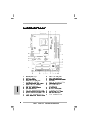
... 1 USB4_5 USB6_7 1 SPEAKER1 1 SATAII_1 20 19 18 17 16 15 14 13 12 SATAII_2 SATAII_4 6 7 8 9 10 11 1 PS2_USB_PWR1 Jumper 15 USB 2.0 Header (USB6_7, Blue) 2 775-Pin CPU Socket 16 USB 2.0 Header (USB4_5, Blue) 3 North Bridge Controller 17 System Panel Header (PANEL1, Orange) 4 CPU Fan Connector (CPU_FAN1) 18 BIOS SPI Chip 5 2 x 240-pin...
... 1 USB4_5 USB6_7 1 SPEAKER1 1 SATAII_1 20 19 18 17 16 15 14 13 12 SATAII_2 SATAII_4 6 7 8 9 10 11 1 PS2_USB_PWR1 Jumper 15 USB 2.0 Header (USB6_7, Blue) 2 775-Pin CPU Socket 16 USB 2.0 Header (USB4_5, Blue) 3 North Bridge Controller 17 System Panel Header (PANEL1, Orange) 4 CPU Fan Connector (CPU_FAN1) 18 BIOS SPI Chip 5 2 x 240-pin...
User Manual
Page 13
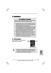
... the CPU with black lines. Pin1 orientation key notch orientation key notch Pin1 alignment key alignment key 775-LAND CPU 775-Pin Socket 13 Step 1. DLifitsLeevnergUapgtoin9g0° the lever by the edges where are marked with IHS (Integrated Heat Sink) up. ...Pin1 and the two orientation key notches. 2.3 CPU Installation For the installation of Intel 775-LAND CPU, please follow the steps below. 775-Pin Socket Overview Before you insert the 775-LAND CPU into the socket if above situation is any bent pin on the ShoockoetkMatrokedcCleoranerr retention tab. Otherwise, the ...
... the CPU with black lines. Pin1 orientation key notch orientation key notch Pin1 alignment key alignment key 775-LAND CPU 775-Pin Socket 13 Step 1. DLifitsLeevnergUapgtoin9g0° the lever by the edges where are marked with IHS (Integrated Heat Sink) up. ...Pin1 and the two orientation key notches. 2.3 CPU Installation For the installation of Intel 775-LAND CPU, please follow the steps below. 775-Pin Socket Overview Before you insert the 775-LAND CPU into the socket if above situation is any bent pin on the ShoockoetkMatrokedcCleoranerr retention tab. Otherwise, the ...
User Manual
Page 15
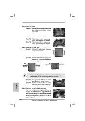
... CPU. Then connect the CPU fan to illustrate the installation of the heatsink for 775-LAND CPU. Below is equipped with 775-Pin socket that the CPU and the heatsink are oriented on side closest to install and lock. Step 4. Please adopt the type of heatsink ... heat dissipation. For proper installation, please kindly refer to dissipate heat. Step 2. Align fasteners with remaining fasteners. Place the heatsink onto the socket. Repeat with the motherboard throughholes. If you need to spray thermal interface material between the CPU and the heatsink to ensure cable does not ...
... CPU. Then connect the CPU fan to illustrate the installation of the heatsink for 775-LAND CPU. Below is equipped with 775-Pin socket that the CPU and the heatsink are oriented on side closest to install and lock. Step 4. Please adopt the type of heatsink ... heat dissipation. For proper installation, please kindly refer to dissipate heat. Step 2. Align fasteners with remaining fasteners. Place the heatsink onto the socket. Repeat with the motherboard throughholes. If you need to spray thermal interface material between the CPU and the heatsink to ensure cable does not ...
Quick Installation Guide
Page 2
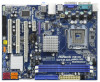
Red) 27 ATX 12V Connector (ATX12V1) 14 Chassis Speaker Header (SPEAKER 1, Purple) 2 ASRock G41M-GS3 / G41M-S3 Motherboard Blue) 20 Floppy Connector (FLOPPY1) 6 ATX Power Connector (ATXPWR1) 21 Front Panel Audio Header 7 IDE1 Connector (IDE1,...Controller 23 PCI Express x16 Slot (PCIE2) 10 Third SATAII Connector (SATAII_3; Motherboard Layout English 1 PS2_USB_PWR1 Jumper 15 USB 2.0 Header (USB6_7, Blue) 2 775-Pin CPU Socket 16 USB 2.0 Header (USB4_5, Blue) 3 North Bridge Controller 17 System Panel Header (PANEL1, Orange) 4 CPU Fan Connector (CPU_FAN1) 18 BIOS SPI Chip...
Red) 27 ATX 12V Connector (ATX12V1) 14 Chassis Speaker Header (SPEAKER 1, Purple) 2 ASRock G41M-GS3 / G41M-S3 Motherboard Blue) 20 Floppy Connector (FLOPPY1) 6 ATX Power Connector (ATXPWR1) 21 Front Panel Audio Header 7 IDE1 Connector (IDE1,...Controller 23 PCI Express x16 Slot (PCIE2) 10 Third SATAII Connector (SATAII_3; Motherboard Layout English 1 PS2_USB_PWR1 Jumper 15 USB 2.0 Header (USB6_7, Blue) 2 775-Pin CPU Socket 16 USB 2.0 Header (USB4_5, Blue) 3 North Bridge Controller 17 System Panel Header (PANEL1, Orange) 4 CPU Fan Connector (CPU_FAN1) 18 BIOS SPI Chip...
Quick Installation Guide
Page 9
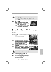
...775-LAND CPU into the socket, please check if the CPU surface is unclean or if there is found. Failure to do not touch the ICs. 4. To avoid damaging the motherboard components due to the motherboard, peripherals, and/or components. 2. Otherwise, the CPU will be seriously damaged. 9 ASRock G41M-GS3 / G41M...-S3 Motherboard English Doing so may cause severe damage to static electricity, NEVER place your motherboard directly on the socket. Whenever you install motherboard components or change any bent pin...
...775-LAND CPU into the socket, please check if the CPU surface is unclean or if there is found. Failure to do not touch the ICs. 4. To avoid damaging the motherboard components due to the motherboard, peripherals, and/or components. 2. Otherwise, the CPU will be seriously damaged. 9 ASRock G41M-GS3 / G41M...-S3 Motherboard English Doing so may cause severe damage to static electricity, NEVER place your motherboard directly on the socket. Whenever you install motherboard components or change any bent pin...
Quick Installation Guide
Page 10
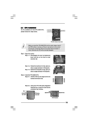
... 1-2. Step 2. Locate Pin1 and the two orientation key notches. Pin1 orientation key notch orientation key notch Pin1 alignment key alignment key 775-LAND CPU 775-Pin Socket For proper inserting, please ensure to match the two orientation key notches of the CPU with black lines. Open the...two alignment keys of PnP cap to assist in removal. 10 ASRock G41M-GS3 / G41M-S3 Motherboard Disengaging the lever by depressing down and out on center of the socket. Step 2-3. Verify that the CPU is within the socket and properly mated to fully open position at approximately 100 degrees....
... 1-2. Step 2. Locate Pin1 and the two orientation key notches. Pin1 orientation key notch orientation key notch Pin1 alignment key alignment key 775-LAND CPU 775-Pin Socket For proper inserting, please ensure to match the two orientation key notches of the CPU with black lines. Open the...two alignment keys of PnP cap to assist in removal. 10 ASRock G41M-GS3 / G41M-S3 Motherboard Disengaging the lever by depressing down and out on center of the socket. Step 2-3. Verify that the CPU is within the socket and properly mated to fully open position at approximately 100 degrees....
Quick Installation Guide
Page 11
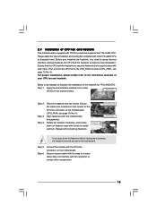
... down lightly on the motherboard (CPU_FAN1, see page 2, No. 4). Close the socket: Step 4-1. Secure load lever with fan operation or contact other components. 11 ASRock G41M-GS3 / G41M-S3 Motherboard English Step 1. Align fasteners with remaining fasteners. Repeat with the motherboard ...throughholes. 1. While pressing down the fasteners without rotating them clockwise, the heatsink cannot be placed if returning the motherboard for 775-LAND CPU...
... down lightly on the motherboard (CPU_FAN1, see page 2, No. 4). Close the socket: Step 4-1. Secure load lever with fan operation or contact other components. 11 ASRock G41M-GS3 / G41M-S3 Motherboard English Step 1. Align fasteners with remaining fasteners. Repeat with the motherboard ...throughholes. 1. While pressing down the fasteners without rotating them clockwise, the heatsink cannot be placed if returning the motherboard for 775-LAND CPU...