
User Manual
Page 5
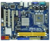
...ASRock G41M-GS motherboard, a reliable motherboard produced under ASRock's consistently stringent quality control. In this manual, chapter 1 and 2 contain introduction of the Support CD. www.asrock.com/support/index.asp 1.1 Package Contents ASRock G41M-GS Motherboard (Micro ATX Form Factor: 9.6-in x 7.6-in, 24.4 cm x 19.3 cm) ASRock G41M-GS Quick Installation Guide ASRock G41M-GS Support... guide to the hardware installation. You may find the latest VGA cards and CPU support lists on ASRock website without notice. Because the motherboard specifications and the BIOS software might be ...
...ASRock G41M-GS motherboard, a reliable motherboard produced under ASRock's consistently stringent quality control. In this manual, chapter 1 and 2 contain introduction of the Support CD. www.asrock.com/support/index.asp 1.1 Package Contents ASRock G41M-GS Motherboard (Micro ATX Form Factor: 9.6-in x 7.6-in, 24.4 cm x 19.3 cm) ASRock G41M-GS Quick Installation Guide ASRock G41M-GS Support... guide to the hardware installation. You may find the latest VGA cards and CPU support lists on ASRock website without notice. Because the motherboard specifications and the BIOS software might be ...
User Manual
Page 6
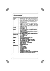
... MHz (see CAUTION 7) - 5.1 CH Windows® VistaTM Premium Level HD Audio (Realtek ALC662 Audio Codec) - Northbridge: Intel® G41 - shared memory 352MB (see CAUTION 1) - Supports EM64T CPU - Southbridge: Intel® ICH7 - capacity of system memory: 8GB (see CAUTION 3) - Intel® Graphics Media Accelerator X4500 - Realtek RTL8111DL - HD Audio Jack: Line in , 24...
... MHz (see CAUTION 7) - 5.1 CH Windows® VistaTM Premium Level HD Audio (Realtek ALC662 Audio Codec) - Northbridge: Intel® G41 - shared memory 352MB (see CAUTION 1) - Supports EM64T CPU - Southbridge: Intel® ICH7 - capacity of system memory: 8GB (see CAUTION 3) - Intel® Graphics Media Accelerator X4500 - Realtek RTL8111DL - HD Audio Jack: Line in , 24...

User Manual
Page 7
... power connector - ACPI 1.1 Compliance Wake Up Events - Supports Smart BIOS Support CD - ASRock U-COP (see CAUTION 13) - CPU Fan Tachometer - Voltage Monitoring: +12V, +5V, +3.3V, Vcore OS - AMI Legal BIOS - CPU Frequency Stepless Control (see CAUTION 14) - Chassis Temperature Sensing - CPU Quiet Fan - Connector - 4 x SATAII 3.0 Gb/s connectors (No Support for RAID and "Hot Plug" functions) (see CAUTION...
... power connector - ACPI 1.1 Compliance Wake Up Events - Supports Smart BIOS Support CD - ASRock U-COP (see CAUTION 13) - CPU Fan Tachometer - Voltage Monitoring: +12V, +5V, +3.3V, Vcore OS - AMI Legal BIOS - CPU Frequency Stepless Control (see CAUTION 14) - Chassis Temperature Sensing - CPU Quiet Fan - Connector - 4 x SATAII 3.0 Gb/s connectors (No Support for RAID and "Hot Plug" functions) (see CAUTION...
User Manual
Page 8
...usage under Microsoft® Windows® VistaTM 64-bit / VistaTM / XP 64-bit / XP SP1 or SP2 / 2000 SP4. 10. ASRock website: http://www.asrock.com 8 It should be less than 4GB for the reservation for the operation procedures of memory modules on page 24 to change. This motherboard... please check page 31. 3. It is subject to adjust your own risk and expense. We are not responsible for the CPU FSB frequency and its corresponding memory support frequency. Due to the operating system limitation, the actual memory size may affect your system stability, or even cause damage to...
...usage under Microsoft® Windows® VistaTM 64-bit / VistaTM / XP 64-bit / XP SP1 or SP2 / 2000 SP4. 10. ASRock website: http://www.asrock.com 8 It should be less than 4GB for the reservation for the operation procedures of memory modules on page 24 to change. This motherboard... please check page 31. 3. It is subject to adjust your own risk and expense. We are not responsible for the CPU FSB frequency and its corresponding memory support frequency. Due to the operating system limitation, the actual memory size may affect your system stability, or even cause damage to...
User Manual
Page 14
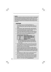
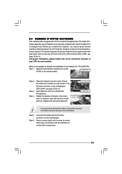
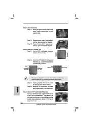
Verify that the CPU is recommended to use the cap tab to the orient keys. Step 3. Rotate the load plate onto the IHS. Remove PnP Cap (Pick and Place Cap): Use your left hand index finger and thumb to support the load plate edge, engage PnP cap with right hand thumb and peel... cap to assist in removal. 1. For proper inserting, please ensure to match the two orientation key notches of the CPU with the two alignment keys of load lever. 14 Carefully place the CPU into the socket by using a purely vertical motion. It is within the socket and properly mated to handle and...
Verify that the CPU is recommended to use the cap tab to the orient keys. Step 3. Rotate the load plate onto the IHS. Remove PnP Cap (Pick and Place Cap): Use your left hand index finger and thumb to support the load plate edge, engage PnP cap with right hand thumb and peel... cap to assist in removal. 1. For proper inserting, please ensure to match the two orientation key notches of the CPU with the two alignment keys of load lever. 14 Carefully place the CPU into the socket by using a purely vertical motion. It is within the socket and properly mated to handle and...
User Manual
Page 15
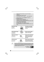
...ensure cable does not interfere with Intel 775-LAND CPU to dissipate heat. Step 2. Place the heatsink onto the socket. Ensure that supports Intel 775-LAND CPU. Step 1. Step 6. Connect fan header with remaining fasteners. Then connect the CPU fan to the CPU_FAN connector (CPU_FAN1, see ... fastened and in good contact with the motherboard throughholes. Step 5. Align fasteners with each other components. 15 2.4 Installation of CPU Fan and Heatsink This motherboard is an example to illustrate the installation of IHS on the socket surface. Step 4. If you...
...ensure cable does not interfere with Intel 775-LAND CPU to dissipate heat. Step 2. Place the heatsink onto the socket. Ensure that supports Intel 775-LAND CPU. Step 1. Step 6. Connect fan header with remaining fasteners. Then connect the CPU fan to the CPU_FAN connector (CPU_FAN1, see ... fastened and in good contact with the motherboard throughholes. Step 5. Align fasteners with each other components. 15 2.4 Installation of CPU Fan and Heatsink This motherboard is an example to illustrate the installation of IHS on the socket surface. Step 4. If you...
User Manual
Page 22
... (see p.10 No. 14) Chassis Fan Connector (3-pin CHA_FAN1) (see p.10 No. 4) 4 3 2 1 GND +12V CPU_FAN_SPEED FAN_SPEED_CONTROL Please connect a CPU fan cable to this motherboard, please connect it to the ground pin. For Windows® VistaTM / VistaTM 64-bit OS: Click the right-top "Folder...Connected 3-Pin Fan Installation 22 G. GND +12V CHA_FAN_SPEED Please connect a chassis fan cable to this motherboard provides 4-Pin CPU fan (Quiet Fan) support, the 3-Pin CPU fan still can work successfully even without the fan speed control function. Click "Set Default Device" to make the Front...
... (see p.10 No. 14) Chassis Fan Connector (3-pin CHA_FAN1) (see p.10 No. 4) 4 3 2 1 GND +12V CPU_FAN_SPEED FAN_SPEED_CONTROL Please connect a CPU fan cable to this motherboard, please connect it to the ground pin. For Windows® VistaTM / VistaTM 64-bit OS: Click the right-top "Folder...Connected 3-Pin Fan Installation 22 G. GND +12V CHA_FAN_SPEED Please connect a chassis fan cable to this motherboard provides 4-Pin CPU fan (Quiet Fan) support, the 3-Pin CPU fan still can work successfully even without the fan speed control function. Click "Set Default Device" to make the Front...
User Manual
Page 25
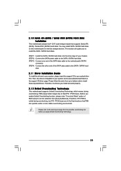
...the SATA data cable to the SATA / SATAII hard disk. 2.11 Driver Installation Guide To install the drivers to your system, please insert the support CD to the SATA / SATAII hard disk. Then, the drivers compatible to your chassis. Please follow the order from [Auto] to install ... to fixed PCI / PCIE buses. Therefore, the drivers you apply Untied Overclocking Technology. 25 Please refer to install those required drivers. Therefore, CPU FSB is untied during overclocking, FSB enjoys better margin due to the motherboard's SATAII connector. STEP 3: Connect one end of BIOS setup to...
...the SATA data cable to the SATA / SATAII hard disk. 2.11 Driver Installation Guide To install the drivers to your system, please insert the support CD to the SATA / SATAII hard disk. Then, the drivers compatible to your chassis. Please follow the order from [Auto] to install ... to fixed PCI / PCIE buses. Therefore, the drivers you apply Untied Overclocking Technology. 25 Please refer to install those required drivers. Therefore, CPU FSB is untied during overclocking, FSB enjoys better margin due to the motherboard's SATAII connector. STEP 3: Connect one end of BIOS setup to...
User Manual
Page 30
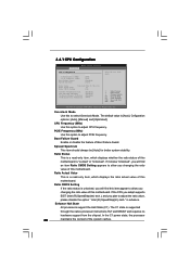
...14] Intel (R) Virtualization tech. The default value is unlocked, you will find this to adjust CPU frequency. Cnfiguration options: [Auto], [Manual] and [Optimized]. If the CPU you adopt supports EIST (Intel (R) SpeedStep(tm) tech.), and you changing the ratio value of this motherboard. ...to adjust the ratio value, please disable the option " Intel (R) SpeedStep(tm) tech." Enhance Halt State All processors support the Halt State (C1). CPU Thermal Throttling No-Excute Memory Protection On-Demand Clock Modulation [Enabled] [Enabled] [Disabled] [Auto] Select the over ...
...14] Intel (R) Virtualization tech. The default value is unlocked, you will find this to adjust CPU frequency. Cnfiguration options: [Auto], [Manual] and [Optimized]. If the CPU you adopt supports EIST (Intel (R) SpeedStep(tm) tech.), and you changing the ratio value of this motherboard. ...to adjust the ratio value, please disable the option " Intel (R) SpeedStep(tm) tech." Enhance Halt State All processors support the Halt State (C1). CPU Thermal Throttling No-Excute Memory Protection On-Demand Clock Modulation [Enabled] [Enabled] [Disabled] [Auto] Select the over ...
User Manual
Page 31
...; Windows® XP. The default value is set this item to [75.0% On], your processor will be hidden if the current CPU does not support Intel (R) SpeedStep(tm) tech.. This option will work normally 75% of the time, and spend the other 25% slacking off interval...-Threading technology. Intel (R) Virtualization tech. Processor can prevent data pages from overheated. This option will be hidden if the current CPU does not support CPU Thermal Throttling. Configuration options: [Auto], [Disabled], [12.5% On], [25.0% On], [37.5% On], [50.0% On], [62.5% On], [75.0% On] and [...
...; Windows® XP. The default value is set this item to [75.0% On], your processor will be hidden if the current CPU does not support Intel (R) SpeedStep(tm) tech.. This option will work normally 75% of the time, and spend the other 25% slacking off interval...-Threading technology. Intel (R) Virtualization tech. Processor can prevent data pages from overheated. This option will be hidden if the current CPU does not support CPU Thermal Throttling. Configuration options: [Auto], [Disabled], [12.5% On], [25.0% On], [37.5% On], [50.0% On], [62.5% On], [75.0% On] and [...
User Manual
Page 32
... number of overlapped PCI memory above the total physical memory. The configuration options depend on the CPU and memory module you adopt on this item to page 8 for the CPU FSB frequency and its corresponding memory support frequency. Min: 3. Max: 7. The default value is [Auto]. Max: 10. Max: 24. 3.4.2 Chipset Configuration BIOS SETUP...
... number of overlapped PCI memory above the total physical memory. The configuration options depend on the CPU and memory module you adopt on this item to page 8 for the CPU FSB frequency and its corresponding memory support frequency. Min: 3. Max: 7. The default value is [Auto]. Max: 10. Max: 24. 3.4.2 Chipset Configuration BIOS SETUP...
User Manual
Page 38
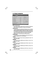
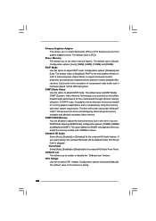
... detect physical memory available and allocate necessary video memory. The option [Maximum DVMT] only appears when you to select CPU Voltage. In DVMT mode, the graphics driver allocates memory as needed for premium content playback (Bluray disc). [Lite]...adapter priority. Configuration options: [128MB], [256MB] and [Maximum DVMT]. Configuration options: [Auto] and [Manual]. CPU Voltage Use this option to support increased content protection and robustness requirements for running graphics applications and is cooperatively using this feature is plugged. PAVP is...
... detect physical memory available and allocate necessary video memory. The option [Maximum DVMT] only appears when you to select CPU Voltage. In DVMT mode, the graphics driver allocates memory as needed for premium content playback (Bluray disc). [Lite]...adapter priority. Configuration options: [128MB], [256MB] and [Maximum DVMT]. Configuration options: [Auto] and [Manual]. CPU Voltage Use this option to support increased content protection and robustness requirements for running graphics applications and is cooperatively using this feature is plugged. PAVP is...

Quick Installation Guide
Page 4
... as well. You may find the latest VGA cards and CPU support lists on ASRock website without notice. This Quick Installation Guide contains introduction of this motherboard, please visit our website for purchasing ASRock G41M-GS motherboard, a reliable motherboard produced under ASRock's consistently stringent quality control. Introduction Thank you for specific information about the model you require...
... as well. You may find the latest VGA cards and CPU support lists on ASRock website without notice. This Quick Installation Guide contains introduction of this motherboard, please visit our website for purchasing ASRock G41M-GS motherboard, a reliable motherboard produced under ASRock's consistently stringent quality control. Introduction Thank you for specific information about the model you require...
Quick Installation Guide
Page 5
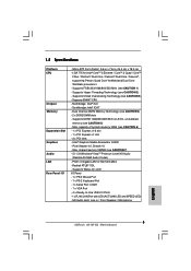
... ALC662 Audio Codec) - Max. Realtek RTL8111DL - HD Audio Jack: Line in , 24.4 cm x 19.3 cm - Supports EM64T CPU - Intel® Graphics Media Accelerator X4500 - Supports Wake-On-LAN I /O - Micro ATX Form Factor: 9.6-in x 7.6-in / Front Speaker / Microphone English 5 ASRock G41M-GS Motherboard Dual Channel DDR2 Memory Technology (see CAUTION 1) - PCIE x1 Gigabit LAN 10/100/1000...
... ALC662 Audio Codec) - Max. Realtek RTL8111DL - HD Audio Jack: Line in , 24.4 cm x 19.3 cm - Supports EM64T CPU - Intel® Graphics Media Accelerator X4500 - Supports Wake-On-LAN I /O - Micro ATX Form Factor: 9.6-in x 7.6-in / Front Speaker / Microphone English 5 ASRock G41M-GS Motherboard Dual Channel DDR2 Memory Technology (see CAUTION 1) - PCIE x1 Gigabit LAN 10/100/1000...

Quick Installation Guide
Page 6
... Legal BIOS - CPU Frequency Stepless Control (see CAUTION 14) - ASRock U-COP (see CAUTION 13) - ACPI 1.1 Compliance Wake Up Events - ASRock Instant Flash (see CAUTION 15) * For detailed product information, please visit our website: http://www.asrock.com English 6 ASRock G41M-GS Motherboard Chassis Fan Tachometer - Voltage Monitoring: +12V, +5V, +3.3V, Vcore OS - Supports Smart BIOS Support CD - Microsoft®...
... Legal BIOS - CPU Frequency Stepless Control (see CAUTION 14) - ASRock U-COP (see CAUTION 13) - ACPI 1.1 Compliance Wake Up Events - ASRock Instant Flash (see CAUTION 15) * For detailed product information, please visit our website: http://www.asrock.com English 6 ASRock G41M-GS Motherboard Chassis Fan Tachometer - Voltage Monitoring: +12V, +5V, +3.3V, Vcore OS - Supports Smart BIOS Support CD - Microsoft®...

Quick Installation Guide
Page 7
... "SATAII Hard Disk Setup Guide" on page 24 of "User Manual" in the support CD to adjust your system. This motherboard supports Untied Overclocking Technology. English 7 ASRock G41M-GS Motherboard WARNING Please realize that there is a certain risk involved with 64-bit CPU, there is no such limitation. 7. It should be less than 4GB for the...
... "SATAII Hard Disk Setup Guide" on page 24 of "User Manual" in the support CD to adjust your system. This motherboard supports Untied Overclocking Technology. English 7 ASRock G41M-GS Motherboard WARNING Please realize that there is a certain risk involved with 64-bit CPU, there is no such limitation. 7. It should be less than 4GB for the...
Quick Installation Guide
Page 10
...to assist in removal. 10 ASRock G41M-GS Motherboard Hold the CPU by depressing down and out on center of the socket. Step 2-3. Step 1-2. Step 3. Step 1. Insert the 775-LAND CPU: Step 2-1. Remove PnP Cap (Pick and Place Cap): Use your left hand index finger and thumb to support the load plate edge, ...engage PnP cap with the two alignment keys of PnP cap to fully open position at approximately 135 degrees. Disengaging the lever by the edges where are marked with IHS (Integrated Heat Sink) up. Verify that the CPU is within the...
...to assist in removal. 10 ASRock G41M-GS Motherboard Hold the CPU by depressing down and out on center of the socket. Step 2-3. Step 1-2. Step 3. Step 1. Insert the 775-LAND CPU: Step 2-1. Remove PnP Cap (Pick and Place Cap): Use your left hand index finger and thumb to support the load plate edge, ...engage PnP cap with the two alignment keys of PnP cap to fully open position at approximately 135 degrees. Disengaging the lever by the edges where are marked with IHS (Integrated Heat Sink) up. Verify that the CPU is within the...

Quick Installation Guide
Page 18
.../ VistaTM 64-bit OS: Go to the "Front Mic" Tab in "Front Mic" of "Playback" portion. Pin 1-3 Connected 3-Pin Fan Installation English 18 ASRock G41M-GS Motherboard System Panel Header (9-pin PANEL1) (see p.2 No. 4) 4 3 2 1 Please connect the chassis speaker to hear your voice through front mic, please ...and save the change by clicking "OK". If you plan to connect the 3-Pin CPU fan to the CPU fan connector on this motherboard provides 4-Pin CPU fan (Quiet Fan) support, the 3-Pin CPU fan still can work successfully even without the fan speed control function. Click "Set ...
.../ VistaTM 64-bit OS: Go to the "Front Mic" Tab in "Front Mic" of "Playback" portion. Pin 1-3 Connected 3-Pin Fan Installation English 18 ASRock G41M-GS Motherboard System Panel Header (9-pin PANEL1) (see p.2 No. 4) 4 3 2 1 Please connect the chassis speaker to hear your voice through front mic, please ...and save the change by clicking "OK". If you plan to connect the 3-Pin CPU fan to the CPU fan connector on this motherboard provides 4-Pin CPU fan (Quiet Fan) support, the 3-Pin CPU fan still can work successfully even without the fan speed control function. Click "Set ...

Quick Installation Guide
Page 20
...to install the SATA / SATAII hard disks. Then, the drivers compatible to the SATA / SATAII hard disk. Therefore, CPU FSB is untied during overclocking, FSB enjoys better margin due to the warning on this motherboard for the possible overclocking risk ...optical drive first. This section will guide you apply Untied Overclocking Technology. 20 ASRock G41M-GS Motherboard English Therefore, the drivers you install can work properly. 2.9 Untied Overclocking Technology This motherboard supports Untied Overclocking Technology, which means during overclocking, but PCI / PCIE buses ...
...to install the SATA / SATAII hard disks. Then, the drivers compatible to the SATA / SATAII hard disk. Therefore, CPU FSB is untied during overclocking, FSB enjoys better margin due to the warning on this motherboard for the possible overclocking risk ...optical drive first. This section will guide you apply Untied Overclocking Technology. 20 ASRock G41M-GS Motherboard English Therefore, the drivers you install can work properly. 2.9 Untied Overclocking Technology This motherboard supports Untied Overclocking Technology, which means during overclocking, but PCI / PCIE buses ...


