
User Manual
Page 5
...the updated version will be available on ASRock website as well. www.asrock.com/support/index.asp 1.1 Package Contents ASRock G41M-GS Motherboard (Micro ATX Form Factor: 9.6-in x 7.6-in, 24.4 cm x 19.3 cm) ASRock G41M-GS Quick Installation Guide ASRock G41M-GS Support CD One 80-conductor Ultra ATA...notice. In this motherboard, please visit our website for specific information about the model you for purchasing ASRock G41M-GS motherboard, a reliable motherboard produced under ASRock's consistently stringent quality control. Chapter 3 and 4 contain the configuration guide to BIOS setup and ...
...the updated version will be available on ASRock website as well. www.asrock.com/support/index.asp 1.1 Package Contents ASRock G41M-GS Motherboard (Micro ATX Form Factor: 9.6-in x 7.6-in, 24.4 cm x 19.3 cm) ASRock G41M-GS Quick Installation Guide ASRock G41M-GS Support CD One 80-conductor Ultra ATA...notice. In this motherboard, please visit our website for specific information about the model you for purchasing ASRock G41M-GS motherboard, a reliable motherboard produced under ASRock's consistently stringent quality control. Chapter 3 and 4 contain the configuration guide to BIOS setup and ...

Quick Installation Guide
Page 1
... kind, either expressed or implied, including but not limited to the owners' benefit, without notice, and should not be constructed as a commitment by ASRock. All rights reserved. 1 ASRock G41M-GS Motherboard English When you discard the Lithium battery in California, USA, please follow the related regulations in this guide are used only for identification...
... kind, either expressed or implied, including but not limited to the owners' benefit, without notice, and should not be constructed as a commitment by ASRock. All rights reserved. 1 ASRock G41M-GS Motherboard English When you discard the Lithium battery in California, USA, please follow the related regulations in this guide are used only for identification...

Quick Installation Guide
Page 2
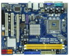
... SATAII Connector (SATAII_1; Red) 28 FSB1 / FSB2 / FSB3 Jumper 14 Chassis Speaker Header (SPEAKER 1, Purple) 29 ATX 12V Connector (ATX12V1) 15 USB 2.0 Header (USB6_7, Blue) 2 ASRock G41M-GS Motherboard Motherboard Layout English 1 PS2_USB_PWR1 Jumper 16 USB 2.0 Header (USB4_5, Blue) 2 775-Pin CPU Socket 17 System Panel Header (PANEL1, Orange) 3 North Bridge Controller 18...
... SATAII Connector (SATAII_1; Red) 28 FSB1 / FSB2 / FSB3 Jumper 14 Chassis Speaker Header (SPEAKER 1, Purple) 29 ATX 12V Connector (ATX12V1) 15 USB 2.0 Header (USB6_7, Blue) 2 ASRock G41M-GS Motherboard Motherboard Layout English 1 PS2_USB_PWR1 Jumper 16 USB 2.0 Header (USB4_5, Blue) 2 775-Pin CPU Socket 17 System Panel Header (PANEL1, Orange) 3 North Bridge Controller 18...

Quick Installation Guide
Page 3
..." tool on the system tray. Please select "Mixer ToolBox" , click "Enable playback multi-streaming", and click "ok". For Windows® VistaTM: After restarting your system. 3 ASRock G41M-GS Motherboard English Please refer to the table below steps for the LAN port LED indications. For Windows® XP: After restarting your system. I/O Panel 1 PS...
..." tool on the system tray. Please select "Mixer ToolBox" , click "Enable playback multi-streaming", and click "ok". For Windows® VistaTM: After restarting your system. 3 ASRock G41M-GS Motherboard English Please refer to the table below steps for the LAN port LED indications. For Windows® XP: After restarting your system. I/O Panel 1 PS...

Quick Installation Guide
Page 4
... installation guide. This Quick Installation Guide contains introduction of the motherboard can be found in the user manual presented in , 24.4 cm x 19.3 cm) ASRock G41M-GS Quick Installation Guide ASRock G41M-GS Support CD One 80-conductor Ultra ATA 66/100 IDE Ribbon Cable (Optional) One Serial ATA (SATA) Data Cable (Optional) One I/O Panel Shield...
... installation guide. This Quick Installation Guide contains introduction of the motherboard can be found in the user manual presented in , 24.4 cm x 19.3 cm) ASRock G41M-GS Quick Installation Guide ASRock G41M-GS Support CD One 80-conductor Ultra ATA 66/100 IDE Ribbon Cable (Optional) One Serial ATA (SATA) Data Cable (Optional) One I/O Panel Shield...
Quick Installation Guide
Page 5
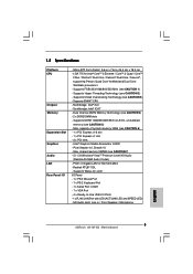
... FSB1333/1066/800/533 MHz (see CAUTION 5) - Intel® Graphics Media Accelerator X4500 - Realtek RTL8111DL - Micro ATX Form Factor: 9.6-in x 7.6-in / Front Speaker / Microphone English 5 ASRock G41M-GS Motherboard Supports DDR2 1066/800/667/533 non-ECC, un-buffered memory (see CAUTION 1) - Supports Hyper-Threading Technology (see CAUTION 6) - 1 x PCI Express x16 slot - 1 x PCI...
... FSB1333/1066/800/533 MHz (see CAUTION 5) - Intel® Graphics Media Accelerator X4500 - Realtek RTL8111DL - Micro ATX Form Factor: 9.6-in x 7.6-in / Front Speaker / Microphone English 5 ASRock G41M-GS Motherboard Supports DDR2 1066/800/667/533 non-ECC, un-buffered memory (see CAUTION 1) - Supports Hyper-Threading Technology (see CAUTION 6) - 1 x PCI Express x16 slot - 1 x PCI...

Quick Installation Guide
Page 6
... Tuner (see CAUTION 15) * For detailed product information, please visit our website: http://www.asrock.com English 6 ASRock G41M-GS Motherboard Boot Failure Guard (B.F.G.) Hardware - CPU Quiet Fan - FCC, CE - Drivers, Utilities, AntiVirus Software (Trial Version) Unique Feature - Instant Boot - CPU Temperature Sensing Monitor - CPU ...
... Tuner (see CAUTION 15) * For detailed product information, please visit our website: http://www.asrock.com English 6 ASRock G41M-GS Motherboard Boot Failure Guard (B.F.G.) Hardware - CPU Quiet Fan - FCC, CE - Drivers, Utilities, AntiVirus Software (Trial Version) Unique Feature - Instant Boot - CPU Temperature Sensing Monitor - CPU ...

Quick Installation Guide
Page 7
... Disk Setup Guide" on page 24 of "User Manual" in the support CD to adjust your SATAII hard disk drive to SATAII connector directly. 9. English 7 ASRock G41M-GS Motherboard CAUTION! 1. WARNING Please realize that there is a certain risk involved with 64-bit CPU, there is subject to change. For Windows® XP 64...
... Disk Setup Guide" on page 24 of "User Manual" in the support CD to adjust your SATAII hard disk drive to SATAII connector directly. 9. English 7 ASRock G41M-GS Motherboard CAUTION! 1. WARNING Please realize that there is a certain risk involved with 64-bit CPU, there is subject to change. For Windows® XP 64...
Quick Installation Guide
Page 8
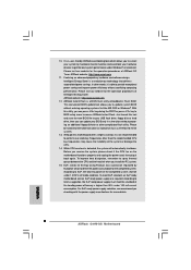
... for the operation procedures of Intelligent Energy Saver. Although this motherboard offers stepless control, it back again. 10. ASRock website: http://www.asrock.com 12. For EuP ready power supply selection, we recommend you to perform over-clocking. In other words, ... that delivers unparalleled power savings. It is detected, the system will automatically shutdown. Please visit our website for more details. 8 ASRock G41M-GS Motherboard English EuP, stands for Energy Using Product, was a provision regulated by hardware monitor function and overclock your BIOS only in...
... for the operation procedures of Intelligent Energy Saver. Although this motherboard offers stepless control, it back again. 10. ASRock website: http://www.asrock.com 12. For EuP ready power supply selection, we recommend you to perform over-clocking. In other words, ... that delivers unparalleled power savings. It is detected, the system will automatically shutdown. Please visit our website for more details. 8 ASRock G41M-GS Motherboard English EuP, stands for Energy Using Product, was a provision regulated by hardware monitor function and overclock your BIOS only in...

Quick Installation Guide
Page 9
... is any component, place it on a grounded antstatic pad or in the bag that comes with the component. 5. Otherwise, the CPU will be seriously damaged. 9 ASRock G41M-GS Motherboard English Unplug the power cord from the wall socket before you uninstall any bent pin on the carpet or the like. Also remember to...
... is any component, place it on a grounded antstatic pad or in the bag that comes with the component. 5. Otherwise, the CPU will be seriously damaged. 9 ASRock G41M-GS Motherboard English Unplug the power cord from the wall socket before you uninstall any bent pin on the carpet or the like. Also remember to...
Quick Installation Guide
Page 10
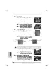
... plate edge, engage PnP cap with black lines. Step 2-4. Verify that the CPU is within the socket and properly mated to assist in removal. 10 ASRock G41M-GS Motherboard Step 3. Remove PnP Cap (Pick and Place Cap): Use your left hand index finger and thumb to clear retention tab. black line black line...
... plate edge, engage PnP cap with black lines. Step 2-4. Verify that the CPU is within the socket and properly mated to assist in removal. 10 ASRock G41M-GS Motherboard Step 3. Remove PnP Cap (Pick and Place Cap): Use your left hand index finger and thumb to clear retention tab. black line black line...

Quick Installation Guide
Page 11
... avoid kicking off the PnP cap. 2. Step 2. Step 3. Step 6. 1. This cap must be secured on fastener caps with fan operation or contact other components. 11 ASRock G41M-GS Motherboard English Step 4-2. Step 4-3. Apply thermal interface material onto center of IHS on the motherboard (CPU_FAN1, see page 2, No. 4). Step 4. Place the heatsink onto the...
... avoid kicking off the PnP cap. 2. Step 2. Step 3. Step 6. 1. This cap must be secured on fastener caps with fan operation or contact other components. 11 ASRock G41M-GS Motherboard English Step 4-2. Step 4-3. Apply thermal interface material onto center of IHS on the motherboard (CPU_FAN1, see page 2, No. 4). Step 4. Place the heatsink onto the...

Quick Installation Guide
Page 12
...two non-identical memory modules, it will operate at both ends fully snap back in place and the DIMM is properly seated. ASRock G41M-GS Motherboard It is unable to activate Dual Channel Memory Technology. Step 2. For dual channel configuration, you force the DIMM into the...slots to activate the Dual Channel Memory Technology. otherwise, this motherboard and DIMM may be damaged. 2. 2.3 Installation of Memory Modules (DIMM) G41M-GS motherboard provides two 240-pin DDR2 (Double Data Rate 2) DIMM slots, and supports Dual Channel Memory Technology. Otherwise, it is not allowed ...
...two non-identical memory modules, it will operate at both ends fully snap back in place and the DIMM is properly seated. ASRock G41M-GS Motherboard It is unable to activate Dual Channel Memory Technology. Step 2. For dual channel configuration, you force the DIMM into the...slots to activate the Dual Channel Memory Technology. otherwise, this motherboard and DIMM may be damaged. 2. 2.3 Installation of Memory Modules (DIMM) G41M-GS motherboard provides two 240-pin DDR2 (Double Data Rate 2) DIMM slots, and supports Dual Channel Memory Technology. Otherwise, it is not allowed ...

Quick Installation Guide
Page 13
... slot. Keep the screws for the card before you intend to use . Installing an expansion card Step 1. Step 3. Align the card connector with screws. 13 ASRock G41M-GS Motherboard English PCIE2 (PCIE x16 slot) is completely seated on PCI Express VGA card to PCIE2 (PCIE x16 slot) and adjust the BIOS options "Primary...
... slot. Keep the screws for the card before you intend to use . Installing an expansion card Step 1. Step 3. Align the card connector with screws. 13 ASRock G41M-GS Motherboard English PCIE2 (PCIE x16 slot) is completely seated on PCI Express VGA card to PCIE2 (PCIE x16 slot) and adjust the BIOS options "Primary...

Quick Installation Guide
Page 14
.... The data in CMOS. After waiting for 15 seconds, use a jumper cap to Disk), and S5 (Soft Off) will be disabled. (Disable EuP) 14 ASRock G41M-GS Motherboard When the jumper cap is "Short". The default setting (short pin1 and pin2) is higher than 50% under S3 (Suspend to RAM), S4 (Suspend... illustration shows how jumpers are "Short" when jumper cap is Short Open placed on pins, the jumper is placed on these 2 pins. With an ASRock EuP ready motherboard and a power supply that when EUP_LAN jumper is set to default setup, please turn off the computer and unplug the power cord...
.... The data in CMOS. After waiting for 15 seconds, use a jumper cap to Disk), and S5 (Soft Off) will be disabled. (Disable EuP) 14 ASRock G41M-GS Motherboard When the jumper cap is "Short". The default setting (short pin1 and pin2) is higher than 50% under S3 (Suspend to RAM), S4 (Suspend... illustration shows how jumpers are "Short" when jumper cap is Short Open placed on pins, the jumper is placed on these 2 pins. With an ASRock EuP ready motherboard and a power supply that when EUP_LAN jumper is set to default setup, please turn off the computer and unplug the power cord...
Quick Installation Guide
Page 15
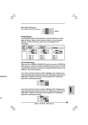
... very high. Please refer to below to set up the jumpers. Please follow the instructions below jumper settings. Please refer to below jumper settings. 15 ASRock G41M-GS Motherboard English DRAM CPU Jumper Settings DDR2 533 FSB533 DDR2 1066 FSB1066 FSB1333 FSB1: 2-3 FSB2: 1-2 FSB3: 2-3 FSB1: 1-2 FSB2: 1-2 FSB3: 2-3 FSB1: 1-2 FSB2: 4-5 FSB3: 1-2 Overclocking Setting: When...
... very high. Please refer to below to set up the jumpers. Please follow the instructions below jumper settings. Please refer to below jumper settings. 15 ASRock G41M-GS Motherboard English DRAM CPU Jumper Settings DDR2 533 FSB533 DDR2 1066 FSB1066 FSB1333 FSB1: 2-3 FSB2: 1-2 FSB3: 2-3 FSB1: 1-2 FSB2: 1-2 FSB3: 2-3 FSB1: 1-2 FSB2: 4-5 FSB3: 1-2 Overclocking Setting: When...

Quick Installation Guide
Page 16
... cable to 3.0 Gb/s data transfer rate. Do NOT place jumper caps over the headers and connectors will cause permanent damage of the power supply. 16 ASRock G41M-GS Motherboard English 2.6 Onboard Headers and Connectors Onboard headers and connectors are NOT jumpers. Placing jumper caps over these headers and connectors.
... cable to 3.0 Gb/s data transfer rate. Do NOT place jumper caps over the headers and connectors will cause permanent damage of the power supply. 16 ASRock G41M-GS Motherboard English 2.6 Onboard Headers and Connectors Onboard headers and connectors are NOT jumpers. Placing jumper caps over these headers and connectors.

Quick Installation Guide
Page 17
... Utility. F. USB 2.0 Headers (9-pin USB6_7) (see p.2 No. 15) (9-pin USB4_5) (see p.2 No. 16) Besides four default USB 2.0 ports on the I /O", select "Connector Settings" , choose 17 ASRock G41M-GS Motherboard English Each USB 2.0 header can support two USB 2.0 ports. B. Click the icon on the lower right hand taskbar to MIC2_L. Front Panel Audio Header...
... Utility. F. USB 2.0 Headers (9-pin USB6_7) (see p.2 No. 15) (9-pin USB4_5) (see p.2 No. 16) Besides four default USB 2.0 ports on the I /O", select "Connector Settings" , choose 17 ASRock G41M-GS Motherboard English Each USB 2.0 header can support two USB 2.0 ports. B. Click the icon on the lower right hand taskbar to MIC2_L. Front Panel Audio Header...

Quick Installation Guide
Page 18
... record device. System Panel Header (9-pin PANEL1) (see p.2 No. 4) 4 3 2 1 Please connect the chassis speaker to the ground pin. Pin 1-3 Connected 3-Pin Fan Installation English 18 ASRock G41M-GS Motherboard If you plan to connect the 3-Pin CPU fan to the CPU fan connector on this motherboard provides 4-Pin CPU fan (Quiet Fan) support...
... record device. System Panel Header (9-pin PANEL1) (see p.2 No. 4) 4 3 2 1 Please connect the chassis speaker to the ground pin. Pin 1-3 Connected 3-Pin Fan Installation English 18 ASRock G41M-GS Motherboard If you plan to connect the 3-Pin CPU fan to the CPU fan connector on this motherboard provides 4-Pin CPU fan (Quiet Fan) support...

Quick Installation Guide
Page 19
English tion 19 ASRock G41M-GS Motherboard To use the 20-pin ATX power supply, please plug your power supply along with ATX 12V plug to this motherboard provides 24-pin ...
English tion 19 ASRock G41M-GS Motherboard To use the 20-pin ATX power supply, please plug your power supply along with ATX 12V plug to this motherboard provides 24-pin ...


