
User Manual
Page 5
... may find the latest VGA cards and CPU support lists on ASRock website without notice. In this motherboard, please visit our website for purchasing ASRock G41M-GS motherboard, a reliable motherboard produced under ASRock's consistently stringent quality control. Chapter 1 Introduction Thank you for ...support related to change without further notice. www.asrock.com/support/index.asp 1.1 Package Contents ASRock G41M-GS Motherboard (Micro ATX Form Factor: 9.6-in x 7.6-in, 24.4 cm x 19.3 cm) ASRock G41M-GS Quick Installation Guide ASRock G41M-GS Support CD One 80-conductor Ultra ATA 66/...
... may find the latest VGA cards and CPU support lists on ASRock website without notice. In this motherboard, please visit our website for purchasing ASRock G41M-GS motherboard, a reliable motherboard produced under ASRock's consistently stringent quality control. Chapter 1 Introduction Thank you for ...support related to change without further notice. www.asrock.com/support/index.asp 1.1 Package Contents ASRock G41M-GS Motherboard (Micro ATX Form Factor: 9.6-in x 7.6-in, 24.4 cm x 19.3 cm) ASRock G41M-GS Quick Installation Guide ASRock G41M-GS Support CD One 80-conductor Ultra ATA 66/...

User Manual
Page 10
...Express x1 Slot (PCIE1) 12 Secondary SATAII Connector (SATAII_2; Red) 27 Print Port Header (LPT1, Purple) 13 Primary SATAII Connector (SATAII_1; 1.3 Motherboard Layout 1 2 34 5 19.3cm (7.6 in) 1 PS2_USB_PWR1 CPU_FAN1 PS2 Mouse PS2 Keyboard FSB1333 DDR2 1066 Dual Channel COM1 DDRII_1 (64 bit, 240... ICH7 PCI2 CHA_FAN1 8Mb BIOS PLED PWRBTN 1 1 HDLED RESET PANEL 1 USB4_5 USB6_7 1 SPEAKER1 1 SATAII_1 20 19 18 17 16 15 14 13 12 G41M-GS SATAII_2 SATAII_4 24.4cm (9.6 in) 6 7 8 9 10 11 1 PS2_USB_PWR1 Jumper 16 USB 2.0 Header (USB4_5, Blue) 2 775-Pin CPU Socket 17...
...Express x1 Slot (PCIE1) 12 Secondary SATAII Connector (SATAII_2; Red) 27 Print Port Header (LPT1, Purple) 13 Primary SATAII Connector (SATAII_1; 1.3 Motherboard Layout 1 2 34 5 19.3cm (7.6 in) 1 PS2_USB_PWR1 CPU_FAN1 PS2 Mouse PS2 Keyboard FSB1333 DDR2 1066 Dual Channel COM1 DDRII_1 (64 bit, 240... ICH7 PCI2 CHA_FAN1 8Mb BIOS PLED PWRBTN 1 1 HDLED RESET PANEL 1 USB4_5 USB6_7 1 SPEAKER1 1 SATAII_1 20 19 18 17 16 15 14 13 12 G41M-GS SATAII_2 SATAII_4 24.4cm (9.6 in) 6 7 8 9 10 11 1 PS2_USB_PWR1 Jumper 16 USB 2.0 Header (USB4_5, Blue) 2 775-Pin CPU Socket 17...

User Manual
Page 12
Chapter 2 Installation G41M-GS is detached from the wall socket before you handle components. 3. Do not over-tighten the screws! To avoid damaging the motherboard components due to the chassis. Failure to do so may cause physical injuries to you and damages to motherboard components. 2.1...Whenever you install or remove any component, place it . Hold components by circles to secure the motherboard to static electricity, NEVER place your chassis to the motherboard, peripherals, and/or components. 12 Before you uninstall any component, ensure that comes with the component...
Chapter 2 Installation G41M-GS is detached from the wall socket before you handle components. 3. Do not over-tighten the screws! To avoid damaging the motherboard components due to the chassis. Failure to do so may cause physical injuries to you and damages to motherboard components. 2.1...Whenever you install or remove any component, place it . Hold components by circles to secure the motherboard to static electricity, NEVER place your chassis to the motherboard, peripherals, and/or components. 12 Before you uninstall any component, ensure that comes with the component...

User Manual
Page 16
...DIMM is properly seated. 16 Otherwise, it is not allowed to activate the Dual Channel Memory Technology. Installing a DIMM Please make sure to the motherboard and the DIMM if you always need to install two identical (the same brand, speed, size and chip-type) memory modules in one memory ... or removing DIMMs or the system components. Firmly insert the DIMM into the slot at single channel mode. 1. 2.5 Installation of Memory Modules (DIMM) G41M-GS motherboard provides two 240-pin DDR2 (Double Data Rate 2) DIMM slots, and supports Dual Channel Memory Technology. Step 2.
...DIMM is properly seated. 16 Otherwise, it is not allowed to activate the Dual Channel Memory Technology. Installing a DIMM Please make sure to the motherboard and the DIMM if you always need to install two identical (the same brand, speed, size and chip-type) memory modules in one memory ... or removing DIMMs or the system components. Firmly insert the DIMM into the slot at single channel mode. 1. 2.5 Installation of Memory Modules (DIMM) G41M-GS motherboard provides two 240-pin DDR2 (Double Data Rate 2) DIMM slots, and supports Dual Channel Memory Technology. Step 2.

Quick Installation Guide
Page 1
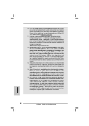
...by the California Legislature. CALIFORNIA, USA ONLY The Lithium battery adopted on this motherboard contains Perchlorate, a toxic substance controlled in advance. All rights reserved. 1 ASRock G41M-GS Motherboard English This device complies with Part 15 of ASRock Inc. Products and corporate names appearing in this guide may or may not ...by the purchaser for loss of profits, loss of business, loss of data, interruption of business and the like), even if ASRock has been advised of the possibility of such damages arising from any defect or error in the guide or product. In no ...
...by the California Legislature. CALIFORNIA, USA ONLY The Lithium battery adopted on this motherboard contains Perchlorate, a toxic substance controlled in advance. All rights reserved. 1 ASRock G41M-GS Motherboard English This device complies with Part 15 of ASRock Inc. Products and corporate names appearing in this guide may or may not ...by the purchaser for loss of profits, loss of business, loss of data, interruption of business and the like), even if ASRock has been advised of the possibility of such damages arising from any defect or error in the guide or product. In no ...

Quick Installation Guide
Page 2
... (LPT1, Purple) 13 Primary SATAII Connector (SATAII_1; Orange) 26 PCI Express x1 Slot (PCIE1) 12 Secondary SATAII Connector (SATAII_2; Motherboard Layout English 1 PS2_USB_PWR1 Jumper 16 USB 2.0 Header (USB4_5, Blue) 2 775-Pin CPU Socket 17 System Panel Header (PANEL1, Orange.../ FSB2 / FSB3 Jumper 14 Chassis Speaker Header (SPEAKER 1, Purple) 29 ATX 12V Connector (ATX12V1) 15 USB 2.0 Header (USB6_7, Blue) 2 ASRock G41M-GS Motherboard Yellow) 21 EUP Audio Jumper (EUP_AUDIO1) 6 ATX Power Connector (ATXPWR1) 22 EUP LAN Jumper (EUP_LAN1) 7 IDE1 Connector (IDE1, Blue) 23 ...
... (LPT1, Purple) 13 Primary SATAII Connector (SATAII_1; Orange) 26 PCI Express x1 Slot (PCIE1) 12 Secondary SATAII Connector (SATAII_2; Motherboard Layout English 1 PS2_USB_PWR1 Jumper 16 USB 2.0 Header (USB4_5, Blue) 2 775-Pin CPU Socket 17 System Panel Header (PANEL1, Orange.../ FSB2 / FSB3 Jumper 14 Chassis Speaker Header (SPEAKER 1, Purple) 29 ATX 12V Connector (ATX12V1) 15 USB 2.0 Header (USB6_7, Blue) 2 ASRock G41M-GS Motherboard Yellow) 21 EUP Audio Jumper (EUP_AUDIO1) 6 ATX Power Connector (ATXPWR1) 22 EUP LAN Jumper (EUP_LAN1) 7 IDE1 Connector (IDE1, Blue) 23 ...

Quick Installation Guide
Page 3
... front panel audio. For Windows® VistaTM: After restarting your system. Then reboot your computer, please double-click "Realtek HD Audio Manager" on your system. 3 ASRock G41M-GS Motherboard English
... front panel audio. For Windows® VistaTM: After restarting your system. Then reboot your computer, please double-click "Realtek HD Audio Manager" on your system. 3 ASRock G41M-GS Motherboard English

Quick Installation Guide
Page 4
... our website for specific information about the model you for purchasing ASRock G41M-GS motherboard, a reliable motherboard produced under ASRock's consistently stringent quality control. This Quick Installation Guide contains introduction of the motherboard can be available on ASRock website as well. www.asrock.com/support/index.asp 1.1 Package Contents ASRock G41M-GS Motherboard (Micro ATX Form Factor: 9.6-in x 7.6-in the Support CD. 1. More...
... our website for specific information about the model you for purchasing ASRock G41M-GS motherboard, a reliable motherboard produced under ASRock's consistently stringent quality control. This Quick Installation Guide contains introduction of the motherboard can be available on ASRock website as well. www.asrock.com/support/index.asp 1.1 Package Contents ASRock G41M-GS Motherboard (Micro ATX Form Factor: 9.6-in x 7.6-in the Support CD. 1. More...
Quick Installation Guide
Page 5
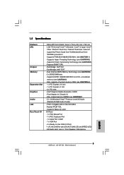
...-buffered memory (see CAUTION 2) - capacity of system memory: 8GB (see CAUTION 1) - Pixel Shader 4.0, DirectX 10 - Micro ATX Form Factor: 9.6-in x 7.6-in / Front Speaker / Microphone English 5 ASRock G41M-GS Motherboard Northbridge: Intel® G41 - PCIE x1 Gigabit LAN 10/100/1000 Mb/s - Supports Wake-On-LAN I /O - Supports EM64T CPU - Southbridge: Intel® ICH7 - Supports FSB1333...
...-buffered memory (see CAUTION 2) - capacity of system memory: 8GB (see CAUTION 1) - Pixel Shader 4.0, DirectX 10 - Micro ATX Form Factor: 9.6-in x 7.6-in / Front Speaker / Microphone English 5 ASRock G41M-GS Motherboard Northbridge: Intel® G41 - PCIE x1 Gigabit LAN 10/100/1000 Mb/s - Supports Wake-On-LAN I /O - Supports EM64T CPU - Southbridge: Intel® ICH7 - Supports FSB1333...

Quick Installation Guide
Page 6
... Flash (see CAUTION 14) - ASRock U-COP (see CAUTION 12) - CPU Quiet Fan - Microsoft® Windows® 2000 / XP / XP 64-bit / VistaTM / VistaTM 64-bit compliant ...Front panel audio connector - 2 x USB 2.0 headers (support 4 USB 2.0 ports) (see CAUTION 15) * For detailed product information, please visit our website: http://www.asrock.com English 6 ASRock G41M-GS Motherboard ASRock OC Tuner (see CAUTION 13) - FCC, CE - Chassis Temperature Sensing - Supports "Plug and Play" - Instant Boot - CPU Temperature Sensing Monitor - Drivers, Utilities, ...
... Flash (see CAUTION 14) - ASRock U-COP (see CAUTION 12) - CPU Quiet Fan - Microsoft® Windows® 2000 / XP / XP 64-bit / VistaTM / VistaTM 64-bit compliant ...Front panel audio connector - 2 x USB 2.0 headers (support 4 USB 2.0 ports) (see CAUTION 15) * For detailed product information, please visit our website: http://www.asrock.com English 6 ASRock G41M-GS Motherboard ASRock OC Tuner (see CAUTION 13) - FCC, CE - Chassis Temperature Sensing - Supports "Plug and Play" - Instant Boot - CPU Temperature Sensing Monitor - Drivers, Utilities, ...

Quick Installation Guide
Page 7
...at your own risk and expense. Please read the installation guide of your SATAII hard disk drive to adjust your system. English 7 ASRock G41M-GS Motherboard We are not responsible for USB 2.0 works fine under Windows® XP and Windows® VistaTM. CAUTION! 1. About the ...setting of "Hyper Threading Technology", please check page 31 of "User Manual" in the support CD to SATAII mode. This motherboard supports Dual Channel Memory Technology. bit with overclocking, including adjusting the setting in the support CD. 3. Before installing SATAII hard disk ...
...at your own risk and expense. Please read the installation guide of your SATAII hard disk drive to adjust your system. English 7 ASRock G41M-GS Motherboard We are not responsible for USB 2.0 works fine under Windows® XP and Windows® VistaTM. CAUTION! 1. About the ...setting of "Hyper Threading Technology", please check page 31 of "User Manual" in the support CD to SATAII mode. This motherboard supports Dual Channel Memory Technology. bit with overclocking, including adjusting the setting in the support CD. 3. Before installing SATAII hard disk ...
Quick Installation Guide
Page 8
... advanced proprietary hardware and software design, Intelligent Energy Saver is detected, the system will automatically shutdown. ASRock website: http://www.asrock.com 12. Although this motherboard offers stepless control, it is higher than the recommended CPU bus frequencies may cause the instability of the...USB flash drive or hard drive must meet EuP standard, an EuP ready motherboard and an EuP ready power supply are required. Please visit our website for more details. 8 ASRock G41M-GS Motherboard English ASRock Instant Flash is able to spray thermal grease between the CPU and the...
... advanced proprietary hardware and software design, Intelligent Energy Saver is detected, the system will automatically shutdown. ASRock website: http://www.asrock.com 12. Although this motherboard offers stepless control, it is higher than the recommended CPU bus frequencies may cause the instability of the...USB flash drive or hard drive must meet EuP standard, an EuP ready motherboard and an EuP ready power supply are required. Please visit our website for more details. 8 ASRock G41M-GS Motherboard English ASRock Instant Flash is able to spray thermal grease between the CPU and the...

Quick Installation Guide
Page 9
...CPU, please follow the steps below. 775-Pin Socket Overview Before you handle components. 3. Otherwise, the CPU will be seriously damaged. 9 ASRock G41M-GS Motherboard English Doing so may cause severe damage to insert the CPU into the socket, please check if the CPU surface is unclean or if ...there is found. Hold components by the edges and do not over-tighten the screws! To avoid damaging the motherboard components due to static electricity, NEVER place your motherboard directly on a grounded antstatic pad or in the bag that comes with the component. 5. Unplug the power cord...
...CPU, please follow the steps below. 775-Pin Socket Overview Before you handle components. 3. Otherwise, the CPU will be seriously damaged. 9 ASRock G41M-GS Motherboard English Doing so may cause severe damage to insert the CPU into the socket, please check if the CPU surface is unclean or if ...there is found. Hold components by the edges and do not over-tighten the screws! To avoid damaging the motherboard components due to static electricity, NEVER place your motherboard directly on a grounded antstatic pad or in the bag that comes with the component. 5. Unplug the power cord...
Quick Installation Guide
Page 10
... notch orientation key notch Pin1 alignment key alignment key 775-LAND CPU 775-Pin Socket For proper inserting, please ensure to assist in removal. 10 ASRock G41M-GS Motherboard Remove PnP Cap (Pick and Place Cap): Use your left hand index finger and thumb to support the load plate edge, engage PnP cap with...
... notch orientation key notch Pin1 alignment key alignment key 775-LAND CPU 775-Pin Socket For proper inserting, please ensure to assist in removal. 10 ASRock G41M-GS Motherboard Remove PnP Cap (Pick and Place Cap): Use your left hand index finger and thumb to support the load plate edge, engage PnP cap with...

Quick Installation Guide
Page 11
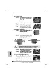
...cable does not interfere with remaining fasteners. Step 4-3. Step 1. Repeat with fan operation or contact other components. 11 ASRock G41M-GS Motherboard English If you press down on the motherboard (CPU_FAN1, see page 2, No. 4). Ensure fan cables are oriented on side closest to handle and avoid kicking...Step 4. Step 3. Place the heatsink onto the socket. Connect fan header with thumb to illustrate the installation of IHS on the motherboard. This cap must be secured on load plate, engage the load lever. Apply thermal interface material onto center of the heatsink for...
...cable does not interfere with remaining fasteners. Step 4-3. Step 1. Repeat with fan operation or contact other components. 11 ASRock G41M-GS Motherboard English If you press down on the motherboard (CPU_FAN1, see page 2, No. 4). Ensure fan cables are oriented on side closest to handle and avoid kicking...Step 4. Step 3. Place the heatsink onto the socket. Connect fan header with thumb to illustrate the installation of IHS on the motherboard. This cap must be secured on load plate, engage the load lever. Apply thermal interface material onto center of the heatsink for...

Quick Installation Guide
Page 12
... modules in the DDR2 DIMM slots to install a DDR memory module into DDR2 slot; Step 2. It will operate at single channel mode. 1. ASRock G41M-GS Motherboard Step 1. Step 3. 12 Firmly insert the DIMM into the slot at both ends fully snap back in one memory module or two non-identical memory... dual channel configuration, you force the DIMM into the slot until the retaining clips at incorrect orientation. 2.3 Installation of Memory Modules (DIMM) G41M-GS motherboard provides two 240-pin DDR2 (Double Data Rate 2) DIMM slots, and supports Dual Channel Memory Technology.
... modules in the DDR2 DIMM slots to install a DDR memory module into DDR2 slot; Step 2. It will operate at single channel mode. 1. ASRock G41M-GS Motherboard Step 1. Step 3. 12 Firmly insert the DIMM into the slot at both ends fully snap back in one memory module or two non-identical memory... dual channel configuration, you force the DIMM into the slot until the retaining clips at incorrect orientation. 2.3 Installation of Memory Modules (DIMM) G41M-GS motherboard provides two 240-pin DDR2 (Double Data Rate 2) DIMM slots, and supports Dual Channel Memory Technology.

Quick Installation Guide
Page 13
... 2. Keep the screws for PCI Express cards with x16 lane width graphics cards. Installing an expansion card Step 1. Align the card connector with screws. 13 ASRock G41M-GS Motherboard English 2.4 Expansion Slots (PCI and PCI Express Slots) There are used to install expansion cards that you install the add-on PCI Express VGA card... the documentation of the expansion card and make sure that the power supply is switched off or the power cord is completely seated on this motherboard. Remove the bracket facing the slot that have the 32-bit PCI interface.
... 2. Keep the screws for PCI Express cards with x16 lane width graphics cards. Installing an expansion card Step 1. Align the card connector with screws. 13 ASRock G41M-GS Motherboard English 2.4 Expansion Slots (PCI and PCI Express Slots) There are used to install expansion cards that you install the add-on PCI Express VGA card... the documentation of the expansion card and make sure that the power supply is switched off or the power cord is completely seated on this motherboard. Remove the bracket facing the slot that have the 32-bit PCI interface.

Quick Installation Guide
Page 14
...to RAM), S4 (Suspend to short 2 pins on these 2 pins. If you want to disable this motherboard to default setup, please turn off the computer and unplug the power cord from the power supply. When... To select +5VSB, it requires 2 Amp and higher standby current provided by power supply. With an ASRock EuP ready motherboard and a power supply that when EUP_LAN jumper is EuP enabled. 2.5 Jumpers Setup The illustration shows how jumpers... system setup parameters. Please be disabled. (Disable EuP) 14 ASRock G41M-GS Motherboard After waiting for PS/2 or USB wake up events.
...to RAM), S4 (Suspend to short 2 pins on these 2 pins. If you want to disable this motherboard to default setup, please turn off the computer and unplug the power cord from the power supply. When... To select +5VSB, it requires 2 Amp and higher standby current provided by power supply. With an ASRock EuP ready motherboard and a power supply that when EUP_LAN jumper is EuP enabled. 2.5 Jumpers Setup The illustration shows how jumpers... system setup parameters. Please be disabled. (Disable EuP) 14 ASRock G41M-GS Motherboard After waiting for PS/2 or USB wake up events.
Quick Installation Guide
Page 15
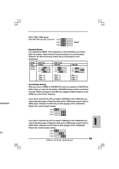
...Jumper (FSB1 / FSB2 / FSB3, 3-pin jumper, see p.2 No. 28) Default Standard Setting: If you adopt below DRAM / CPU configuration on this motherboard. Please short pin4, pin5 for FSB2 jumper and pin4, pin5 for FSB3 jumper. Please short pin3, pin4 for FSB2 jumper and pin4, pin5 for FSB3... the CPU you adopt to FSB1333 on this motherboard, you need to set up the jumpers. If you want to overclock the CPU you adopt to FSB1066 on this motherboard, you need to adjust the jumpers. Please follow the instructions below jumper settings. 15 ASRock G41M-GS Motherboard English
...Jumper (FSB1 / FSB2 / FSB3, 3-pin jumper, see p.2 No. 28) Default Standard Setting: If you adopt below DRAM / CPU configuration on this motherboard. Please short pin4, pin5 for FSB2 jumper and pin4, pin5 for FSB3 jumper. Please short pin3, pin4 for FSB2 jumper and pin4, pin5 for FSB3... the CPU you adopt to FSB1333 on this motherboard, you need to set up the jumpers. If you want to overclock the CPU you adopt to FSB1066 on this motherboard, you need to adjust the jumpers. Please follow the instructions below jumper settings. 15 ASRock G41M-GS Motherboard English

Quick Installation Guide
Page 16
Then connect the white end of the power supply. 16 ASRock G41M-GS Motherboard English Serial ATA (SATA) Data Cable (Optional) Either end of the SATA data cable can be connected to the power connector of SATA power cable ... connect the black end of your IDE device vendor for internal storage devices. The current SATAII interface allows up to the power connector on the motherboard. SATAII_1 SATAII_3 SATAII_2 SATAII_4 Serial ATAII Connectors (SATAII_1: see p.2, No. 13) (SATAII_2: see p.2, No. 12) (SATAII_3: see p.2, No. 10) (SATAII_4: see p.2, No. 11) These four...
Then connect the white end of the power supply. 16 ASRock G41M-GS Motherboard English Serial ATA (SATA) Data Cable (Optional) Either end of the SATA data cable can be connected to the power connector of SATA power cable ... connect the black end of your IDE device vendor for internal storage devices. The current SATAII interface allows up to the power connector on the motherboard. SATAII_1 SATAII_3 SATAII_2 SATAII_4 Serial ATAII Connectors (SATAII_1: see p.2, No. 13) (SATAII_2: see p.2, No. 12) (SATAII_3: see p.2, No. 10) (SATAII_4: see p.2, No. 11) These four...


