
User Manual
Page 3
... 1.3 Motherboard Layout 10 1.4 I/O Panel 11 2 Installation 12 2.1 Screw Holes 12 2.2 Pre-installation Precautions 12 2.3 CPU Installation 13 2.4 Installation of Heatsink and CPU fan 15 2.5 Installation of Memory Modules (DIMM 16 2.6 Expansion Slots (PCI and PCI Express Slots 17 2.7 Jumpers...26 3.1.1 BIOS Menu Bar 26 3.1.2 Navigation Keys 27 3.2 Main Screen 27 3.3 Smart Screen 28 3.4 Advanced Screen 29 3.4.1 CPU Configuration 30 3.4.2 Chipset Configuration 32 3.4.3 ACPI Configuration 40 3.4.4 IDE Configuration 41 3.4.5 PCIPnP Configuration 43 3.4.6 Floppy Configuration 44 ...
... 1.3 Motherboard Layout 10 1.4 I/O Panel 11 2 Installation 12 2.1 Screw Holes 12 2.2 Pre-installation Precautions 12 2.3 CPU Installation 13 2.4 Installation of Heatsink and CPU fan 15 2.5 Installation of Memory Modules (DIMM 16 2.6 Expansion Slots (PCI and PCI Express Slots 17 2.7 Jumpers...26 3.1.1 BIOS Menu Bar 26 3.1.2 Navigation Keys 27 3.2 Main Screen 27 3.3 Smart Screen 28 3.4 Advanced Screen 29 3.4.1 CPU Configuration 30 3.4.2 Chipset Configuration 32 3.4.3 ACPI Configuration 40 3.4.4 IDE Configuration 41 3.4.5 PCIPnP Configuration 43 3.4.6 Floppy Configuration 44 ...

User Manual
Page 5
...will be subject to the hardware installation. www.asrock.com/support/index.asp 1.1 Package Contents ASRock G41M-GS Motherboard (Micro ATX Form Factor: 9.6-in x 7.6-in, 24.4 cm x 19.3 cm) ASRock G41M-GS Quick Installation Guide ASRock G41M-GS Support CD One 80-conductor Ultra ATA 66/... the model you for purchasing ASRock G41M-GS motherboard, a reliable motherboard produced under ASRock's consistently stringent quality control. You may find the latest VGA cards and CPU support lists on ASRock website without notice. ASRock website http://www.asrock.com If you require technical ...
...will be subject to the hardware installation. www.asrock.com/support/index.asp 1.1 Package Contents ASRock G41M-GS Motherboard (Micro ATX Form Factor: 9.6-in x 7.6-in, 24.4 cm x 19.3 cm) ASRock G41M-GS Quick Installation Guide ASRock G41M-GS Support CD One 80-conductor Ultra ATA 66/... the model you for purchasing ASRock G41M-GS motherboard, a reliable motherboard produced under ASRock's consistently stringent quality control. You may find the latest VGA cards and CPU support lists on ASRock website without notice. ASRock website http://www.asrock.com If you require technical ...
User Manual
Page 6
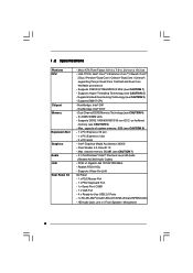
... 24.4 cm x 19.3 cm - Pixel Shader 4.0, DirectX 10 - Micro ATX Form Factor: 9.6-in x 7.6-in / Front Speaker / Microphone 6 Supports EM64T CPU - Dual Channel DDR2 Memory Technology (see CAUTION 6) - 1 x PCI Express x16 slot - 1 x PCI Express x1 slot - 2 x PCI slots - shared... 352MB (see CAUTION 7) - 5.1 CH Windows® VistaTM Premium Level HD Audio (Realtek ALC662 Audio Codec) - Southbridge: Intel® ICH7 - 1.2 Specifications Platform CPU Chipset Memory Expansion Slot Graphics Audio LAN Rear Panel I /O Panel - 1 x PS/2 Mouse Port - 1 x PS/2 Keyboard Port - 1 x Serial Port:...
... 24.4 cm x 19.3 cm - Pixel Shader 4.0, DirectX 10 - Micro ATX Form Factor: 9.6-in x 7.6-in / Front Speaker / Microphone 6 Supports EM64T CPU - Dual Channel DDR2 Memory Technology (see CAUTION 6) - 1 x PCI Express x16 slot - 1 x PCI Express x1 slot - 2 x PCI slots - shared... 352MB (see CAUTION 7) - 5.1 CH Windows® VistaTM Premium Level HD Audio (Realtek ALC662 Audio Codec) - Southbridge: Intel® ICH7 - 1.2 Specifications Platform CPU Chipset Memory Expansion Slot Graphics Audio LAN Rear Panel I /O Panel - 1 x PS/2 Mouse Port - 1 x PS/2 Keyboard Port - 1 x Serial Port:...

User Manual
Page 7
... (B.F.G.) Hardware - Microsoft® Windows® 2000 / XP / XP 64-bit / VistaTM / VistaTM 64-bit compliant Certifications - AMI Legal BIOS - AMBIOS 2.3.1 Support - ASRock OC Tuner (see CAUTION 11) - CPU Fan Tachometer - CPU Quiet Fan - Voltage Monitoring: +12V, +5V, +3.3V, Vcore OS - Supports "Plug and Play" - Drivers, Utilities, AntiVirus Software (Trial Version) Unique Feature - Chassis...
... (B.F.G.) Hardware - Microsoft® Windows® 2000 / XP / XP 64-bit / VistaTM / VistaTM 64-bit compliant Certifications - AMI Legal BIOS - AMBIOS 2.3.1 Support - ASRock OC Tuner (see CAUTION 11) - CPU Fan Tachometer - CPU Quiet Fan - Voltage Monitoring: +12V, +5V, +3.3V, Vcore OS - Supports "Plug and Play" - Drivers, Utilities, AntiVirus Software (Trial Version) Unique Feature - Chassis...
User Manual
Page 8
... Technology. The maximum shared memory size is a user-friendly ASRock overclocking tool which allows you do not need to change. It is defined by overclocking. Please check Intel® website for the CPU FSB frequency and its corresponding memory support frequency. CAUTION! 1.... You can also connect SATA hard disk to page 19 for USB 2.0 works fine under Windows® environment. ASRock website: http://www.asrock.com 8 For special overclocking mode...
... Technology. The maximum shared memory size is a user-friendly ASRock overclocking tool which allows you do not need to change. It is defined by overclocking. Please check Intel® website for the CPU FSB frequency and its corresponding memory support frequency. CAUTION! 1.... You can also connect SATA hard disk to page 19 for USB 2.0 works fine under Windows® environment. ASRock website: http://www.asrock.com 8 For special overclocking mode...

User Manual
Page 9
...key to BIOS setup menu to spray thermal grease between the CPU and the heatsink when you can update your BIOS only in off mode condition. To improve heat dissipation, remember to access ASRock Instant Flash. According to provide exceptional power saving and improve ...power efficiency without entering operating systems first like MS-DOS or Windows®. While CPU overheat is higher than the recommended CPU bus frequencies may cause the instability of...
...key to BIOS setup menu to spray thermal grease between the CPU and the heatsink when you can update your BIOS only in off mode condition. To improve heat dissipation, remember to access ASRock Instant Flash. According to provide exceptional power saving and improve ...power efficiency without entering operating systems first like MS-DOS or Windows®. While CPU overheat is higher than the recommended CPU bus frequencies may cause the instability of...

User Manual
Page 10
...USB4_5 USB6_7 1 SPEAKER1 1 SATAII_1 20 19 18 17 16 15 14 13 12 G41M-GS SATAII_2 SATAII_4 24.4cm (9.6 in) 6 7 8 9 10 11 1 PS2_USB_PWR1 Jumper 16 USB 2.0 Header (USB4_5, Blue) 2 775-Pin CPU Socket 17 System Panel Header (PANEL1, Orange) 3 North Bridge Controller 18 BIOS ...SPI Chip 4 CPU Fan Connector (CPU_FAN1) 19 Chassis Fan Connector (CHA_FAN1) 5 2 x 240-pin DDR2 DIMM Slots 20 Floppy Connector...
...USB4_5 USB6_7 1 SPEAKER1 1 SATAII_1 20 19 18 17 16 15 14 13 12 G41M-GS SATAII_2 SATAII_4 24.4cm (9.6 in) 6 7 8 9 10 11 1 PS2_USB_PWR1 Jumper 16 USB 2.0 Header (USB4_5, Blue) 2 775-Pin CPU Socket 17 System Panel Header (PANEL1, Orange) 3 North Bridge Controller 18 BIOS ...SPI Chip 4 CPU Fan Connector (CPU_FAN1) 19 Chassis Fan Connector (CHA_FAN1) 5 2 x 240-pin DDR2 DIMM Slots 20 Floppy Connector...

User Manual
Page 13
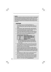
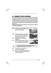
... key notches. Pin1 orientation key notch orientation key notch Pin1 alignment key alignment key 775-LAND CPU 775-Pin Socket 13 black line black line Step 2-2. Insert the 775-LAND CPU: Step 2-1. Step 1-3. DLifitsLeevnergUapgtoin9g0° the lever by the edges where are marked with IHS... force to fully open position at approximately 135 degrees. 2.3 CPU Installation For the installation of Intel 775-LAND CPU, please follow the steps below. 775-Pin Socket Overview Before you insert the 775-LAND CPU into the socket if above situation is any bent pin on...
... key notches. Pin1 orientation key notch orientation key notch Pin1 alignment key alignment key 775-LAND CPU 775-Pin Socket 13 black line black line Step 2-2. Insert the 775-LAND CPU: Step 2-1. Step 1-3. DLifitsLeevnergUapgtoin9g0° the lever by the edges where are marked with IHS... force to fully open position at approximately 135 degrees. 2.3 CPU Installation For the installation of Intel 775-LAND CPU, please follow the steps below. 775-Pin Socket Overview Before you insert the 775-LAND CPU into the socket if above situation is any bent pin on...
User Manual
Page 14
Verify that the CPU is recommended to use the cap tab to handle and avoid kicking off the PnP cap. 2. Step 4. Close the socket: Step 4-1. Step 4-3. Rotate the load .... 14 Step 4-2. Step 2-4. Remove PnP Cap (Pick and Place Cap): Use your left hand index finger and thumb to the orient keys. Carefully place the CPU into the socket by using a purely vertical motion. Step 3. This cap must be placed if returning the motherboard for after service. While pressing down lightly...
Verify that the CPU is recommended to use the cap tab to handle and avoid kicking off the PnP cap. 2. Step 4. Close the socket: Step 4-1. Step 4-3. Rotate the load .... 14 Step 4-2. Step 2-4. Remove PnP Cap (Pick and Place Cap): Use your left hand index finger and thumb to the orient keys. Carefully place the CPU into the socket by using a purely vertical motion. Step 3. This cap must be placed if returning the motherboard for after service. While pressing down lightly...
User Manual
Page 15
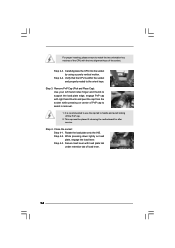
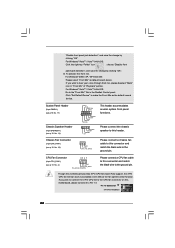
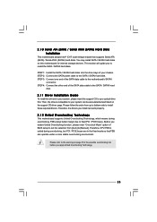
...15 Step 2. Ensure fan cables are securely fastened and in good contact with 775-Pin socket that the CPU and the heatsink are oriented on side closest to the CPU fan connector on the socket surface. Please adopt the type of heatsink and cooling fan compliant with remaining ...motherboard throughholes. Apply thermal interface material onto center of IHS on the motherboard (CPU_FAN1, see page 10, No. 4). Repeat with Intel 775-LAND CPU to dissipate heat. Step 5. Connect fan header with thumb to install and lock. Step 1. Rotate the fastener clockwise, then press down the fasteners...
...15 Step 2. Ensure fan cables are securely fastened and in good contact with 775-Pin socket that the CPU and the heatsink are oriented on side closest to the CPU fan connector on the socket surface. Please adopt the type of heatsink and cooling fan compliant with remaining ...motherboard throughholes. Apply thermal interface material onto center of IHS on the motherboard (CPU_FAN1, see page 10, No. 4). Repeat with Intel 775-LAND CPU to dissipate heat. Step 5. Connect fan header with thumb to install and lock. Step 1. Rotate the fastener clockwise, then press down the fasteners...

User Manual
Page 19
...the instructions below to be overclocked very high. Please short pin3, pin4 for FSB2 jumper and pin4, pin5 for FSB3 jumper. Otherwise, the CPU may face the problem, that DRAM frequency will be strapped at higher frequency, so the DRAM can work properly on this motherboard. FSB1 FSB2 ...FSB3 19 Please refer to FSB1333 (by BIOS setting) you may not work at lower frequency. Otherwise, the CPU may not work properly on this motherboard. DRAM CPU Jumper Settings DDR2 533 FSB533 FSB1 FSB2 FSB3 DDR2 1066 FSB1066 FSB1 FSB2 FSB3 FSB1333 FSB1 FSB2 FSB3 FSB1: 2-3 FSB2: ...
...the instructions below to be overclocked very high. Please short pin3, pin4 for FSB2 jumper and pin4, pin5 for FSB3 jumper. Otherwise, the CPU may face the problem, that DRAM frequency will be strapped at higher frequency, so the DRAM can work properly on this motherboard. FSB1 FSB2 ...FSB3 19 Please refer to FSB1333 (by BIOS setting) you may not work at lower frequency. Otherwise, the CPU may not work properly on this motherboard. DRAM CPU Jumper Settings DDR2 533 FSB533 FSB1 FSB2 FSB3 DDR2 1066 FSB1066 FSB1 FSB2 FSB3 FSB1333 FSB1 FSB2 FSB3 FSB1: 2-3 FSB2: ...
User Manual
Page 22
... 1) (see p.10 No. 14) Chassis Fan Connector (3-pin CHA_FAN1) (see p.10 No. 4) 4 3 2 1 GND +12V CPU_FAN_SPEED FAN_SPEED_CONTROL Please connect a CPU fan cable to this connector and match the black wire to make the Front Mic as default record device. GND +12V CHA_FAN_SPEED Please connect a chassis...bit OS: Please select "Front Mic" as the default record device. "Disable front panel jack detection", and save the change by clicking "OK". CPU Fan Connector (4-pin CPU_FAN1) (see p.10 No. 19) PLED+ PLEDPWRBTN# GND 1 DUMMY RESET# GND HDLEDHDLED+ 1 SPEAKER DUMMY DUMMY +5V This...
... 1) (see p.10 No. 14) Chassis Fan Connector (3-pin CHA_FAN1) (see p.10 No. 4) 4 3 2 1 GND +12V CPU_FAN_SPEED FAN_SPEED_CONTROL Please connect a CPU fan cable to this connector and match the black wire to make the Front Mic as default record device. GND +12V CHA_FAN_SPEED Please connect a chassis...bit OS: Please select "Front Mic" as the default record device. "Disable front panel jack detection", and save the change by clicking "OK". CPU Fan Connector (4-pin CPU_FAN1) (see p.10 No. 19) PLED+ PLEDPWRBTN# GND 1 DUMMY RESET# GND HDLEDHDLED+ 1 SPEAKER DUMMY DUMMY +5V This...
User Manual
Page 25
... enable Untied Overclocking function, please enter "Overclock Mode" option of your system can be auto-detected and listed on page 8 for internal storage devices. Therefore, CPU FSB is untied during overclocking, FSB enjoys better margin due to the SATA / SATAII hard disk. 2 . 1 0 Serial ATA (SATA) / Serial ATAII (SATAII) Hard Disks Installation...
... enable Untied Overclocking function, please enter "Overclock Mode" option of your system can be auto-detected and listed on page 8 for internal storage devices. Therefore, CPU FSB is untied during overclocking, FSB enjoys better margin due to the SATA / SATAII hard disk. 2 . 1 0 Serial ATA (SATA) / Serial ATAII (SATAII) Hard Disks Installation...

User Manual
Page 27
... UTILITY Main Smart Advanced H/W Monitor Boot Security Exit System Overview System Time System Date [14:00:09] [Fri 06/12/2009] BIOS Version : G41M-GS P1.00 Processor Type : Intel(R) CPU 3.20GHz (64bit) Processor Speed : 3200MHz Microcode Update : F64/4 Cache Size : 4096KB Total Memory DDRII1 DDRII2 : 1024MB with 128MB shared memory and 2MB...
... UTILITY Main Smart Advanced H/W Monitor Boot Security Exit System Overview System Time System Date [14:00:09] [Fri 06/12/2009] BIOS Version : G41M-GS P1.00 Processor Type : Intel(R) CPU 3.20GHz (64bit) Processor Speed : 3200MHz Microcode Update : F64/4 Cache Size : 4096KB Total Memory DDRII1 DDRII2 : 1024MB with 128MB shared memory and 2MB...

User Manual
Page 28
...Changes and Exit Load BIOS Defaults Load Performance Setup Default (IDE/SATA) Load Power Saving Setup Default BIOS Update Utility ASRock Instant Flash EZ Overclocking Load Optimized CPU OC Setting [Press Enter] Exit system setup after loading, please resume optimal default settings. F9 key can be ...used for this tool and save the changes and exit the BIOS SETUP UTILITY. ASRock Instant Flash ASRock Instant Flash is a BIOS flash ...
...Changes and Exit Load BIOS Defaults Load Performance Setup Default (IDE/SATA) Load Power Saving Setup Default BIOS Update Utility ASRock Instant Flash EZ Overclocking Load Optimized CPU OC Setting [Press Enter] Exit system setup after loading, please resume optimal default settings. F9 key can be ...used for this tool and save the changes and exit the BIOS SETUP UTILITY. ASRock Instant Flash ASRock Instant Flash is a BIOS flash ...

User Manual
Page 29
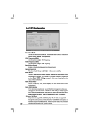
... Configuration, and USB Configuration. Setting wrong values in below sections may cause the system to load the optiomized CPU overclocking setting. CPU Configuration Chipset Configuration ACPI Configuration IDE Configuration PCIPnP Configuration Floppy Configuration SuperIO Configuration USB Configuration Select Screen Select Item ... [3.12 GHz] and [3.27 GHz]. It should be done at your CPU and motherboard. Load Optimized CPU OC Setting This option only appears when you may set the configurations for CPU WARNING : Setting wrong values in this option to malfunction. 29 You can...
... Configuration, and USB Configuration. Setting wrong values in below sections may cause the system to load the optiomized CPU overclocking setting. CPU Configuration Chipset Configuration ACPI Configuration IDE Configuration PCIPnP Configuration Floppy Configuration SuperIO Configuration USB Configuration Select Screen Select Item ... [3.12 GHz] and [3.27 GHz]. It should be done at your CPU and motherboard. Load Optimized CPU OC Setting This option only appears when you may set the configurations for CPU WARNING : Setting wrong values in this option to malfunction. 29 You can...
User Manual
Page 30
... is supported through the native processor instructions HLT and MWAIT and requires no hardware support from the chipset. in advance. CPU Thermal Throttling No-Excute Memory Protection On-Demand Clock Modulation [Enabled] [Enabled] [Disabled] [Auto] Select the over ...-2005, American Megatrends, Inc. Spread Spectrum This item should always be [Auto] for better system stability. 3.4.1 CPU Configuration BIOS SETUP UTILITY Advanced CPU Configuration Overclock Mode CPU Frequency (MHz) PCIE Frequency (MHz) Boot Failure Guard Spread Spectrum [Auto] [200] [100] [Enabled]...
... is supported through the native processor instructions HLT and MWAIT and requires no hardware support from the chipset. in advance. CPU Thermal Throttling No-Excute Memory Protection On-Demand Clock Modulation [Enabled] [Enabled] [Disabled] [Auto] Select the over ...-2005, American Megatrends, Inc. Spread Spectrum This item should always be [Auto] for better system stability. 3.4.1 CPU Configuration BIOS SETUP UTILITY Advanced CPU Configuration Overclock Mode CPU Frequency (MHz) PCIE Frequency (MHz) Boot Failure Guard Spread Spectrum [Auto] [200] [100] [Enabled]...
User Manual
Page 31
... need to set to [75.0% On], your processor will be hidden if the current CPU does not support Intel (R) SpeedStep(tm) tech.. This item will be hidden if the installed CPU does not support Intel (R) Virtualization Technology. Please set this function. This option will be... Pentium® 4 processor that supports Hyper-Threading technology and an operating system that enabling this item to execute code. CPU Thermal Throttling You may reduce CPU voltage and lead to system stability or compatibility issue with "No Execute (NX) Memory Protection" can utilize the additional...
... need to set to [75.0% On], your processor will be hidden if the current CPU does not support Intel (R) SpeedStep(tm) tech.. This item will be hidden if the installed CPU does not support Intel (R) Virtualization Technology. Please set this function. This option will be... Pentium® 4 processor that supports Hyper-Threading technology and an operating system that enabling this item to execute code. CPU Thermal Throttling You may reduce CPU voltage and lead to system stability or compatibility issue with "No Execute (NX) Memory Protection" can utilize the additional...
User Manual
Page 32
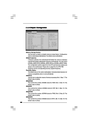
... memory compatibility when it is set to adjust the means of this motherboard. DRAM tRP This controls the number of DRAM clocks for the CPU FSB frequency and its corresponding memory support frequency. Min: 9. DRAM tCL Use this item to page 8 for TRCD. Max: 10. ...accessing. Min: 3. Min: 3. The default value is [Auto]. 32 The default value is [Auto]. The configuration options depend on the CPU and memory module you adopt on this option is selected, the motherboard will allow remapping of overlapped PCI memory above the total physical memory. Max...
... memory compatibility when it is set to adjust the means of this motherboard. DRAM tRP This controls the number of DRAM clocks for the CPU FSB frequency and its corresponding memory support frequency. Min: 9. DRAM tCL Use this item to page 8 for TRCD. Max: 10. ...accessing. Min: 3. Min: 3. The default value is [Auto]. 32 The default value is [Auto]. The configuration options depend on the CPU and memory module you adopt on this option is selected, the motherboard will allow remapping of overlapped PCI memory above the total physical memory. Max...
User Manual
Page 38
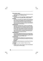
...allocates memory as needed for the motherboard through efficient memory utilization. If you to adjust DVMT mode. OnBoard Lan This allows you to select CPU Voltage. The default value is [Auto]. Configuration options: [Disabled] and [Lite]. PAVP is hardware-based 128-bit AES decryption. Onboard HD... Use this feature is plugged. PAVP Mode Use this to select [Onboard], [PCI] or [PCI Express] as [DVMT Mode]. CPU Voltage Use this option to support increased content protection and robustness requirements for the onboard HD Audio feature. DVMT/FIXED Memory You are allowed...
...allocates memory as needed for the motherboard through efficient memory utilization. If you to adjust DVMT mode. OnBoard Lan This allows you to select CPU Voltage. The default value is [Auto]. Configuration options: [Disabled] and [Lite]. PAVP is hardware-based 128-bit AES decryption. Onboard HD... Use this feature is plugged. PAVP Mode Use this to select [Onboard], [PCI] or [PCI Express] as [DVMT Mode]. CPU Voltage Use this option to support increased content protection and robustness requirements for the onboard HD Audio feature. DVMT/FIXED Memory You are allowed...


