User Manual
Page 5
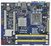
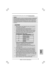
... ASRock G41C-VS motherboard, a reliable motherboard produced under ASRock's consistently stringent quality control. www.asrock.com/support/index.asp 1.1 Package Contents ASRock G41C-VS Motherboard (Micro ATX Form Factor: 8.8-in x 7.8-in, 22.4 cm x 19.8 cm) ASRock G41C-VS Quick Installation Guide ASRock G41C-VS Support CD Two Serial ATA (SATA) Data Cables (Optional) One I/O Panel Shield 5 You may find the latest VGA cards and CPU support lists on ASRock...
... ASRock G41C-VS motherboard, a reliable motherboard produced under ASRock's consistently stringent quality control. www.asrock.com/support/index.asp 1.1 Package Contents ASRock G41C-VS Motherboard (Micro ATX Form Factor: 8.8-in x 7.8-in, 22.4 cm x 19.8 cm) ASRock G41C-VS Quick Installation Guide ASRock G41C-VS Support CD Two Serial ATA (SATA) Data Cables (Optional) One I/O Panel Shield 5 You may find the latest VGA cards and CPU support lists on ASRock...

User Manual
Page 6
... x DDR2 DIMM slots - capacity of system memory: 8GB (see CAUTION 6) - Intel® Graphics Media Accelerator X4500 - Speed: 10/100 Ethernet - Supports Wake-On-LAN I /O - 1.2 Specifications Platform CPU Chipset Memory Expansion Slot Graphics Audio LAN Rear Panel I /O Panel - 1 x PS/2 Mouse Port - 1 x PS/2 Keyboard Port - 1 x Serial... 1) - Max. Micro ATX Form Factor: 8.8-in x 7.8-in, 22.4 cm x 19.8 cm - Supports EM64T CPU - Dual Channel DDR3/DDR2 Memory Technology (see CAUTION 4) - Supports DDR2 800/667/533 non-ECC, un-buffered memory (see CAUTION 3) - 2 x DDR3 DIMM slots -...
... x DDR2 DIMM slots - capacity of system memory: 8GB (see CAUTION 6) - Intel® Graphics Media Accelerator X4500 - Speed: 10/100 Ethernet - Supports Wake-On-LAN I /O - 1.2 Specifications Platform CPU Chipset Memory Expansion Slot Graphics Audio LAN Rear Panel I /O Panel - 1 x PS/2 Mouse Port - 1 x PS/2 Keyboard Port - 1 x Serial... 1) - Max. Micro ATX Form Factor: 8.8-in x 7.8-in, 22.4 cm x 19.8 cm - Supports EM64T CPU - Dual Channel DDR3/DDR2 Memory Technology (see CAUTION 4) - Supports DDR2 800/667/533 non-ECC, un-buffered memory (see CAUTION 3) - 2 x DDR3 DIMM slots -...
User Manual
Page 7
... Sensing - FCC, CE - EuP Ready (EuP ready power supply is required) (see CAUTION 9) - VCCM, NB, VTT, GTLRef Voltage Multi-adjustment - Supports Smart BIOS - ASRock OC Tuner (see CAUTION 15) 7 CPU Frequency Stepless Control (see CAUTION 8) - 8Mb AMI BIOS - Voltage Monitoring: +12V, +5V, +3.3V, Vcore - Microsoft® Windows® 7 / 7 64-bit / VistaTM / VistaTM 64...
... Sensing - FCC, CE - EuP Ready (EuP ready power supply is required) (see CAUTION 9) - VCCM, NB, VTT, GTLRef Voltage Multi-adjustment - Supports Smart BIOS - ASRock OC Tuner (see CAUTION 15) 7 CPU Frequency Stepless Control (see CAUTION 8) - 8Mb AMI BIOS - Voltage Monitoring: +12V, +5V, +3.3V, Vcore - Microsoft® Windows® 7 / 7 64-bit / VistaTM / VistaTM 64...

User Manual
Page 8
... the installation guide of "Hyper Threading Technology", please check page 34. 2. * For detailed product information, please visit our website: http://www.asrock.com WARNING Please realize that there is no such limitation. 6. Overclocking may be done at DDR3 533 if you adopt a DDR3 800 memory ... Technology, or using the thirdparty overclocking tools. Before you implement Dual Channel Memory Technology, make sure to adjust the jumper. CPU FSB Frequency Memory Support Frequency 1333 DDR3 800, DDR3 1066, DDR3 1333 DDR2 667, DDR2 800 1066 DDR3 800, DDR3 1066 DDR2 667, DDR2...
... the installation guide of "Hyper Threading Technology", please check page 34. 2. * For detailed product information, please visit our website: http://www.asrock.com WARNING Please realize that there is no such limitation. 6. Overclocking may be done at DDR3 533 if you adopt a DDR3 800 memory ... Technology, or using the thirdparty overclocking tools. Before you implement Dual Channel Memory Technology, make sure to adjust the jumper. CPU FSB Frequency Memory Support Frequency 1333 DDR3 800, DDR3 1066, DDR3 1333 DDR2 667, DDR2 800 1066 DDR3 800, DDR3 1066 DDR2 667, DDR2...

User Manual
Page 14
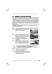
... the socket by using a purely vertical motion. Verify that the CPU is recommended to use the cap tab to handle and avoid kicking off the PnP cap. 2. This cap must be...mated to the orient keys. Step 4. Remove PnP Cap (Pick and Place Cap): Use your left hand index finger and thumb to support the load plate edge, engage PnP cap with right hand thumb and peel the cap from the socket while pressing on load plate,... engage the load lever. Step 2-4. For proper inserting, please ensure to match the two orientation key notches of the CPU with load plate tab under retention tab of load lever. 14
... the socket by using a purely vertical motion. Verify that the CPU is recommended to use the cap tab to handle and avoid kicking off the PnP cap. 2. This cap must be...mated to the orient keys. Step 4. Remove PnP Cap (Pick and Place Cap): Use your left hand index finger and thumb to support the load plate edge, engage PnP cap with right hand thumb and peel the cap from the socket while pressing on load plate,... engage the load lever. Step 2-4. For proper inserting, please ensure to match the two orientation key notches of the CPU with load plate tab under retention tab of load lever. 14
User Manual
Page 15
...to spray thermal interface material between the CPU and the heatsink to improve heat dissipation. Please adopt the type of heatsink and cooling fan compliant with the CPU fan connector on the motherboard. Ensure that supports Intel 775-LAND CPU. For proper installation, please kindly refer ...to the instruction manuals of your CPU fan and heatsink. Step 6. Apply thermal interface material onto ...
...to spray thermal interface material between the CPU and the heatsink to improve heat dissipation. Please adopt the type of heatsink and cooling fan compliant with the CPU fan connector on the motherboard. Ensure that supports Intel 775-LAND CPU. For proper installation, please kindly refer ...to the instruction manuals of your CPU fan and heatsink. Step 6. Apply thermal interface material onto ...
User Manual
Page 20
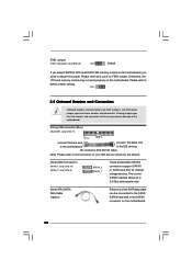
Serial ATAII Connectors (SATAII_1: see p.10, No. 10) (SATAII_2: see p.10, No. 9) SATAII_2 SATAII_1 These Serial ATAII (SATAII) connectors support SATAII or SATA hard disk for the details. FSB1 2.8 Onboard Headers and Connectors Onboard headers and connectors are NOT jumpers. Primary IDE connector (Blue) (39-... disk or the SATAII connector on this motherboard. Please short pin2, pin3 for FSB1 jumper. Placing jumper caps over these headers and connectors. Otherwise, the CPU and memory module may not work properly on this motherboard, you adopt FSB1333...
Serial ATAII Connectors (SATAII_1: see p.10, No. 10) (SATAII_2: see p.10, No. 9) SATAII_2 SATAII_1 These Serial ATAII (SATAII) connectors support SATAII or SATA hard disk for the details. FSB1 2.8 Onboard Headers and Connectors Onboard headers and connectors are NOT jumpers. Primary IDE connector (Blue) (39-... disk or the SATAII connector on this motherboard. Please short pin2, pin3 for FSB1 jumper. Placing jumper caps over these headers and connectors. Otherwise, the CPU and memory module may not work properly on this motherboard, you adopt FSB1333...

User Manual
Page 22
... GND FAN_SPEED_CONTROL 1 2 3 4 Please connect a CPU fan cable to this header. To activate the front mic. GND +12V CHA_FAN_SPEED Please connect a chassis fan cable to this motherboard provides 4-Pin CPU fan (Quiet Fan) support, the 3-Pin CPU fan still can work successfully even without the fan ...speed control function. CPU Fan Connector (4-pin CPU_FAN1) (see p.10 No. 17) PLED+ PLEDPWRBTN# GND ...
... GND FAN_SPEED_CONTROL 1 2 3 4 Please connect a CPU fan cable to this header. To activate the front mic. GND +12V CHA_FAN_SPEED Please connect a chassis fan cable to this motherboard provides 4-Pin CPU fan (Quiet Fan) support, the 3-Pin CPU fan still can work successfully even without the fan ...speed control function. CPU Fan Connector (4-pin CPU_FAN1) (see p.10 No. 17) PLED+ PLEDPWRBTN# GND ...

User Manual
Page 25
... drivers you enable Untied Overclocking function, please enter "Overclock Mode" option of your system can be auto-detected and listed on the support CD driver page. Please refer to the warning on this motherboard for the possible overclocking risk before you to your chassis. STEP 1:... Connect the SATA power cable to install those required drivers. Please follow the order from [Auto] to fixed PCI / PCIE buses. Therefore, CPU FSB is untied during overclocking, FSB enjoys better margin due to [Manual]. Then, the drivers compatible to install the SATA / SATAII hard disks...
... drivers you enable Untied Overclocking function, please enter "Overclock Mode" option of your system can be auto-detected and listed on the support CD driver page. Please refer to the warning on this motherboard for the possible overclocking risk before you to your chassis. STEP 1:... Connect the SATA power cable to install those required drivers. Please follow the order from [Auto] to fixed PCI / PCIE buses. Therefore, CPU FSB is untied during overclocking, FSB enjoys better margin due to [Manual]. Then, the drivers compatible to install the SATA / SATAII hard disks...
User Manual
Page 28
...Command Rate DRAM Timing Configuration [Auto] [Auto] If you can set MB before apply it. The configuration options depend on the CPU and memory module you adopt on this item to Sub Screen F1 General Help F9 Load Defaults F10 Save and Exit ESC Exit ... select [400MHz DDR3_800], [533MHz DDR3_1066] or [667MHz DDR3_1333] for DDR3 or [266MHz DDR2_533], [333MHz DDR2_667] or [400MHz DDR2_800] for the CPU FSB frequency and its corresponding memory support frequency. adjust jumper set up overclocking features. DRAM Command Rate Use this motherboard. Please refer to page 8 for DDR2.
...Command Rate DRAM Timing Configuration [Auto] [Auto] If you can set MB before apply it. The configuration options depend on the CPU and memory module you adopt on this item to Sub Screen F1 General Help F9 Load Defaults F10 Save and Exit ESC Exit ... select [400MHz DDR3_800], [533MHz DDR3_1066] or [667MHz DDR3_1333] for DDR3 or [266MHz DDR2_533], [333MHz DDR2_667] or [400MHz DDR2_800] for the CPU FSB frequency and its corresponding memory support frequency. adjust jumper set up overclocking features. DRAM Command Rate Use this motherboard. Please refer to page 8 for DDR2.

User Manual
Page 30
...for DDR2: [Auto], [1.80V] to [Disable] if above issue occurs. The default value of this motherboard is "Locked" or "Unlocked". If the CPU you adopt supports EIST (Intel (R) SpeedStep(tm) tech.), and you changing the ratio value of this motherboard. Configuration options: [Auto], [Enabled] and [Disabled]. Please ...If it shows "Unlocked", you will find this item appear to allow you plan to allow you will be hidden if the current CPU does not support Intel (R) SpeedStep(tm) tech.. Ratio CMOS Setting If the ratio status is [Auto]. The default value is unlocked, you changing...
...for DDR2: [Auto], [1.80V] to [Disable] if above issue occurs. The default value of this motherboard is "Locked" or "Unlocked". If the CPU you adopt supports EIST (Intel (R) SpeedStep(tm) tech.), and you changing the ratio value of this motherboard. Configuration options: [Auto], [Enabled] and [Disabled]. Please ...If it shows "Unlocked", you will find this item appear to allow you plan to allow you will be hidden if the current CPU does not support Intel (R) SpeedStep(tm) tech.. Ratio CMOS Setting If the ratio status is [Auto]. The default value is unlocked, you changing...

User Manual
Page 33
... Spectrum This item should always be [Auto] for better system stability. The C1 state is [Auto]. in advance. CPU Thermal Throttling No-Execute Memory Protection Intel (R) SpeedStep (tm) tech. If the CPU you adopt supports EIST (Intel (R) SpeedStep(tm) tech.), and you changing the ratio value of this motherboard. Ratio CMOS Setting If...
... Spectrum This item should always be [Auto] for better system stability. The C1 state is [Auto]. in advance. CPU Thermal Throttling No-Execute Memory Protection Intel (R) SpeedStep (tm) tech. If the CPU you adopt supports EIST (Intel (R) SpeedStep(tm) tech.), and you changing the ratio value of this motherboard. Ratio CMOS Setting If...

User Manual
Page 34
...if using Microsoft® Windows® XP, or Linux kernel version 2.4.18 or higher. This option will be hidden if the installed CPU does not support Hyper-Threading technology. Please note that includes optimization for this option to [Disable] if above issue occurs. Please set the "Power ...On] and [87.5% On]. Hyper Threading Technology To enable this item to [75.0% On], your processor will be hidden if the current CPU does not support Intel (R) SpeedStep(tm) tech.. If you need to set this feature, it requires a computer system with some power supplies. On-Demand ...
...if using Microsoft® Windows® XP, or Linux kernel version 2.4.18 or higher. This option will be hidden if the installed CPU does not support Hyper-Threading technology. Please note that includes optimization for this option to [Disable] if above issue occurs. Please set the "Power ...On] and [87.5% On]. Hyper Threading Technology To enable this item to [75.0% On], your processor will be hidden if the current CPU does not support Intel (R) SpeedStep(tm) tech.. If you need to set this feature, it requires a computer system with some power supplies. On-Demand ...
Quick Installation Guide
Page 4
...will be available on ASRock website as well. You may find the latest VGA cards and CPU support lists on ASRock website without notice. www.asrock.com/support/index.asp 1.1 Package Contents ASRock G41C-VS Motherboard (Micro ATX Form Factor: 8.8-in x 7.8-in the Support CD. Because the ...in the user manual presented in , 22.4 cm x 19.8 cm) ASRock G41C-VS Quick Installation Guide ASRock G41C-VS Support CD Two Serial ATA (SATA) Data Cables (Optional) One I/O Panel Shield 4 ASRock G41C-VS Motherboard English In case any modifications of the motherboard and step-bystep installation guide...
...will be available on ASRock website as well. You may find the latest VGA cards and CPU support lists on ASRock website without notice. www.asrock.com/support/index.asp 1.1 Package Contents ASRock G41C-VS Motherboard (Micro ATX Form Factor: 8.8-in x 7.8-in the Support CD. Because the ...in the user manual presented in , 22.4 cm x 19.8 cm) ASRock G41C-VS Quick Installation Guide ASRock G41C-VS Support CD Two Serial ATA (SATA) Data Cables (Optional) One I/O Panel Shield 4 ASRock G41C-VS Motherboard English In case any modifications of the motherboard and step-bystep installation guide...

Quick Installation Guide
Page 5
... CAUTION 5) - 1 x PCI Express x16 slot - 1 x PCI slot - Intel® Graphics Media Accelerator X4500 - resolution up to -Use USB 2.0 Ports 5 ASRock G41C-VS Motherboard English Dual Channel DDR3/DDR2 Memory Technology (see CAUTION 4) - Supports EM64T CPU - Supports DDR3 1333(OC)/1066/800 non-ECC, un-buffered memory (see CAUTION 3) - 2 x DDR3 DIMM slots - Pixel Shader 4.0, DirectX 10 - capacity...
... CAUTION 5) - 1 x PCI Express x16 slot - 1 x PCI slot - Intel® Graphics Media Accelerator X4500 - resolution up to -Use USB 2.0 Ports 5 ASRock G41C-VS Motherboard English Dual Channel DDR3/DDR2 Memory Technology (see CAUTION 4) - Supports EM64T CPU - Supports DDR3 1333(OC)/1066/800 non-ECC, un-buffered memory (see CAUTION 3) - 2 x DDR3 DIMM slots - Pixel Shader 4.0, DirectX 10 - capacity...
Quick Installation Guide
Page 6
... 15) 6 ASRock G41C-VS Motherboard Hybrid Booster: - CPU Quiet Fan - EuP Ready (EuP ready power supply is required) (see CAUTION 12) - VCCM, NB, VTT, GTLRef Voltage Multi-adjustment - ASRock Instant Flash (see CAUTION 7) - 1 x ATA100 IDE connector (supports 2 x IDE devices) - 1 x Print port header - HD Audio Jack: Line in / Front Speaker / Microphone Connector - 2 x SATAII 3.0 Gb/s connectors (No Support for...
... 15) 6 ASRock G41C-VS Motherboard Hybrid Booster: - CPU Quiet Fan - EuP Ready (EuP ready power supply is required) (see CAUTION 12) - VCCM, NB, VTT, GTLRef Voltage Multi-adjustment - ASRock Instant Flash (see CAUTION 7) - 1 x ATA100 IDE connector (supports 2 x IDE devices) - 1 x Print port header - HD Audio Jack: Line in / Front Speaker / Microphone Connector - 2 x SATAII 3.0 Gb/s connectors (No Support for...
Quick Installation Guide
Page 7
...Setup Guide" on page 12 for details. 3. You can also connect SATA hard disk to adjust the jumper. This motherboard supports Dual Channel Memory Technology. Please check the table below for proper jumper settings. 5. The maximum shared memory size is defined ...FSB1333-CPU and DDR3 1333 memory module on this motherboard, you need to SATAII connector directly. 8. It should be less than 4GB for the reservation for the latest information. 7. We are not responsible for USB 2.0 works fine under Windows® 7 / VistaTM / XP. English 7 ASRock G41C-VS ...
...Setup Guide" on page 12 for details. 3. You can also connect SATA hard disk to adjust the jumper. This motherboard supports Dual Channel Memory Technology. Please check the table below for proper jumper settings. 5. The maximum shared memory size is defined ...FSB1333-CPU and DDR3 1333 memory module on this motherboard, you need to SATAII connector directly. 8. It should be less than 4GB for the reservation for the latest information. 7. We are not responsible for USB 2.0 works fine under Windows® 7 / VistaTM / XP. English 7 ASRock G41C-VS ...
Quick Installation Guide
Page 10
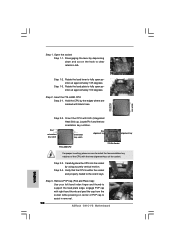
... 1-3. Pin1 orientation key notch orientation key notch Pin1 alignment key alignment key 775-LAND CPU 775-Pin Socket For proper inserting, please ensure to assist in removal. 10 ASRock G41C-VS Motherboard Step 1-2. Orient the CPU with the two alignment keys of PnP cap to match the two orientation key notches of...Sink) up. Open the socket: Step 1-1. Step 1. Step 2. Hold the CPU by the edges where are marked with right hand thumb and peel the cap from the socket while pressing on the hook to support the load plate edge, engage PnP cap with black lines. Remove PnP Cap (...
... 1-3. Pin1 orientation key notch orientation key notch Pin1 alignment key alignment key 775-LAND CPU 775-Pin Socket For proper inserting, please ensure to assist in removal. 10 ASRock G41C-VS Motherboard Step 1-2. Orient the CPU with the two alignment keys of PnP cap to match the two orientation key notches of...Sink) up. Open the socket: Step 1-1. Step 1. Step 2. Hold the CPU by the edges where are marked with right hand thumb and peel the cap from the socket while pressing on the hook to support the load plate edge, engage PnP cap with black lines. Remove PnP Cap (...

Quick Installation Guide
Page 16
...storage devices. Primary IDE connector (Blue) (39-pin IDE1, see p.2, No. 9) SATAII_2 SATAII_1 These Serial ATAII (SATAII) connectors support SATAII or SATA hard disk for FSB1 jumper. FSB1 Jumper (FSB1, 3-pin jumper, see p.2 No. 20) Default If you ...CPU and DDR3 1333 memory module on the motherboard. Please refer to 3.0 Gb/s data transfer rate. Placing jumper caps over these headers and connectors. The current SATAII interface allows up to below jumper setting. 2.6 Onboard Headers and Connectors Onboard headers and connectors are NOT jumpers. English 16 ASRock G41C-VS...
...storage devices. Primary IDE connector (Blue) (39-pin IDE1, see p.2, No. 9) SATAII_2 SATAII_1 These Serial ATAII (SATAII) connectors support SATAII or SATA hard disk for FSB1 jumper. FSB1 Jumper (FSB1, 3-pin jumper, see p.2 No. 20) Default If you ...CPU and DDR3 1333 memory module on the motherboard. Please refer to 3.0 Gb/s data transfer rate. Placing jumper caps over these headers and connectors. The current SATAII interface allows up to below jumper setting. 2.6 Onboard Headers and Connectors Onboard headers and connectors are NOT jumpers. English 16 ASRock G41C-VS...

Quick Installation Guide
Page 18
...(3-pin CHA_FAN1) (see p.2 No. 13) Please connect the chassis speaker to the ground pin. Pin 1-3 Connected 3-Pin Fan Installation 18 ASRock G41C-VS Motherboard G. CPU Fan Connector (4-pin CPU_FAN1) (see p.2 No. 12) This header accommodates several system front panel functions. If you want to the "Front... the change by clicking "OK". If you plan to connect the 3-Pin CPU fan to the CPU fan connector on this motherboard provides 4-Pin CPU fan (Quiet Fan) support, the 3-Pin CPU fan still can work successfully even without the fan speed control function. Click ...
...(3-pin CHA_FAN1) (see p.2 No. 13) Please connect the chassis speaker to the ground pin. Pin 1-3 Connected 3-Pin Fan Installation 18 ASRock G41C-VS Motherboard G. CPU Fan Connector (4-pin CPU_FAN1) (see p.2 No. 12) This header accommodates several system front panel functions. If you want to the "Front... the change by clicking "OK". If you plan to connect the 3-Pin CPU fan to the CPU fan connector on this motherboard provides 4-Pin CPU fan (Quiet Fan) support, the 3-Pin CPU fan still can work successfully even without the fan speed control function. Click ...


