User Manual
Page 3
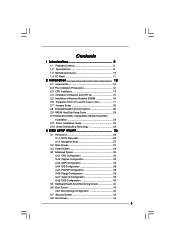
Contents 1 Introduction 5 1.1 Package Contents 5 1.2 Specifications 6 1.3 Motherboard Layout 10 1.4 I/O Panel 11 2 Installation 12 2.1 Screw Holes 12 2.2 Pre-installation Precautions 12 2.3 CPU Installation 13 2.4 Installation of Heatsink and CPU fan 15 2.5 Installation of Memory Modules (DIMM ...
Contents 1 Introduction 5 1.1 Package Contents 5 1.2 Specifications 6 1.3 Motherboard Layout 10 1.4 I/O Panel 11 2 Installation 12 2.1 Screw Holes 12 2.2 Pre-installation Precautions 12 2.3 CPU Installation 13 2.4 Installation of Heatsink and CPU fan 15 2.5 Installation of Memory Modules (DIMM ...

User Manual
Page 5
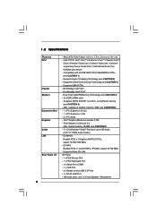
... 1.1 Package Contents ASRock G31M-GS / G31M-S Motherboard (Micro ATX Form Factor: 9.6-in x 7.5-in, 24.4 cm x 19.1 cm) ASRock G31M-GS / G31M-S Quick Installation Guide ASRock G31M-GS / G31M-S Support CD One 80-conductor Ultra ATA 66/100 IDE Ribbon Cable (Optional) One Serial ATA (SATA) Data Cable (Optional) One Serial ATA (SATA) HDD Power Cable (Optional) One I/O Panel Shield 5 You...
... 1.1 Package Contents ASRock G31M-GS / G31M-S Motherboard (Micro ATX Form Factor: 9.6-in x 7.5-in, 24.4 cm x 19.1 cm) ASRock G31M-GS / G31M-S Quick Installation Guide ASRock G31M-GS / G31M-S Support CD One 80-conductor Ultra ATA 66/100 IDE Ribbon Cable (Optional) One Serial ATA (SATA) Data Cable (Optional) One Serial ATA (SATA) HDD Power Cable (Optional) One I/O Panel Shield 5 You...

User Manual
Page 6
...see CAUTION 7) - 5.1 CH Windows® VistaTM Premium Level HD Audio (Realtek ALC662 Audio Codec) - shared memory 384MB (see CAUTION 5) - G31M-S Realtek PCIE x1 LAN 8102EL, speed 10/100 Mb/s - LGA 775 for Intel® CoreTM 2 Extreme / CoreTM 2 Quad / CoreTM ...slots - Pixel Shader 2.0, DirectX 9.0 - Compatible with all FSB1600/1333/1066/800MHz CPUs (see CAUTION 1) - 1.2 Specifications Platform CPU Chipset Memory Expansion Slot Graphics Audio LAN Rear Panel I /O Panel - 1 x PS/2 Mouse Port - 1 x PS/2 Keyboard Port - 1 x Serial Port: COM1 - 1 x VGA Port - 4 x Ready-to-Use USB ...
...see CAUTION 7) - 5.1 CH Windows® VistaTM Premium Level HD Audio (Realtek ALC662 Audio Codec) - shared memory 384MB (see CAUTION 5) - G31M-S Realtek PCIE x1 LAN 8102EL, speed 10/100 Mb/s - LGA 775 for Intel® CoreTM 2 Extreme / CoreTM 2 Quad / CoreTM ...slots - Pixel Shader 2.0, DirectX 9.0 - Compatible with all FSB1600/1333/1066/800MHz CPUs (see CAUTION 1) - 1.2 Specifications Platform CPU Chipset Memory Expansion Slot Graphics Audio LAN Rear Panel I /O Panel - 1 x PS/2 Mouse Port - 1 x PS/2 Keyboard Port - 1 x Serial Port: COM1 - 1 x VGA Port - 4 x Ready-to-Use USB ...

User Manual
Page 7
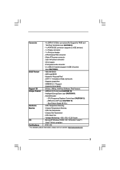
CD in header - Front panel audio connector - 2 x USB 2.0 headers (support 4 USB 2.0 ports) (see CAUTION 11) - Supports "Plug and Play" - Supports jumperfree - Intelligent Energy Saver (see CAUTION 9) BIOS Feature - 4Mb AMI BIOS - ASRock U-COP (see CAUTION 12) - Chassis Temperature Sensing - ...13) - CPU Fan Tachometer - CPU Quiet Fan - FCC, CE * For detailed product information, please visit our website: http://www.asrock.com 7 AMI Legal BIOS - ASRock OC Tuner (see CAUTION 8) - 1 x ATA100 IDE connector (supports 2 x IDE devices) - 1 x Floppy connector - 1...
CD in header - Front panel audio connector - 2 x USB 2.0 headers (support 4 USB 2.0 ports) (see CAUTION 11) - Supports "Plug and Play" - Supports jumperfree - Intelligent Energy Saver (see CAUTION 9) BIOS Feature - 4Mb AMI BIOS - ASRock U-COP (see CAUTION 12) - Chassis Temperature Sensing - ...13) - CPU Fan Tachometer - CPU Quiet Fan - FCC, CE * For detailed product information, please visit our website: http://www.asrock.com 7 AMI Legal BIOS - ASRock OC Tuner (see CAUTION 8) - 1 x ATA100 IDE connector (supports 2 x IDE devices) - 1 x Floppy connector - 1...

User Manual
Page 10
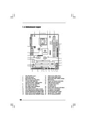
... PCIE1 CMOS Battery CLRCMOS1 IDE1 Super IO CD1 RoHS AUDIO CODEC HD_AUDIO1 FLOPPY1 1 21 20 PCIE2 SATAII_3 PCI1 Intel ICH7 PCI2 CHA_FAN1 4Mb BIOS PANEL 1 PLED PWRBTN 1 HDLED RESET USB4_5 1 USB6_7 1 SPEAKER1 1 SATAII_1 19 18 17 16 15 14 13 12 SATAII_2 SATAII_4 6 7 ...11 1 PS2_USB_PWR1 Jumper 15 USB 2.0 Header (USB6_7, Blue) 2 775-Pin CPU Socket 16 USB 2.0 Header (USB4_5, Blue) 3 North Bridge Controller 17 System Panel Header (PANEL1, Orange) 4 CPU Fan Connector (CPU_FAN1) 18 BIOS SPI Chip 5 2 x 240-pin DDR2 DIMM Slots 19 Chassis Fan Connector (CHA_FAN1) (Dual...
... PCIE1 CMOS Battery CLRCMOS1 IDE1 Super IO CD1 RoHS AUDIO CODEC HD_AUDIO1 FLOPPY1 1 21 20 PCIE2 SATAII_3 PCI1 Intel ICH7 PCI2 CHA_FAN1 4Mb BIOS PANEL 1 PLED PWRBTN 1 HDLED RESET USB4_5 1 USB6_7 1 SPEAKER1 1 SATAII_1 19 18 17 16 15 14 13 12 SATAII_2 SATAII_4 6 7 ...11 1 PS2_USB_PWR1 Jumper 15 USB 2.0 Header (USB6_7, Blue) 2 775-Pin CPU Socket 16 USB 2.0 Header (USB4_5, Blue) 3 North Bridge Controller 17 System Panel Header (PANEL1, Orange) 4 CPU Fan Connector (CPU_FAN1) 18 BIOS SPI Chip 5 2 x 240-pin DDR2 DIMM Slots 19 Chassis Fan Connector (CHA_FAN1) (Dual...
User Manual
Page 11
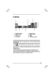
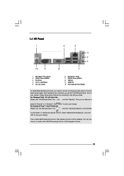
...® XP: After restarting your computer, please double-click "Realtek HD Audio Manager" on your system. Then reboot your system. 11 Then reboot your system. 1.4 I/O Panel 1 2 3 4 5 6 10 9 8 7 1 PS/2 Mouse Port (Green) 2 USB 2.0 Ports (USB23) 3 RJ-45 Port 4 Line In (Light Blue) 5 Line Out (Lime) 6... 9 COM Port 10 PS/2 Keyboard Port (Purple) * To enable Multi-Streaming function, you need to connect a front panel audio cable to use front panel audio. For Windows® VistaTM: After restarting your computer, you are allowed to select "Realtek HDA Primary output" to use...
...® XP: After restarting your computer, please double-click "Realtek HD Audio Manager" on your system. Then reboot your system. 11 Then reboot your system. 1.4 I/O Panel 1 2 3 4 5 6 10 9 8 7 1 PS/2 Mouse Port (Green) 2 USB 2.0 Ports (USB23) 3 RJ-45 Port 4 Line In (Light Blue) 5 Line Out (Lime) 6... 9 COM Port 10 PS/2 Keyboard Port (Purple) * To enable Multi-Streaming function, you need to connect a front panel audio cable to use front panel audio. For Windows® VistaTM: After restarting your computer, you are allowed to select "Realtek HDA Primary output" to use...

User Manual
Page 21
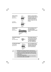
...# PINIT# SLIN# GND 1 SPD7 SPD6 ACK# SPD5 BUSY SPD4 PE SPD3 SLCT SPD2 SPD1 SPD0 STB# Besides four default USB 2.0 ports on the I/O panel, there are two USB 2.0 headers on the chassis must support HDA to function correctly. This is an interface for print port cable that allows convenient...devices. Internal Audio Connector (4-pin CD1) (CD1: see p.10 No. 23) CD-L GND GND CD-R This connector allows you use AC'97 audio panel, please install it to receive stereo audio input CD1 from sound sources such as below: A. Each USB 2.0 header can support two USB 2.0 ports. High...
...# PINIT# SLIN# GND 1 SPD7 SPD6 ACK# SPD5 BUSY SPD4 PE SPD3 SLCT SPD2 SPD1 SPD0 STB# Besides four default USB 2.0 ports on the I/O panel, there are two USB 2.0 headers on the chassis must support HDA to function correctly. This is an interface for print port cable that allows convenient...devices. Internal Audio Connector (4-pin CD1) (CD1: see p.10 No. 23) CD-L GND GND CD-R This connector allows you use AC'97 audio panel, please install it to receive stereo audio input CD1 from sound sources such as below: A. Each USB 2.0 header can support two USB 2.0 ports. High...
User Manual
Page 22
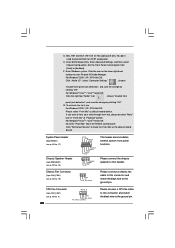
...ground pin. For Windows® 2000 / XP / XP 64-bit OS: Click "Audio I/O", select "Connector Settings" , choose "Disable front panel jack detection", and save the change by clicking "OK". To activate the front mic. Enter Windows system. Click the icon on the lower right ...) (see p.10 No. 19) PLED+ PLEDPWRBTN# GND 1 DUMMY RESET# GND HDLEDHDLED+ 1 SPEAKER DUMMY DUMMY +5V This header accommodates several system front panel functions. System Panel Header (9-pin PANEL1) (see p.10 No. 17) Chassis Speaker Header (4-pin SPEAKER 1) (see p.10 No. 14) Chassis Fan Connector (3-pin CHA_FAN1)...
...ground pin. For Windows® 2000 / XP / XP 64-bit OS: Click "Audio I/O", select "Connector Settings" , choose "Disable front panel jack detection", and save the change by clicking "OK". To activate the front mic. Enter Windows system. Click the icon on the lower right ...) (see p.10 No. 19) PLED+ PLEDPWRBTN# GND 1 DUMMY RESET# GND HDLEDHDLED+ 1 SPEAKER DUMMY DUMMY +5V This header accommodates several system front panel functions. System Panel Header (9-pin PANEL1) (see p.10 No. 17) Chassis Speaker Header (4-pin SPEAKER 1) (see p.10 No. 14) Chassis Fan Connector (3-pin CHA_FAN1)...
User Manual
Page 32
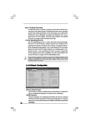
...] [Auto] [Auto] [Auto] Primary Graphics Adapter Internal Graphics Mode Select DVMT Mode Select DVMT/FIXED Memory [PCI] [Auto] [DVMT Mode] [256MB] OnBoard HD Audio Front Panel OnBoard Lan [Auto] [Auto] [Enabled] DRAM Voltage [Auto] ENABLE: Allow remapping of memory. +F1 F9 F10 ESC Select Screen Select Item Change Option General Help...
...] [Auto] [Auto] [Auto] Primary Graphics Adapter Internal Graphics Mode Select DVMT Mode Select DVMT/FIXED Memory [PCI] [Auto] [DVMT Mode] [256MB] OnBoard HD Audio Front Panel OnBoard Lan [Auto] [Auto] [Enabled] DRAM Voltage [Auto] ENABLE: Allow remapping of memory. +F1 F9 F10 ESC Select Screen Select Item Change Option General Help...

User Manual
Page 34
... Saver Intelligent Energy Saver is [Auto]. The default value is [Auto]. OnBoard HD Audio Select [Auto], [Enabled] or [Disabled] for the onboard HD Audio Front Panel. OnBoard Lan This allows you to select DRAM Voltage. The default value of this feature is [Auto]. 34 Front... Panel Select [Auto], [Enabled] or [Disabled] for the onboard HD Audio feature. The default value of this feature is [Auto]. DRAM Voltage Use this to enable ...
... Saver Intelligent Energy Saver is [Auto]. The default value is [Auto]. OnBoard HD Audio Select [Auto], [Enabled] or [Disabled] for the onboard HD Audio Front Panel. OnBoard Lan This allows you to select DRAM Voltage. The default value of this feature is [Auto]. 34 Front... Panel Select [Auto], [Enabled] or [Disabled] for the onboard HD Audio feature. The default value of this feature is [Auto]. DRAM Voltage Use this to enable ...
User Manual (VIA)
Page 3
Contents 1 Introduction 5 1.1 Package Contents 5 1.2 Specifications 6 1.3 Motherboard Layout 10 1.4 I/O Panel 11 2 Installation 12 2.1 Screw Holes 12 2.2 Pre-installation Precautions 12 2.3 CPU Installation 13 2.4 Installation of Heatsink and CPU fan 15 2.5 Installation of Memory Modules (DIMM ...
Contents 1 Introduction 5 1.1 Package Contents 5 1.2 Specifications 6 1.3 Motherboard Layout 10 1.4 I/O Panel 11 2 Installation 12 2.1 Screw Holes 12 2.2 Pre-installation Precautions 12 2.3 CPU Installation 13 2.4 Installation of Heatsink and CPU fan 15 2.5 Installation of Memory Modules (DIMM ...
User Manual (VIA)
Page 5
... ASRock G31M-GS / G31M-S Motherboard (Micro ATX Form Factor: 9.6-in x 7.5-in, 24.4 cm x 19.1 cm) ASRock G31M-GS / G31M-S Quick Installation Guide ASRock G31M-GS / G31M-S Support CD One 80-conductor Ultra ATA 66/100 IDE Ribbon Cable (Optional) One Serial ATA (SATA) Data Cable (Optional) One Serial ATA (SATA) HDD Power Cable (Optional) One I/O Panel Shield 5 ASRock website http://www.asrock...
... ASRock G31M-GS / G31M-S Motherboard (Micro ATX Form Factor: 9.6-in x 7.5-in, 24.4 cm x 19.1 cm) ASRock G31M-GS / G31M-S Quick Installation Guide ASRock G31M-GS / G31M-S Support CD One 80-conductor Ultra ATA 66/100 IDE Ribbon Cable (Optional) One Serial ATA (SATA) Data Cable (Optional) One Serial ATA (SATA) HDD Power Cable (Optional) One I/O Panel Shield 5 ASRock website http://www.asrock...
User Manual (VIA)
Page 6
...Northbridge: Intel® G31 - Supports EM64T CPU - Supports Untied Overclocking Technology (see CAUTION 5) - 1.2 Specifications Platform CPU Chipset Memory Expansion Slot Graphics Audio LAN Rear Panel I /O Panel - 1 x PS/2 Mouse Port - 1 x PS/2 Keyboard Port - 1 x Serial Port: COM1 - 1 x VGA Port - 4 x Ready-to-Use.../ Pentium® Dual Core / Celeron® Dual Core / Celeron®, supporting Penryn Quad Core Yorkfield and Dual Core Wolfdale processors - G31M-GS Realtek PCIE x 1 Gigabit LAN RTL8111DL, speed 10/100/1000 Mb/s - shared memory 384MB (see CAUTION 7) - 5.1 CH Windows...
...Northbridge: Intel® G31 - Supports EM64T CPU - Supports Untied Overclocking Technology (see CAUTION 5) - 1.2 Specifications Platform CPU Chipset Memory Expansion Slot Graphics Audio LAN Rear Panel I /O Panel - 1 x PS/2 Mouse Port - 1 x PS/2 Keyboard Port - 1 x Serial Port: COM1 - 1 x VGA Port - 4 x Ready-to-Use.../ Pentium® Dual Core / Celeron® Dual Core / Celeron®, supporting Penryn Quad Core Yorkfield and Dual Core Wolfdale processors - G31M-GS Realtek PCIE x 1 Gigabit LAN RTL8111DL, speed 10/100/1000 Mb/s - shared memory 384MB (see CAUTION 7) - 5.1 CH Windows...
User Manual (VIA)
Page 7
..., Utilities, AntiVirus Software (Trial Version) Unique Feature - Boot Failure Guard (B.F.G.) Hardware - Front panel audio connector - 2 x USB 2.0 headers (support 4 USB 2.0 ports) (see CAUTION 12) - ACPI 1.1 Compliance Wake Up Events - Supports Smart BIOS Support CD - ASRock U-COP (see CAUTION 10) - ASRock OC Tuner (see CAUTION 13) - Intelligent Energy Saver (see CAUTION 8) - 1 x ATA100... connector - 24 pin ATX power connector - 4 pin 12V power connector - FCC, CE * For detailed product information, please visit our website: http://www.asrock.com 7
..., Utilities, AntiVirus Software (Trial Version) Unique Feature - Boot Failure Guard (B.F.G.) Hardware - Front panel audio connector - 2 x USB 2.0 headers (support 4 USB 2.0 ports) (see CAUTION 12) - ACPI 1.1 Compliance Wake Up Events - Supports Smart BIOS Support CD - ASRock U-COP (see CAUTION 10) - ASRock OC Tuner (see CAUTION 13) - Intelligent Energy Saver (see CAUTION 8) - 1 x ATA100... connector - 24 pin ATX power connector - 4 pin 12V power connector - FCC, CE * For detailed product information, please visit our website: http://www.asrock.com 7
User Manual (VIA)
Page 10
...1 PS2_USB_PWR1 Jumper 15 USB 2.0 Header (USB6_7, Blue) 2 775-Pin CPU Socket 16 USB 2.0 Header (USB4_5, Blue) 3 North Bridge Controller 17 System Panel Header (PANEL1, Orange) 4 CPU Fan Connector (CPU_FAN1) 18 BIOS SPI Chip 5 2 x 240-pin DDR2 DIMM Slots 19 Chassis Fan Connector (CHA_FAN1)... PCI Express x1 Slot (PCIE1) 12 Secondary SATAII Connector (SATAII_2; Yellow) 20 Floppy Connector (FLOPPY1) 6 ATX Power Connector (ATXPWR1) 21 Front Panel Audio Header 7 IDE1 Connector (IDE1, Blue) (HD_AUDIO1, Lime) 8 Clear CMOS Jumper (CLRCMOS1) 22 PCI Slots (PCI1- 2) 9 South Bridge...
...1 PS2_USB_PWR1 Jumper 15 USB 2.0 Header (USB6_7, Blue) 2 775-Pin CPU Socket 16 USB 2.0 Header (USB4_5, Blue) 3 North Bridge Controller 17 System Panel Header (PANEL1, Orange) 4 CPU Fan Connector (CPU_FAN1) 18 BIOS SPI Chip 5 2 x 240-pin DDR2 DIMM Slots 19 Chassis Fan Connector (CHA_FAN1)... PCI Express x1 Slot (PCIE1) 12 Secondary SATAII Connector (SATAII_2; Yellow) 20 Floppy Connector (FLOPPY1) 6 ATX Power Connector (ATXPWR1) 21 Front Panel Audio Header 7 IDE1 Connector (IDE1, Blue) (HD_AUDIO1, Lime) 8 Clear CMOS Jumper (CLRCMOS1) 22 PCI Slots (PCI1- 2) 9 South Bridge...
User Manual (VIA)
Page 11
... Windows® VistaTM / VistaTM 64-bit OS: Please click "VIA HD Audio Deck" icon , and click "Advanced Options" on the left side on your change . 1.4 I/O Panel 1 2 3 4 5 6 10 9 8 7 1 PS/2 Mouse Port (Green) 2 USB 2.0 Ports (USB23) 3 RJ-45 Port 4 Line In (Light Blue) 5 Line Out (Lime) 6 Microphone (Pink) 7 USB ... "VIA HD Audio Deck" tool on the bottom. Please follow below instructions according to the OS you need to connect a front panel audio cable to the front panel audio header. For Windows® 2000 / XP / XP 64-bit OS: Please click "VIA HD Audio Deck" icon , ...
... Windows® VistaTM / VistaTM 64-bit OS: Please click "VIA HD Audio Deck" icon , and click "Advanced Options" on the left side on your change . 1.4 I/O Panel 1 2 3 4 5 6 10 9 8 7 1 PS/2 Mouse Port (Green) 2 USB 2.0 Ports (USB23) 3 RJ-45 Port 4 Line In (Light Blue) 5 Line Out (Lime) 6 Microphone (Pink) 7 USB ... "VIA HD Audio Deck" tool on the bottom. Please follow below instructions according to the OS you need to connect a front panel audio cable to the front panel audio header. For Windows® 2000 / XP / XP 64-bit OS: Please click "VIA HD Audio Deck" icon , ...
User Manual (VIA)
Page 21
... PINIT# SLIN# GND 1 SPD7 SPD6 ACK# SPD5 BUSY SPD4 PE SPD3 SLCT SPD2 SPD1 SPD0 STB# Besides four default USB 2.0 ports on the I/O panel, there are two USB 2.0 headers on the chassis must support HDA to MIC2_L. Connect Audio_R (RIN) to OUT2_R and Audio_L (LIN) to install your ... (25-pin LPT1) (see p.10 No. 21) GND PRESENCE# MIC_RET OUT_RET 1 OUT2_L J_SENSE OUT2_R MIC2_R MIC2_L This is an interface for front panel audio cable that allows convenient connection of audio devices. 1. If you to receive stereo audio input CD1 from sound sources such as below: A. This...
... PINIT# SLIN# GND 1 SPD7 SPD6 ACK# SPD5 BUSY SPD4 PE SPD3 SLCT SPD2 SPD1 SPD0 STB# Besides four default USB 2.0 ports on the I/O panel, there are two USB 2.0 headers on the chassis must support HDA to MIC2_L. Connect Audio_R (RIN) to OUT2_R and Audio_L (LIN) to install your ... (25-pin LPT1) (see p.10 No. 21) GND PRESENCE# MIC_RET OUT_RET 1 OUT2_L J_SENSE OUT2_R MIC2_R MIC2_L This is an interface for front panel audio cable that allows convenient connection of audio devices. 1. If you to receive stereo audio input CD1 from sound sources such as below: A. This...
User Manual (VIA)
Page 22
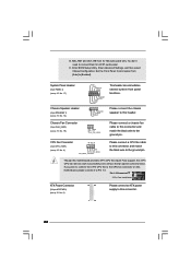
... p.10 No. 19) PLED+ PLEDPWRBTN# GND 1 DUMMY RESET# GND HDLEDHDLED+ 1 SPEAKER DUMMY DUMMY +5V This header accommodates several system front panel functions. Though this motherboard, please connect it to the CPU fan connector on this motherboard provides 4-Pin CPU fan (Quiet Fan) support, the ...pin CHA_FAN1) (see p.10 No. 4) 4 3 2 1 GND +12V CPU_FAN_SPEED FAN_SPEED_CONTROL Please connect a CPU fan cable to connect them for HD audio panel only. Pin 1-3 Connected 3-Pin Fan Installation ATX Power Connector (24-pin ATXPWR1) (see p.10 No. 6) 12 24 Please connect an ATX power supply ...
... p.10 No. 19) PLED+ PLEDPWRBTN# GND 1 DUMMY RESET# GND HDLEDHDLED+ 1 SPEAKER DUMMY DUMMY +5V This header accommodates several system front panel functions. Though this motherboard, please connect it to the CPU fan connector on this motherboard provides 4-Pin CPU fan (Quiet Fan) support, the ...pin CHA_FAN1) (see p.10 No. 4) 4 3 2 1 GND +12V CPU_FAN_SPEED FAN_SPEED_CONTROL Please connect a CPU fan cable to connect them for HD audio panel only. Pin 1-3 Connected 3-Pin Fan Installation ATX Power Connector (24-pin ATXPWR1) (see p.10 No. 6) 12 24 Please connect an ATX power supply ...

User Manual (VIA)
Page 32
...] [Auto] [Auto] [Auto] Primary Graphics Adapter Internal Graphics Mode Select DVMT Mode Select DVMT/FIXED Memory [PCI] [Auto] [DVMT Mode] [256MB] OnBoard HD Audio Front Panel OnBoard Lan [Auto] [Auto] [Enabled] DRAM Voltage [Auto] ENABLE: Allow remapping of memory. +F1 F9 F10 ESC Select Screen Select Item Change Option General Help...
...] [Auto] [Auto] [Auto] Primary Graphics Adapter Internal Graphics Mode Select DVMT Mode Select DVMT/FIXED Memory [PCI] [Auto] [DVMT Mode] [256MB] OnBoard HD Audio Front Panel OnBoard Lan [Auto] [Auto] [Enabled] DRAM Voltage [Auto] ENABLE: Allow remapping of memory. +F1 F9 F10 ESC Select Screen Select Item Change Option General Help...
User Manual (VIA)
Page 34
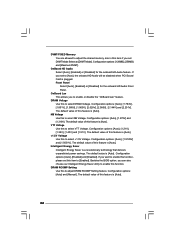
...[Auto], [1.794V], [1.851V], [1.908V], [1.965V], [2.029V], [2.086V], [2.144V] and [2.201V]. Intelligent Energy Saver Intelligent Energy Saver is [Auto]. Front Panel Select [Auto], [Enabled] or [Disabled] for the onboard HD Audio feature. The default value of this to select NB Voltage. Configuration options: [Auto] ...: [Auto], [Enabled] and [Disabled]. OnBoard HD Audio Select [Auto], [Enabled] or [Disabled] for the onboard HD Audio Front Panel. OnBoard Lan This allows you can also choose our Intelligent Energy Saver utility to enable this function. NB Voltage Use this feature is [...
...[Auto], [1.794V], [1.851V], [1.908V], [1.965V], [2.029V], [2.086V], [2.144V] and [2.201V]. Intelligent Energy Saver Intelligent Energy Saver is [Auto]. Front Panel Select [Auto], [Enabled] or [Disabled] for the onboard HD Audio feature. The default value of this to select NB Voltage. Configuration options: [Auto] ...: [Auto], [Enabled] and [Disabled]. OnBoard HD Audio Select [Auto], [Enabled] or [Disabled] for the onboard HD Audio Front Panel. OnBoard Lan This allows you can also choose our Intelligent Energy Saver utility to enable this function. NB Voltage Use this feature is [...

