
User Manual
Page 3
Contents 1 Introduction 5 1.1 Package Contents 5 1.2 Specifications 6 1.3 Motherboard Layout 10 1.4 I/O Panel (G31M-GS 11 1.5 I/O Panel (G31M-S 12 2 Installation 13 2.1 Screw Holes 13 2.2 Pre-installation Precautions 13 2.3 CPU Installation 14 2.4 Installation of Heatsink and CPU fan 16 2.5 Installation of Memory Modules (DIMM 17 2.6 Expansion Slots (PCI and PCI Express Slots 18 2.7 Jumpers Setup 19 2.8 Onboard Headers and Connectors 21...
Contents 1 Introduction 5 1.1 Package Contents 5 1.2 Specifications 6 1.3 Motherboard Layout 10 1.4 I/O Panel (G31M-GS 11 1.5 I/O Panel (G31M-S 12 2 Installation 13 2.1 Screw Holes 13 2.2 Pre-installation Precautions 13 2.3 CPU Installation 14 2.4 Installation of Heatsink and CPU fan 16 2.5 Installation of Memory Modules (DIMM 17 2.6 Expansion Slots (PCI and PCI Express Slots 18 2.7 Jumpers Setup 19 2.8 Onboard Headers and Connectors 21...
User Manual
Page 6
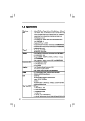
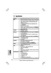
... Realtek PCIE x 1 Gigabit LAN RTL8111DL, speed 10/100/1000 Mb/s - G31M-S Realtek PCIE x1 LAN 8103EL / 8102EL, speed 10/100 Mb/s - Micro ATX Form Factor: 9.6-in x 7.2-in, 24.4 cm x 18.3 cm - Supports Untied Overclocking Technology (see ... CAUTION 5) - Southbridge: Intel® ICH7 - Supports Wake-On-LAN I /O 6 - Compatible with LED (ACT/LINK LED and SPEED LED) Dual Channel DDR2 Memory Technology (see CAUTION 6) - 1 x PCI Express x16 slot - 1 x PCI Express x1 slot - 2 x PCI slots - capacity of system memory: 8GB (see CAUTION 4) - 2 x DDR2 DIMM slots -
... Realtek PCIE x 1 Gigabit LAN RTL8111DL, speed 10/100/1000 Mb/s - G31M-S Realtek PCIE x1 LAN 8103EL / 8102EL, speed 10/100 Mb/s - Micro ATX Form Factor: 9.6-in x 7.2-in, 24.4 cm x 18.3 cm - Supports Untied Overclocking Technology (see ... CAUTION 5) - Southbridge: Intel® ICH7 - Supports Wake-On-LAN I /O 6 - Compatible with LED (ACT/LINK LED and SPEED LED) Dual Channel DDR2 Memory Technology (see CAUTION 6) - 1 x PCI Express x16 slot - 1 x PCI Express x1 slot - 2 x PCI slots - capacity of system memory: 8GB (see CAUTION 4) - 2 x DDR2 DIMM slots -
User Manual
Page 10
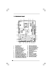
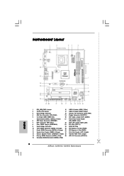
... Connector (ATXPWR1) (HD_AUDIO1, Lime) 7 IDE1 Connector (IDE1, Blue) 22 EUP LAN Jumper (EUP_LAN1) 8 Clear CMOS Jumper (CLRCMOS1) 23 PCI Slots (PCI1- 2) 9 South Bridge Controller 24 BIOS SPI Chip 10 Third SATAII Connector (SATAII_3; 1.3 Motherboard Layout 29 COM1 PS2 Mouse PS2 Keyboard...240-pin DDR2 DIMM Slots 20 EUP Audio Jumper (EUP_AUDIO1) (Dual Channel: DDRII_1, DDRII_2; Orange) 25 PCI Express x16 Slot (PCIE2) 11 Fourth SATAII Connector (SATAII_4; Orange) 26 PCI Express x1 Slot (PCIE1) 12 System Panel Header (PANEL1, Orange) 27 Print Port Header (LPT1, Purple) ...
... Connector (ATXPWR1) (HD_AUDIO1, Lime) 7 IDE1 Connector (IDE1, Blue) 22 EUP LAN Jumper (EUP_LAN1) 8 Clear CMOS Jumper (CLRCMOS1) 23 PCI Slots (PCI1- 2) 9 South Bridge Controller 24 BIOS SPI Chip 10 Third SATAII Connector (SATAII_3; 1.3 Motherboard Layout 29 COM1 PS2 Mouse PS2 Keyboard...240-pin DDR2 DIMM Slots 20 EUP Audio Jumper (EUP_AUDIO1) (Dual Channel: DDRII_1, DDRII_2; Orange) 25 PCI Express x16 Slot (PCIE2) 11 Fourth SATAII Connector (SATAII_4; Orange) 26 PCI Express x1 Slot (PCIE1) 12 System Panel Header (PANEL1, Orange) 27 Print Port Header (LPT1, Purple) ...
User Manual
Page 18
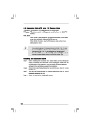
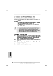
...slot and press firmly until the card is used for the card before you intend to use . Step 2. Step 3. Step 4. PCI slots: PCI slots are 2 PCI slots and 2 PCI Express slots on PCI Express VGA card to PCIE2 (PCIE x16 slot) and adjust the "Internal Graphics Mode Select" BIOS option to [Enabled, 8MB] or ...the onboard VGA will be enabled, and the primary screen will be onboard VGA. PCIE slots: PCIE1 (PCIE x1 slot) is completely seated on PCI Express VGA card to PCIE2 (PCIE x16 slot), the onboard VGA will be disabled. Installing an expansion card Step 1. Align the card connector with ...
...slot and press firmly until the card is used for the card before you intend to use . Step 2. Step 3. Step 4. PCI slots: PCI slots are 2 PCI slots and 2 PCI Express slots on PCI Express VGA card to PCIE2 (PCIE x16 slot) and adjust the "Internal Graphics Mode Select" BIOS option to [Enabled, 8MB] or ...the onboard VGA will be enabled, and the primary screen will be onboard VGA. PCIE slots: PCIE1 (PCIE x1 slot) is completely seated on PCI Express VGA card to PCIE2 (PCIE x16 slot), the onboard VGA will be disabled. Installing an expansion card Step 1. Align the card connector with ...
User Manual
Page 34
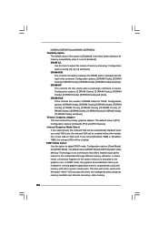
...11 DRAM Clocks], [12 DRAM Clocks], [13 DRAM Clocks], [14 DRAM Clocks], [15 DRAM Clocks] and [Auto]. Configuration options: [Onboard], [PCI] and [PCI Express]. Internal Graphics Mode Select If you select [Auto], the onboard VGA will be enabled. In Fixed mode, a fixed-size fragment of this item to ... the DRAM active command and the read / write command. DRAM tRP This controls the idle clocks after a precharge command is [PCI]. DRAM tRAS Thhis controls the number of memory accessing. the onboard VGA will intelligently detect physical memory available and allocate necessary video memory...
...11 DRAM Clocks], [12 DRAM Clocks], [13 DRAM Clocks], [14 DRAM Clocks], [15 DRAM Clocks] and [Auto]. Configuration options: [Onboard], [PCI] and [PCI Express]. Internal Graphics Mode Select If you select [Auto], the onboard VGA will be enabled. In Fixed mode, a fixed-size fragment of this item to ... the DRAM active command and the read / write command. DRAM tRP This controls the idle clocks after a precharge command is [PCI]. DRAM tRAS Thhis controls the number of memory accessing. the onboard VGA will intelligently detect physical memory available and allocate necessary video memory...
Quick Installation Guide
Page 2
Orange) 26 PCI Express x1 Slot (PCIE1) 12 System Panel Header (PANEL1, ...HD_AUDIO1, Lime) 7 IDE1 Connector (IDE1, Blue) 22 EUP LAN Jumper (EUP_LAN1) 8 Clear CMOS Jumper (CLRCMOS1) 23 PCI Slots (PCI1- 2) 9 South Bridge Controller 24 BIOS SPI Chip 10 Third SATAII Connector (SATAII_3; Motherboard Layout English 1 ... Audio Jumper (EUP_AUDIO1) (Dual Channel: DDRII_1, DDRII_2; Orange) 25 PCI Express x16 Slot (PCIE2) 11 Fourth SATAII Connector (SATAII_4; Red) 29 ATX 12V Connector (ATX12V1) 15 Secondary SATAII Connector (SATAII_2; Red) 2 ASRock G31M-GS / G31M-S Motherboard
Orange) 26 PCI Express x1 Slot (PCIE1) 12 System Panel Header (PANEL1, ...HD_AUDIO1, Lime) 7 IDE1 Connector (IDE1, Blue) 22 EUP LAN Jumper (EUP_LAN1) 8 Clear CMOS Jumper (CLRCMOS1) 23 PCI Slots (PCI1- 2) 9 South Bridge Controller 24 BIOS SPI Chip 10 Third SATAII Connector (SATAII_3; Motherboard Layout English 1 ... Audio Jumper (EUP_AUDIO1) (Dual Channel: DDRII_1, DDRII_2; Orange) 25 PCI Express x16 Slot (PCIE2) 11 Fourth SATAII Connector (SATAII_4; Red) 29 ATX 12V Connector (ATX12V1) 15 Secondary SATAII Connector (SATAII_2; Red) 2 ASRock G31M-GS / G31M-S Motherboard
Quick Installation Guide
Page 6
... slot - 1 x PCI Express x1 slot - 2 x PCI slots - Intel® Graphics Media Accelerator 3100 - capacity of system memory: 8GB (see CAUTION 5) - Supports Hyper-Threading Technology (see CAUTION 1) - Southbridge: Intel® ICH7 - G31M-S Realtek PCIE x1 LAN 8103EL / 8102EL, speed...- 4 x Ready-to 105W - Supports Wake-On-LAN I /O - Max. Compatible with LED (ACT/LINK LED and SPEED LED) 6 ASRock G31M-GS / G31M-S Motherboard English Supports Untied Overclocking Technology (see CAUTION 3) - Northbridge: Intel® G31 - Micro ATX Form Factor: 9.6-in x 7.2-in, 24.4 cm x...
... slot - 1 x PCI Express x1 slot - 2 x PCI slots - Intel® Graphics Media Accelerator 3100 - capacity of system memory: 8GB (see CAUTION 5) - Supports Hyper-Threading Technology (see CAUTION 1) - Southbridge: Intel® ICH7 - G31M-S Realtek PCIE x1 LAN 8103EL / 8102EL, speed...- 4 x Ready-to 105W - Supports Wake-On-LAN I /O - Max. Compatible with LED (ACT/LINK LED and SPEED LED) 6 ASRock G31M-GS / G31M-S Motherboard English Supports Untied Overclocking Technology (see CAUTION 3) - Northbridge: Intel® G31 - Micro ATX Form Factor: 9.6-in x 7.2-in, 24.4 cm x...
Quick Installation Guide
Page 14
... supply is switched off or the power cord is completely seated on this motherboard. PCIE slots: PCIE1 (PCIE x1 slot) is used for PCI Express cards with screws. 14 ASRock G31M-GS / G31M-S Motherboard English Installing an expansion card Step 1. Step 2. Fasten the card to the chassis with x16 lane width graphics cards. PCIE2 (PCIE...
... supply is switched off or the power cord is completely seated on this motherboard. PCIE slots: PCIE1 (PCIE x1 slot) is used for PCI Express cards with screws. 14 ASRock G31M-GS / G31M-S Motherboard English Installing an expansion card Step 1. Step 2. Fasten the card to the chassis with x16 lane width graphics cards. PCIE2 (PCIE...


