User Manual
Page 3
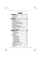
... 1.3 Motherboard Layout 10 1.4 I/O Panel 11 2 Installation 12 2.1 Screw Holes 12 2.2 Pre-installation Precautions 12 2.3 CPU Installation 13 2.4 Installation of Heatsink and CPU fan 15 2.5 Installation of Memory Modules (DIMM 16 2.6 Expansion Slots (PCI and PCI Express Slots 17 2.7 Jumpers...26 3.1.1 BIOS Menu Bar 26 3.1.2 Navigation Keys 27 3.2 Main Screen 27 3.3 Smart Screen 29 3.4 Advanced Screen 30 3.4.1 CPU Configuration 30 3.4.2 Chipset Configuration 32 3.4.3 ACPI Configuration 35 3.4.4 IDE Configuration 36 3.4.5 PCIPnP Configuration 38 3.4.6 Floppy Configuration 39 ...
... 1.3 Motherboard Layout 10 1.4 I/O Panel 11 2 Installation 12 2.1 Screw Holes 12 2.2 Pre-installation Precautions 12 2.3 CPU Installation 13 2.4 Installation of Heatsink and CPU fan 15 2.5 Installation of Memory Modules (DIMM 16 2.6 Expansion Slots (PCI and PCI Express Slots 17 2.7 Jumpers...26 3.1.1 BIOS Menu Bar 26 3.1.2 Navigation Keys 27 3.2 Main Screen 27 3.3 Smart Screen 29 3.4 Advanced Screen 30 3.4.1 CPU Configuration 30 3.4.2 Chipset Configuration 32 3.4.3 ACPI Configuration 35 3.4.4 IDE Configuration 36 3.4.5 PCIPnP Configuration 38 3.4.6 Floppy Configuration 39 ...
User Manual
Page 5
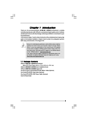
...CPU support lists on ASRock website without notice. ASRock website http://www.asrock.com If you are using. www.asrock.com/support/index.asp 1.1 Package Contents ASRock G31M-GS / G31M-S Motherboard (Micro ATX Form Factor: 9.6-in x 7.5-in, 24.4 cm x 19.1 cm) ASRock G31M-GS / G31M-S Quick Installation Guide ASRock G31M-GS / G31M...1 and 2 contain introduction of this motherboard, please visit our website for purchasing ASRock G31M-GS / G31M-S motherboard, a reliable motherboard produced under ASRock's consistently stringent quality control. Chapter 3 and 4 contain the configuration guide to...
...CPU support lists on ASRock website without notice. ASRock website http://www.asrock.com If you are using. www.asrock.com/support/index.asp 1.1 Package Contents ASRock G31M-GS / G31M-S Motherboard (Micro ATX Form Factor: 9.6-in x 7.5-in, 24.4 cm x 19.1 cm) ASRock G31M-GS / G31M-S Quick Installation Guide ASRock G31M-GS / G31M...1 and 2 contain introduction of this motherboard, please visit our website for purchasing ASRock G31M-GS / G31M-S motherboard, a reliable motherboard produced under ASRock's consistently stringent quality control. Chapter 3 and 4 contain the configuration guide to...
User Manual
Page 6
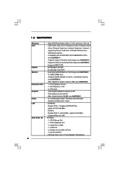
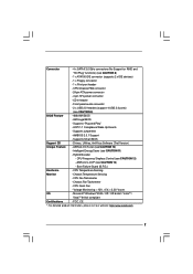
.../1066/800MHz CPUs (see CAUTION 6) - 1 x PCI Express x16 slot - 1 x PCI Express x1 slot - 2 x PCI slots - Southbridge: Intel® ICH7 - G31M-GS Realtek PCIE x 1 Gigabit LAN RTL8111DL, speed 10/100/1000 Mb/s - 1.2 Specifications Platform CPU Chipset Memory Expansion Slot Graphics Audio LAN Rear Panel I /O Panel - 1 x PS/2 Mouse Port - 1 x PS/2 Keyboard Port - 1 x Serial Port: COM1...
.../1066/800MHz CPUs (see CAUTION 6) - 1 x PCI Express x16 slot - 1 x PCI Express x1 slot - 2 x PCI slots - Southbridge: Intel® ICH7 - G31M-GS Realtek PCIE x 1 Gigabit LAN RTL8111DL, speed 10/100/1000 Mb/s - 1.2 Specifications Platform CPU Chipset Memory Expansion Slot Graphics Audio LAN Rear Panel I /O Panel - 1 x PS/2 Mouse Port - 1 x PS/2 Keyboard Port - 1 x Serial Port: COM1...
User Manual
Page 7
... and "Hot Plug" functions) (see CAUTION 13) - Boot Failure Guard (B.F.G.) Hardware - Chassis Fan Tachometer - AMBIOS 2.3.1 Support - CPU Fan Tachometer - FCC, CE * For detailed product information, please visit our website: http://www.asrock.com 7 CD in header - CPU/Chassis FAN connector - 24 pin ATX power connector - 4 pin 12V power connector - Supports "Plug and Play...
... and "Hot Plug" functions) (see CAUTION 13) - Boot Failure Guard (B.F.G.) Hardware - Chassis Fan Tachometer - AMBIOS 2.3.1 Support - CPU Fan Tachometer - FCC, CE * For detailed product information, please visit our website: http://www.asrock.com 7 CD in header - CPU/Chassis FAN connector - 24 pin ATX power connector - 4 pin 12V power connector - Supports "Plug and Play...
User Manual
Page 8
... SATAII hard disk drive to page 19 for the latest information. 8. ASRock website: http://www.asrock.com 8 It should be done at your system by overclocking. Please check the table below for details. 4. CPU FSB Frequency Memory Support Frequency 1600 DDR2 800 1333 DDR2 667, DDR2 ...connect SATA hard disk to adjust the jumpers. It is a user-friendly ASRock overclocking tool which allows you implement Dual Channel Memory Technology, make sure to surveil your own risk and expense. FSB1600-CPU will also be less than 4GB for the reservation for proper installation. 5....
... SATAII hard disk drive to page 19 for the latest information. 8. ASRock website: http://www.asrock.com 8 It should be done at your system by overclocking. Please check the table below for details. 4. CPU FSB Frequency Memory Support Frequency 1600 DDR2 800 1333 DDR2 667, DDR2 ...connect SATA hard disk to adjust the jumpers. It is a user-friendly ASRock overclocking tool which allows you implement Dual Channel Memory Technology, make sure to surveil your own risk and expense. FSB1600-CPU will also be less than 4GB for the reservation for proper installation. 5....
User Manual
Page 9
...dissipation, remember to provide exceptional power saving and improve power efficiency without sacrificing computing performance. ASRock website: http://www.asrock.com 12. Although this motherboard offers stepless control, it back again. Before you install... the PC system. 9 11. In other than the recommended CPU bus frequencies may cause the instability of Intelligent Energy Saver. Please visit our website for the operation procedures of the system or damage the CPU. 13. While CPU...
...dissipation, remember to provide exceptional power saving and improve power efficiency without sacrificing computing performance. ASRock website: http://www.asrock.com 12. Although this motherboard offers stepless control, it back again. Before you install... the PC system. 9 11. In other than the recommended CPU bus frequencies may cause the instability of Intelligent Energy Saver. Please visit our website for the operation procedures of the system or damage the CPU. 13. While CPU...
User Manual
Page 10
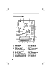
... 15 14 13 12 SATAII_2 SATAII_4 6 7 8 9 10 11 1 PS2_USB_PWR1 Jumper 15 USB 2.0 Header (USB6_7, Blue) 2 775-Pin CPU Socket 16 USB 2.0 Header (USB4_5, Blue) 3 North Bridge Controller 17 System Panel Header (PANEL1, Orange) 4 CPU Fan Connector (CPU_FAN1) 18 BIOS SPI Chip 5 2 x 240-pin DDR2 DIMM Slots 19 Chassis Fan Connector (CHA_FAN1) (Dual...
... 15 14 13 12 SATAII_2 SATAII_4 6 7 8 9 10 11 1 PS2_USB_PWR1 Jumper 15 USB 2.0 Header (USB6_7, Blue) 2 775-Pin CPU Socket 16 USB 2.0 Header (USB4_5, Blue) 3 North Bridge Controller 17 System Panel Header (PANEL1, Orange) 4 CPU Fan Connector (CPU_FAN1) 18 BIOS SPI Chip 5 2 x 240-pin DDR2 DIMM Slots 19 Chassis Fan Connector (CHA_FAN1) (Dual...
User Manual
Page 13
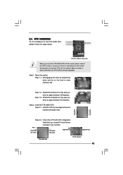
... depressing down and out on the socket. Locate Pin1 and the two orientation key notches. Otherwise, the CPU will be seriously damaged. Rotate the load plate to fully open position at approximately 135 degrees. black line black line Step 2-2. Rotate the ...fully open position at approximately 100 degrees. Step 2. Pin1 orientation key notch orientation key notch Pin1 alignment key alignment key 775-LAND CPU 775-Pin Socket 13 2.3 CPU Installation For the installation of Intel 775-LAND CPU, please follow the steps below. 775-Pin Socket Overview Before you insert the 775-LAND...
... depressing down and out on the socket. Locate Pin1 and the two orientation key notches. Otherwise, the CPU will be seriously damaged. Rotate the load plate to fully open position at approximately 135 degrees. black line black line Step 2-2. Rotate the ...fully open position at approximately 100 degrees. Step 2. Pin1 orientation key notch orientation key notch Pin1 alignment key alignment key 775-LAND CPU 775-Pin Socket 13 2.3 CPU Installation For the installation of Intel 775-LAND CPU, please follow the steps below. 775-Pin Socket Overview Before you insert the 775-LAND...

User Manual
Page 14
... recommended to use the cap tab to match the two orientation key notches of the CPU with the two alignment keys of the socket. Remove PnP Cap (Pick and Place Cap): Use your left hand index finger and thumb to support ... ensure to handle and avoid kicking off the PnP cap. 2. This cap must be placed if returning the motherboard for after service. Carefully place the CPU into the socket by using a purely vertical motion. Rotate the load plate onto the IHS. Step 2-3. Step 4-2.
... recommended to use the cap tab to match the two orientation key notches of the CPU with the two alignment keys of the socket. Remove PnP Cap (Pick and Place Cap): Use your left hand index finger and thumb to support ... ensure to handle and avoid kicking off the PnP cap. 2. This cap must be placed if returning the motherboard for after service. Carefully place the CPU into the socket by using a purely vertical motion. Rotate the load plate onto the IHS. Step 2-3. Step 4-2.
User Manual
Page 15
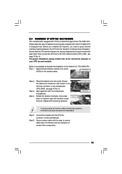
...on the socket surface. Repeat with fan operation or contact other . Connect fan header with the CPU fan connector on fastener caps with Intel 775-LAND CPU to dissipate heat. Then connect the CPU fan to the CPU_FAN connector (CPU_FAN1, see page 10, No. 4). If you need to ...heatsink, you press down on the motherboard. Below is equipped with the motherboard throughholes. Step 3. Align fasteners with 775-Pin socket that the CPU and the heatsink are oriented on side closest to improve heat dissipation. Place the heatsink onto the socket. Step 5. Step 1. Apply thermal ...
...on the socket surface. Repeat with fan operation or contact other . Connect fan header with the CPU fan connector on fastener caps with Intel 775-LAND CPU to dissipate heat. Then connect the CPU fan to the CPU_FAN connector (CPU_FAN1, see page 10, No. 4). If you need to ...heatsink, you press down on the motherboard. Below is equipped with the motherboard throughholes. Step 3. Align fasteners with 775-Pin socket that the CPU and the heatsink are oriented on side closest to improve heat dissipation. Place the heatsink onto the socket. Step 5. Step 1. Apply thermal ...
User Manual
Page 19
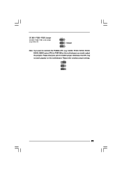
Please refer to overclock the FSB800-CPU (e.g. Please short pin2, pin3 for OC800 jumper. Cel400, E1000, E2000, E4000, E5000, E6000 series CPU) to adjust the jumpers. OC 800 / FSB0 / FSB1 Jumper (OC 800 / FSB0 / FSB1, 3-pin jumper, see p.10 No. 27) 1_2 1_2 Default 1_2 Note: If you need to FSB1066 on this motherboard. Otherwise, the CPU may not work properly on this motherboard, you want to below jumper settings. 2_3 1_2 1_2 19
Please refer to overclock the FSB800-CPU (e.g. Please short pin2, pin3 for OC800 jumper. Cel400, E1000, E2000, E4000, E5000, E6000 series CPU) to adjust the jumpers. OC 800 / FSB0 / FSB1 Jumper (OC 800 / FSB0 / FSB1, 3-pin jumper, see p.10 No. 27) 1_2 1_2 Default 1_2 Note: If you need to FSB1066 on this motherboard. Otherwise, the CPU may not work properly on this motherboard, you want to below jumper settings. 2_3 1_2 1_2 19
User Manual
Page 22
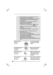
... Header (4-pin SPEAKER 1) (see p.10 No. 14) Chassis Fan Connector (3-pin CHA_FAN1) (see p.10 No. 4) 22 4 3 2 1 GND +12V CPU_FAN_SPEED FAN_SPEED_CONTROL Please connect a CPU fan cable to this header. CPU Fan Connector (4-pin CPU_FAN1) (see p.10 No. 19) PLED+ PLEDPWRBTN# GND 1 DUMMY RESET# GND HDLEDHDLED+ 1 SPEAKER DUMMY DUMMY +5V This header accommodates several...
... Header (4-pin SPEAKER 1) (see p.10 No. 14) Chassis Fan Connector (3-pin CHA_FAN1) (see p.10 No. 4) 22 4 3 2 1 GND +12V CPU_FAN_SPEED FAN_SPEED_CONTROL Please connect a CPU fan cable to this header. CPU Fan Connector (4-pin CPU_FAN1) (see p.10 No. 19) PLED+ PLEDPWRBTN# GND 1 DUMMY RESET# GND HDLEDHDLED+ 1 SPEAKER DUMMY DUMMY +5V This header accommodates several...
User Manual
Page 23
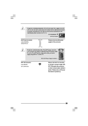
... connector. 1 13 Though this motherboard provides 24-pin ATX power connector, 12 24 it can work if you plan to connect the 3-Pin CPU fan to the CPU fan connector on this motherboard, please connect it can provides sufficient power. Pin 1-3 Connected 3-Pin Fan Installation ATX Power Connector (24-pin ATXPWR1... (see p.10 No. 28) Please note that it to Pin 1-3. If you adopt a traditional 20-pin ATX power supply. Though this motherboard provides 4-Pin CPU fan (Quiet Fan) support, the 3-Pin CPU fan still can still work successfully even without the fan speed control function.
... connector. 1 13 Though this motherboard provides 24-pin ATX power connector, 12 24 it can work if you plan to connect the 3-Pin CPU fan to the CPU fan connector on this motherboard, please connect it can provides sufficient power. Pin 1-3 Connected 3-Pin Fan Installation ATX Power Connector (24-pin ATXPWR1... (see p.10 No. 28) Please note that it to Pin 1-3. If you adopt a traditional 20-pin ATX power supply. Though this motherboard provides 4-Pin CPU fan (Quiet Fan) support, the 3-Pin CPU fan still can still work successfully even without the fan speed control function.
User Manual
Page 25
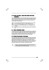
... disks. Therefore, the drivers you enable Untied Overclocking function, please enter "Overclock Mode" option of your optical drive first. Therefore, CPU FSB is untied during overclocking, FSB enjoys better margin due to [CPU, PCIE, Async.]. You may install SATA / SATAII hard disks on page 8 for internal storage devices. STEP 3: Connect one end...
... disks. Therefore, the drivers you enable Untied Overclocking function, please enter "Overclock Mode" option of your optical drive first. Therefore, CPU FSB is untied during overclocking, FSB enjoys better margin due to [CPU, PCIE, Async.]. You may install SATA / SATAII hard disks on page 8 for internal storage devices. STEP 3: Connect one end...
User Manual
Page 27
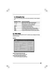
... the current screen 3.2 Main Screen When you enter the BIOS SETUP UTILITY, the Main screen will appear and display the system overview G31M-GS BIOS SETUP UTILITY Main Smart Advanced H/W Monitor Boot Security Exit System Overview System Time System Date [14:00:09] [Thu 07/31.../2008] BIOS Version : G31M-GS P1.00 Processor Type : Intel(R) Core(TM) 2 Duo CPU E6540 @ 2.33GHz (64bit) Processor Speed : 2333MHz Microcode Update : 6FB/B6 Cache Size : 4096KB Total Memory DDRII 1 DDRII 2...
... the current screen 3.2 Main Screen When you enter the BIOS SETUP UTILITY, the Main screen will appear and display the system overview G31M-GS BIOS SETUP UTILITY Main Smart Advanced H/W Monitor Boot Security Exit System Overview System Time System Date [14:00:09] [Thu 07/31.../2008] BIOS Version : G31M-GS P1.00 Processor Type : Intel(R) Core(TM) 2 Duo CPU E6540 @ 2.33GHz (64bit) Processor Speed : 2333MHz Microcode Update : 6FB/B6 Cache Size : 4096KB Total Memory DDRII 1 DDRII 2...
User Manual
Page 28
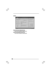
...system date. 28 Use [+] or [-] to select a field. System Time [Hour:Minute:Second] Use this item to specify the system time. G31M-S BIOS SETUP UTILITY Main Smart Advanced H/W Monitor Boot Security Exit System Overview System Time System Date [14:00:09] [Thu 07/31/2008...] BIOS Version : G31M-S P1.00 Processor Type : Intel(R) Core(TM) 2 Duo CPU E6540 @ 2.33GHz (64bit) Processor Speed : 2333MHz Microcode Update : 6FB/B6 Cache Size : 4096KB Total Memory DDRII 1 DDRII 2...
...system date. 28 Use [+] or [-] to select a field. System Time [Hour:Minute:Second] Use this item to specify the system time. G31M-S BIOS SETUP UTILITY Main Smart Advanced H/W Monitor Boot Security Exit System Overview System Time System Date [14:00:09] [Thu 07/31/2008...] BIOS Version : G31M-S P1.00 Processor Type : Intel(R) Core(TM) 2 Duo CPU E6540 @ 2.33GHz (64bit) Processor Speed : 2333MHz Microcode Update : 6FB/B6 Cache Size : 4096KB Total Memory DDRII 1 DDRII 2...
User Manual
Page 30
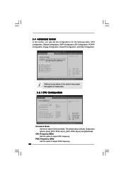
...Copyright 1985-2005, American Megatrends, Inc. PCIE Frequency (MHz) Use this section may set the configurations for CPU CPU Configuration Chipset Configuration ACPI Configuration IDE Configuration PCIPnP Configuration Floppy Configuration SuperIO Configuration USB Configuration Select Screen Select Item Enter Go to...Guard Spread Spectrum Ratio Actual Value Enhance Halt State Intel (R) Virtualization tech. 3.4 Advanced Screen In this to select Overclock Mode. CPU Frequency (MHz) Use this option to Sub Screen F1 General Help F9 Load Defaults F10 Save and Exit ESC Exit v02.54 ...
...Copyright 1985-2005, American Megatrends, Inc. PCIE Frequency (MHz) Use this section may set the configurations for CPU CPU Configuration Chipset Configuration ACPI Configuration IDE Configuration PCIPnP Configuration Floppy Configuration SuperIO Configuration USB Configuration Select Screen Select Item Enter Go to...Guard Spread Spectrum Ratio Actual Value Enhance Halt State Intel (R) Virtualization tech. 3.4 Advanced Screen In this to select Overclock Mode. CPU Frequency (MHz) Use this option to Sub Screen F1 General Help F9 Load Defaults F10 Save and Exit ESC Exit v02.54 ...
User Manual
Page 31
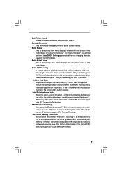
...the ratio value of this motherboard. No-Excute Memory Protection No-Execution (NX) Memory Protection Technology is an enhancement to keep the CPU from overheated. Boot Failure Guard Enable or disable the feature of this motherboard is "Locked" or "Unlocked". If the... a VMM (Virtual Machine Architecture) can prevent data pages from the chipset. Spread Spectrum This item should always be hidden if the current CPU does not support CPU Thermal Throttling. When this option is unlocked, you will be [Auto] for better system stability. Ratio Status This is supported through the ...
...the ratio value of this motherboard. No-Excute Memory Protection No-Execution (NX) Memory Protection Technology is an enhancement to keep the CPU from overheated. Boot Failure Guard Enable or disable the feature of this motherboard is "Locked" or "Unlocked". If the... a VMM (Virtual Machine Architecture) can prevent data pages from the chipset. Spread Spectrum This item should always be hidden if the current CPU does not support CPU Thermal Throttling. When this option is unlocked, you will be [Auto] for better system stability. Ratio Status This is supported through the ...
User Manual
Page 32
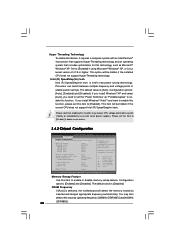
...Exit v02.54 (C) Copyright 1985-2005, American Megatrends, Inc. Configuration options: [Enabled] and [Disabled]. This option will be hidden if the current CPU does not support Intel (R) SpeedStep(tm) tech.. Intel (R) SpeedStep(tm) tech. The default value is [Auto]. Intel (R) SpeedStep(tm) tech...: Do not allow remapping of overlapped PCI memory above the total physical memory. is selected, the motherboard will be hidden if the installed CPU does not support Hyper-Threading technology. Configuration options: [Auto], [Enabled] and [Disabled]. DRAM Frequency If [Auto] is Intel's new...
...Exit v02.54 (C) Copyright 1985-2005, American Megatrends, Inc. Configuration options: [Enabled] and [Disabled]. This option will be hidden if the current CPU does not support Intel (R) SpeedStep(tm) tech.. Intel (R) SpeedStep(tm) tech. The default value is [Auto]. Intel (R) SpeedStep(tm) tech...: Do not allow remapping of overlapped PCI memory above the total physical memory. is selected, the motherboard will be hidden if the installed CPU does not support Hyper-Threading technology. Configuration options: [Auto], [Enabled] and [Disabled]. DRAM Frequency If [Auto] is Intel's new...
User Manual
Page 41
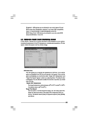
... use only under legacy OS and BIOS setup when [Disabled] is [50 C/122 F]. If you to identify the temperature of the CPU temperature, motherboard temperature, CPU fan speed, chassis fan speed, and the critical voltage. You are allowed to allow you to monitor the status of the hardware on... your system, including the parameters of CPU fan. F1 F9 F10 ESC Select Screen Select Item General Help Load Defaults Save and Exit Exit v02.54 (C) Copyright 1985-2003, American ...
... use only under legacy OS and BIOS setup when [Disabled] is [50 C/122 F]. If you to identify the temperature of the CPU temperature, motherboard temperature, CPU fan speed, chassis fan speed, and the critical voltage. You are allowed to allow you to monitor the status of the hardware on... your system, including the parameters of CPU fan. F1 F9 F10 ESC Select Screen Select Item General Help Load Defaults Save and Exit Exit v02.54 (C) Copyright 1985-2003, American ...


