User Manual
Page 3
... 5 1.2 Specifications 6 1.3 Motherboard Layout 10 1.4 I/O Panel (G31M-GS 11 1.5 I/O Panel (G31M-S 12 2 Installation 13 2.1 Screw Holes 13 2.2 Pre-installation Precautions 13 2.3 CPU Installation 14 2.4 Installation of Heatsink and CPU fan 16 2.5 Installation of Memory Modules (DIMM 17 2.6 Expansion ... BIOS Menu Bar 27 3.1.2 Navigation Keys 28 3.2 Main Screen 28 3.3 Smart Screen 30 3.4 Advanced Screen 31 3.4.1 CPU Configuration 31 3.4.2 Chipset Configuration 33 3.4.3 ACPI Configuration 36 3.4.4 IDE Configuration 37 3.4.5 PCIPnP Configuration 39 3.4.6 Floppy Configuration ...
... 5 1.2 Specifications 6 1.3 Motherboard Layout 10 1.4 I/O Panel (G31M-GS 11 1.5 I/O Panel (G31M-S 12 2 Installation 13 2.1 Screw Holes 13 2.2 Pre-installation Precautions 13 2.3 CPU Installation 14 2.4 Installation of Heatsink and CPU fan 16 2.5 Installation of Memory Modules (DIMM 17 2.6 Expansion ... BIOS Menu Bar 27 3.1.2 Navigation Keys 28 3.2 Main Screen 28 3.3 Smart Screen 30 3.4 Advanced Screen 31 3.4.1 CPU Configuration 31 3.4.2 Chipset Configuration 33 3.4.3 ACPI Configuration 36 3.4.4 IDE Configuration 37 3.4.5 PCIPnP Configuration 39 3.4.6 Floppy Configuration ...
User Manual
Page 5
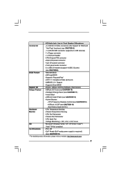
...further notice. www.asrock.com/support/index.asp 1.1 Package Contents ASRock G31M-GS / G31M-S Motherboard (Micro ATX Form Factor: 9.6-in x 7.2-in, 24.4 cm x 18.3 cm) ASRock G31M-GS / G31M-S Quick Installation Guide ASRock G31M-GS / G31M-S Support CD ...One 80-conductor Ultra ATA 66/100 IDE Ribbon Cable (Optional) One Serial ATA (SATA) Data Cable (Optional) One I/O Panel Shield 5 ASRock website http://www.asrock.com If you are using. You may find the latest VGA cards and CPU support lists on ASRock...
...further notice. www.asrock.com/support/index.asp 1.1 Package Contents ASRock G31M-GS / G31M-S Motherboard (Micro ATX Form Factor: 9.6-in x 7.2-in, 24.4 cm x 18.3 cm) ASRock G31M-GS / G31M-S Quick Installation Guide ASRock G31M-GS / G31M-S Support CD ...One 80-conductor Ultra ATA 66/100 IDE Ribbon Cable (Optional) One Serial ATA (SATA) Data Cable (Optional) One I/O Panel Shield 5 ASRock website http://www.asrock.com If you are using. You may find the latest VGA cards and CPU support lists on ASRock...

User Manual
Page 6
... Keyboard Port - 1 x Serial Port: COM1 - 1 x VGA Port - 4 x Ready-to 105W - Max. G31M-S Realtek PCIE x1 LAN 8103EL / 8102EL, speed 10/100 Mb/s - Pixel Shader 2.0, DirectX 9.0 - Supports CPU up to -Use USB 2.0 Ports - 1 x RJ-45 LAN Port with all FSB1600/1333/1066/800MHz CPUs (see ... Windows® VistaTM Premium Level HD Audio (Realtek ALC662 Audio Codec) - Compatible with LED (ACT/LINK LED and SPEED LED) Supports EM64T CPU - G31M-GS Realtek PCIE x 1 Gigabit LAN RTL8111DL, speed 10/100/1000 Mb/s - Intel® Graphics Media Accelerator 3100 - Micro ATX Form Factor...
... Keyboard Port - 1 x Serial Port: COM1 - 1 x VGA Port - 4 x Ready-to 105W - Max. G31M-S Realtek PCIE x1 LAN 8103EL / 8102EL, speed 10/100 Mb/s - Pixel Shader 2.0, DirectX 9.0 - Supports CPU up to -Use USB 2.0 Ports - 1 x RJ-45 LAN Port with all FSB1600/1333/1066/800MHz CPUs (see ... Windows® VistaTM Premium Level HD Audio (Realtek ALC662 Audio Codec) - Compatible with LED (ACT/LINK LED and SPEED LED) Supports EM64T CPU - G31M-GS Realtek PCIE x 1 Gigabit LAN RTL8111DL, speed 10/100/1000 Mb/s - Intel® Graphics Media Accelerator 3100 - Micro ATX Form Factor...
User Manual
Page 7
... 15) * For detailed product information, please visit our website: http://www.asrock.com 7 ASRock U-COP (see CAUTION 13) - Boot Failure Guard (B.F.G.) Hardware - Chassis Temperature Sensing - Voltage Monitoring: +12V, +5V, +3.3V, Vcore OS - Instant Boot - Hybrid Booster: - CPU Fan Tachometer - Supports "Plug and Play" - CPU Frequency Stepless Control (see CAUTION 14) - - AMBIOS 2.3.1 Support - Drivers, Utilities...
... 15) * For detailed product information, please visit our website: http://www.asrock.com 7 ASRock U-COP (see CAUTION 13) - Boot Failure Guard (B.F.G.) Hardware - Chassis Temperature Sensing - Voltage Monitoring: +12V, +5V, +3.3V, Vcore OS - Instant Boot - Hybrid Booster: - CPU Fan Tachometer - Supports "Plug and Play" - CPU Frequency Stepless Control (see CAUTION 14) - - AMBIOS 2.3.1 Support - Drivers, Utilities...

User Manual
Page 8
... The maximum shared memory size is defined by overclocking. WARNING Please realize that there is a certain risk involved with 64-bit CPU, there is no such limitation. 7. Under this situation, PCIE frequency will operate in the BIOS, applying Untied Overclocking Technology, ...or using the thirdparty overclocking tools. Power Management for proper installation. 5. If you adopt FSB1600-CPU, you implement Dual Channel Memory Technology, make sure to adjust the jumpers. Please check the table below for proper jumper settings....
... The maximum shared memory size is defined by overclocking. WARNING Please realize that there is a certain risk involved with 64-bit CPU, there is no such limitation. 7. Under this situation, PCIE frequency will operate in the BIOS, applying Untied Overclocking Technology, ...or using the thirdparty overclocking tools. Power Management for proper installation. 5. If you adopt FSB1600-CPU, you implement Dual Channel Memory Technology, make sure to adjust the jumpers. Please check the table below for proper jumper settings....
User Manual
Page 9
...BIOS without preparing an additional floppy diskette or other complicated flash utility. While CPU overheat is higher than the recommended CPU bus frequencies may cause the instability of ASRock OC Tuner. ASRock website: http://www.asrock.com 12. EuP, stands for Energy Using Product, was a provision ... more details. 9 10. With this motherboard offers stepless control, it is a user-friendly ASRock overclocking tool which allows you resume the system, please check if the CPU fan on the motherboard functions properly and unplug the power cord, then plug it is able...
...BIOS without preparing an additional floppy diskette or other complicated flash utility. While CPU overheat is higher than the recommended CPU bus frequencies may cause the instability of ASRock OC Tuner. ASRock website: http://www.asrock.com 12. EuP, stands for Energy Using Product, was a provision ... more details. 9 10. With this motherboard offers stepless control, it is a user-friendly ASRock overclocking tool which allows you resume the system, please check if the CPU fan on the motherboard functions properly and unplug the power cord, then plug it is able...

User Manual
Page 10
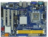
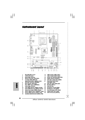
..., 240-piFnSmBod8ul0e)0 24.4cm (9.6 in) SATAII_3 SATAII_4 6 7 8 9 10 11 1 PS2_USB_PWR1 Jumper 16 USB 2.0 Header (USB6_7, Blue) 2 775-Pin CPU Socket 17 USB 2.0 Header (USB4_5, Blue) 3 North Bridge Controller 18 Chassis Fan Connector (CHA_FAN1) 4 CPU Fan Connector (CPU_FAN1) 19 Floppy Connector (FLOPPY1) 5 2 x 240-pin DDR2 DIMM Slots 20 EUP Audio Jumper (EUP_AUDIO1) (Dual...
..., 240-piFnSmBod8ul0e)0 24.4cm (9.6 in) SATAII_3 SATAII_4 6 7 8 9 10 11 1 PS2_USB_PWR1 Jumper 16 USB 2.0 Header (USB6_7, Blue) 2 775-Pin CPU Socket 17 USB 2.0 Header (USB4_5, Blue) 3 North Bridge Controller 18 Chassis Fan Connector (CHA_FAN1) 4 CPU Fan Connector (CPU_FAN1) 19 Floppy Connector (FLOPPY1) 5 2 x 240-pin DDR2 DIMM Slots 20 EUP Audio Jumper (EUP_AUDIO1) (Dual...
User Manual
Page 14
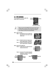
... follow the steps below. 775-Pin Socket Overview Before you insert the 775-LAND CPU into the socket if above situation is any bent pin on the ShoockoetkMatrokedcCleoranerr retention tab. Otherwise, the CPU will be seriously damaged. Step 1-3. Step 2-2. Step 2. Rotate the load lever to... fully open position at approximately 135 degrees. Insert the 775-LAND CPU: Step 2-1. Step 1. DLifitsLeevnergUapgtoin9g0° the lever by the edges where are marked with IHS (Integrated Heat Sink) up. Hold the CPU by depressing down and out on the socket. Pin1 orientation key ...
... follow the steps below. 775-Pin Socket Overview Before you insert the 775-LAND CPU into the socket if above situation is any bent pin on the ShoockoetkMatrokedcCleoranerr retention tab. Otherwise, the CPU will be seriously damaged. Step 1-3. Step 2-2. Step 2. Rotate the load lever to... fully open position at approximately 135 degrees. Insert the 775-LAND CPU: Step 2-1. Step 1. DLifitsLeevnergUapgtoin9g0° the lever by the edges where are marked with IHS (Integrated Heat Sink) up. Hold the CPU by depressing down and out on the socket. Pin1 orientation key ...
User Manual
Page 15
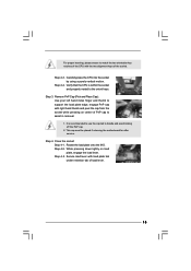
...of PnP cap to assist in removal. 1. Step 2-4. This cap must be placed if returning the motherboard for after service. Step 4-3. Step 2-3. Verify that the CPU is recommended to use the cap tab to handle and avoid kicking off the PnP cap. 2. Step 3. Remove PnP Cap (Pick and Place Cap): Use...: Step 4-1. Step 4-2. Secure load lever with the two alignment keys of the socket. Rotate the load plate onto the IHS. Step 4. Carefully place the CPU into the socket by using a purely vertical motion. For proper inserting, please ensure to match the two orientation key notches of the...
...of PnP cap to assist in removal. 1. Step 2-4. This cap must be placed if returning the motherboard for after service. Step 4-3. Step 2-3. Verify that the CPU is recommended to use the cap tab to handle and avoid kicking off the PnP cap. 2. Step 3. Remove PnP Cap (Pick and Place Cap): Use...: Step 4-1. Step 4-2. Secure load lever with the two alignment keys of the socket. Rotate the load plate onto the IHS. Step 4. Carefully place the CPU into the socket by using a purely vertical motion. For proper inserting, please ensure to match the two orientation key notches of the...
User Manual
Page 16
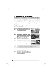
..., see page 10, No. 4). Place the heatsink onto the socket. Connect fan header with each other components. 16 Then connect the CPU fan to the instruction manuals of your CPU fan and heatsink. Step 1. Ensure fan cables are securely fastened and in good contact with the... connector on the socket surface. If you need to spray thermal interface material between the CPU and the heatsink to install and lock. Ensure that supports Intel 775-LAND CPU. Step 2. Step 4. Secure excess cable with fan operation or contact other . Rotate the fastener clockwise, then press ...
..., see page 10, No. 4). Place the heatsink onto the socket. Connect fan header with each other components. 16 Then connect the CPU fan to the instruction manuals of your CPU fan and heatsink. Step 1. Ensure fan cables are securely fastened and in good contact with the... connector on the socket surface. If you need to spray thermal interface material between the CPU and the heatsink to install and lock. Ensure that supports Intel 775-LAND CPU. Step 2. Step 4. Secure excess cable with fan operation or contact other . Rotate the fastener clockwise, then press ...
User Manual
Page 20
... 2_3 1_2 1_2 20 Please short pin2, pin3 for OC800 jumper. Please refer to below jumper settings. 2_3 1_2 1_2 Note: If you adopt FSB1600-CPU on this motherboard, you need to adjust the jumpers. Cel400, E1000, E2000, E4000, E5000, E6000 series... CPU) to FSB1066 on this motherboard, you want to overclock the FSB800-CPU (e.g. Please short pin2, pin3 for OC800 jumper. Otherwise, the CPU may not work properly on this motherboard. OC 800 / FSB0 / FSB1 Jumper (OC 800 / FSB0...
... 2_3 1_2 1_2 20 Please short pin2, pin3 for OC800 jumper. Please refer to below jumper settings. 2_3 1_2 1_2 Note: If you adopt FSB1600-CPU on this motherboard, you need to adjust the jumpers. Cel400, E1000, E2000, E4000, E5000, E6000 series... CPU) to FSB1066 on this motherboard, you want to overclock the FSB800-CPU (e.g. Please short pin2, pin3 for OC800 jumper. Otherwise, the CPU may not work properly on this motherboard. OC 800 / FSB0 / FSB1 Jumper (OC 800 / FSB0...

User Manual
Page 23
...cable to this connector and match the black wire to make the Front Mic as default record device. CPU Fan Connector (4-pin CPU_FAN1) (see p.10 No. 4) 4 3 2 1 GND +12V CPU_FAN_SPEED FAN_SPEED_CONTROL Please connect a CPU fan cable to this motherboard, please connect it to Pin 1-3. If you want to this motherboard provides ...the front mic. For Windows® VistaTM / VistaTM 64-bit OS: Go to the ground pin. If you plan to connect the 3-Pin CPU fan to the CPU fan connector on this connector and match the black wire to the "Front Mic" Tab in "Front Mic" of "Playback" portion. Click ...
...cable to this connector and match the black wire to make the Front Mic as default record device. CPU Fan Connector (4-pin CPU_FAN1) (see p.10 No. 4) 4 3 2 1 GND +12V CPU_FAN_SPEED FAN_SPEED_CONTROL Please connect a CPU fan cable to this motherboard, please connect it to Pin 1-3. If you want to this motherboard provides ...the front mic. For Windows® VistaTM / VistaTM 64-bit OS: Go to the ground pin. If you plan to connect the 3-Pin CPU fan to the CPU fan connector on this connector and match the black wire to the "Front Mic" Tab in "Front Mic" of "Playback" portion. Click ...
User Manual
Page 26
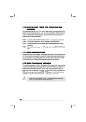
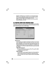
...on page 8 for internal storage devices. Please follow the order from [Auto] to install the SATA / SATAII hard disks. Therefore, CPU FSB is untied during overclocking, FSB enjoys better margin due to the motherboard's SATAII connector. Therefore, the drivers you enable Untied Overclocking function...SATA data cable to fixed PCI / PCIE buses. Please refer to the warning on this motherboard for the possible overclocking risk before you to [CPU, PCIE, Async.]. This section will guide you apply Untied Overclocking Technology. 26 2 . 1 0 Serial ATA (SATA) / Serial ATAII (...
...on page 8 for internal storage devices. Please follow the order from [Auto] to install the SATA / SATAII hard disks. Therefore, CPU FSB is untied during overclocking, FSB enjoys better margin due to the motherboard's SATAII connector. Therefore, the drivers you enable Untied Overclocking function...SATA data cable to fixed PCI / PCIE buses. Please refer to the warning on this motherboard for the possible overclocking risk before you to [CPU, PCIE, Async.]. This section will guide you apply Untied Overclocking Technology. 26 2 . 1 0 Serial ATA (SATA) / Serial ATAII (...
User Manual
Page 28
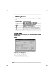
... the current screen 3.2 Main Screen When you enter the BIOS SETUP UTILITY, the Main screen will appear and display the system overview G31M-GS BIOS SETUP UTILITY Main Smart Advanced H/W Monitor Boot Security Exit System Overview System Time System Date [14:00:09] [Mon 06/15.../2009] BIOS Version : G31M-GS P1.00 Processor Type : Intel(R) Core(TM) 2 Duo CPU E6540 @ 2.33GHz (64bit) Processor Speed : 2333MHz Microcode Update : 6FB/B6 Cache Size : 4096KB Total Memory DDRII 1 DDRII 2...
... the current screen 3.2 Main Screen When you enter the BIOS SETUP UTILITY, the Main screen will appear and display the system overview G31M-GS BIOS SETUP UTILITY Main Smart Advanced H/W Monitor Boot Security Exit System Overview System Time System Date [14:00:09] [Mon 06/15.../2009] BIOS Version : G31M-GS P1.00 Processor Type : Intel(R) Core(TM) 2 Duo CPU E6540 @ 2.33GHz (64bit) Processor Speed : 2333MHz Microcode Update : 6FB/B6 Cache Size : 4096KB Total Memory DDRII 1 DDRII 2...
User Manual
Page 29
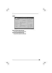
...system date. 29 Use [+] or [-] to select a field. System Time [Hour:Minute:Second] Use this item to specify the system time. G31M-S BIOS SETUP UTILITY Main Smart Advanced H/W Monitor Boot Security Exit System Overview System Time System Date [14:00:09] [Mon 06/15/2009...] BIOS Version : G31M-S P1.00 Processor Type : Intel(R) Core(TM) 2 Duo CPU E6540 @ 2.33GHz (64bit) Processor Speed : 2333MHz Microcode Update : 6FB/B6 Cache Size : 4096KB Total Memory DDRII 1 DDRII 2...
...system date. 29 Use [+] or [-] to select a field. System Time [Hour:Minute:Second] Use this item to specify the system time. G31M-S BIOS SETUP UTILITY Main Smart Advanced H/W Monitor Boot Security Exit System Overview System Time System Date [14:00:09] [Mon 06/15/2009...] BIOS Version : G31M-S P1.00 Processor Type : Intel(R) Core(TM) 2 Duo CPU E6540 @ 2.33GHz (64bit) Processor Speed : 2333MHz Microcode Update : 6FB/B6 Cache Size : 4096KB Total Memory DDRII 1 DDRII 2...
User Manual
Page 31
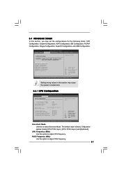
...Min: 12, Max: 17) 17 Enhanced Halt State CPU Thermal Throttling No-Excute Memory Protection Intel (R) SpeedStep (R) tech. The default value is [Auto]. Cnfiguration options: [Auto], [CPU, PCIE, Sync.], [CPU, PCIE, Async.] and [Optimized]. CPU Frequency (MHz) Use this option to select Overclock ... F9 Load Defaults F10 Save and Exit ESC Exit v02.54 (C) Copyright 1985-2005, American Megatrends, Inc. CPU Configuration Chipset Configuration ACPI Configuration IDE Configuration PCIPnP Configuration Floppy Configuration SuperIO Configuration USB Configuration Select Screen Select Item Enter...
...Min: 12, Max: 17) 17 Enhanced Halt State CPU Thermal Throttling No-Excute Memory Protection Intel (R) SpeedStep (R) tech. The default value is [Auto]. Cnfiguration options: [Auto], [CPU, PCIE, Sync.], [CPU, PCIE, Async.] and [Optimized]. CPU Frequency (MHz) Use this option to select Overclock ... F9 Load Defaults F10 Save and Exit ESC Exit v02.54 (C) Copyright 1985-2005, American Megatrends, Inc. CPU Configuration Chipset Configuration ACPI Configuration IDE Configuration PCIPnP Configuration Floppy Configuration SuperIO Configuration USB Configuration Select Screen Select Item Enter...
User Manual
Page 32
... the context of Boot Failure Guard. When this option is "Locked" or "Unlocked". This option will be hidden if the installed CPU does not support Hyper-Threading technology. 32 Hyper Threading Technology To enable this feature, it shows "Unlocked", you will be hidden if the...Setting appears to allow you changing the ratio value of this motherboard is set to the IA-32 Intel Architecture. Set to keep the CPU from the chipset. Intel (R) Virtualization tech. No-Excute Memory Protection No-Execution (NX) Memory Protection Technology is supported through the native ...
... the context of Boot Failure Guard. When this option is "Locked" or "Unlocked". This option will be hidden if the installed CPU does not support Hyper-Threading technology. 32 Hyper Threading Technology To enable this feature, it shows "Unlocked", you will be hidden if the...Setting appears to allow you changing the ratio value of this motherboard is set to the IA-32 Intel Architecture. Set to keep the CPU from the chipset. Intel (R) Virtualization tech. No-Excute Memory Protection No-Execution (NX) Memory Protection Technology is supported through the native ...

User Manual
Page 33
... allow remapping of the time, and spend the other value as "Portable/Laptop" to enable this option to set this function. You may reduce CPU voltage and lead to [Disable] if above the total physical memory. It indicates the clock on to enable power savings. The default value is ... may also select other 25% slacking off interval ratio. For example, if you need to [75.0% On], your processor will be hidden if the current CPU does not support Intel (R) SpeedStep(tm) tech.. DRAM Frequency If [Auto] is [Auto]. This item will work normally 75% of memory. +F1 F9 F10...
... allow remapping of the time, and spend the other value as "Portable/Laptop" to enable this option to set this function. You may reduce CPU voltage and lead to [Disable] if above the total physical memory. It indicates the clock on to enable power savings. The default value is ... may also select other 25% slacking off interval ratio. For example, if you need to [75.0% On], your processor will be hidden if the current CPU does not support Intel (R) SpeedStep(tm) tech.. DRAM Frequency If [Auto] is [Auto]. This item will work normally 75% of memory. +F1 F9 F10...
User Manual
Page 42
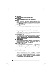
... is [Fast]. The default value is [Disabled]. If you adjusting them. BIOS SETUP UTILITY Main Smart Advanced H/W Monitor Boot Security Exit Hardware Health Event Monitoring CPU Temperature M / B Temperature CPU Fan Speed Chassis Fan Speed Vcore + 3.30V + 5.00V + 12.00V : 37 C / 98 F : 31 C / 87 F : 3400 RPM : N/A : ...Exit v02.54 (C) Copyright 1985-2003, American Megatrends, Inc. You can freely adjust the target fan speed according to the target CPU temperature that you to use only under BIOS setup and Windows / Linux OS. 3.5 Hardware Health Event Monitoring Screen In this option...
... is [Fast]. The default value is [Disabled]. If you adjusting them. BIOS SETUP UTILITY Main Smart Advanced H/W Monitor Boot Security Exit Hardware Health Event Monitoring CPU Temperature M / B Temperature CPU Fan Speed Chassis Fan Speed Vcore + 3.30V + 5.00V + 12.00V : 37 C / 98 F : 31 C / 87 F : 3400 RPM : N/A : ...Exit v02.54 (C) Copyright 1985-2003, American Megatrends, Inc. You can freely adjust the target fan speed according to the target CPU temperature that you to use only under BIOS setup and Windows / Linux OS. 3.5 Hardware Health Event Monitoring Screen In this option...
Quick Installation Guide
Page 2
Red) 29 ATX 12V Connector (ATX12V1) 15 Secondary SATAII Connector (SATAII_2; Red) 2 ASRock G31M-GS / G31M-S Motherboard Orange) 25 PCI Express x16 Slot (PCIE2) 11 Fourth SATAII Connector (SATAII_4; Orange) 26 PCI Express x1 Slot (PCIE1...SATAII Connector (SATAII_1; Motherboard Layout English 1 PS2_USB_PWR1 Jumper 16 USB 2.0 Header (USB6_7, Blue) 2 775-Pin CPU Socket 17 USB 2.0 Header (USB4_5, Blue) 3 North Bridge Controller 18 Chassis Fan Connector (CHA_FAN1) 4 CPU Fan Connector (CPU_FAN1) 19 Floppy Connector (FLOPPY1) 5 2 x 240-pin DDR2 DIMM Slots 20 EUP Audio ...
Red) 29 ATX 12V Connector (ATX12V1) 15 Secondary SATAII Connector (SATAII_2; Red) 2 ASRock G31M-GS / G31M-S Motherboard Orange) 25 PCI Express x16 Slot (PCIE2) 11 Fourth SATAII Connector (SATAII_4; Orange) 26 PCI Express x1 Slot (PCIE1...SATAII Connector (SATAII_1; Motherboard Layout English 1 PS2_USB_PWR1 Jumper 16 USB 2.0 Header (USB6_7, Blue) 2 775-Pin CPU Socket 17 USB 2.0 Header (USB4_5, Blue) 3 North Bridge Controller 18 Chassis Fan Connector (CHA_FAN1) 4 CPU Fan Connector (CPU_FAN1) 19 Floppy Connector (FLOPPY1) 5 2 x 240-pin DDR2 DIMM Slots 20 EUP Audio ...


